HB-9 updated text (PDF) - Corbin Bullet Swaging
HB-9 updated text (PDF) - Corbin Bullet Swaging
HB-9 updated text (PDF) - Corbin Bullet Swaging

You also want an ePaper? Increase the reach of your titles
YUMPU automatically turns print PDFs into web optimized ePapers that Google loves.
<strong>Corbin</strong> Handbook<br />
of<br />
<strong>Bullet</strong> <strong>Swaging</strong><br />
No. 9<br />
Revised September 2012<br />
by<br />
David R. <strong>Corbin</strong><br />
<strong>Corbin</strong> Manufacturing & Supply, Inc.<br />
PO Box 2659<br />
White City, OR 97503 USA<br />
www.<strong>Corbin</strong>s.com<br />
1
<strong>Corbin</strong> Handbook of <strong>Bullet</strong> <strong>Swaging</strong>, No. 9<br />
Revised September 2012<br />
© Copyright 2004, 2012 David R. <strong>Corbin</strong><br />
All rights reserved.<br />
May not be reproduced by any means, including electronic and<br />
mechanical, without the expressed written permission of the copyright<br />
holder.<br />
Published by:<br />
<strong>Corbin</strong> Manufacturing & Supply, Inc.<br />
PO Box 2659<br />
White City, OR 97503 USA<br />
541-826-5211<br />
Mon-Thurs 10am-6pm<br />
Fax: 541-826-8669<br />
24/7<br />
E-mail: Sales@<strong>Corbin</strong>s.com<br />
www.<strong>Corbin</strong>s.com<br />
2
Table of Contents<br />
1. Introduction to <strong>Bullet</strong> <strong>Swaging</strong> ..................................................... 5<br />
2. What is <strong>Bullet</strong> <strong>Swaging</strong>? .............................................................. 10<br />
3. <strong>Bullet</strong> <strong>Swaging</strong> Secrets ................................................................ 25<br />
4. Tubing Jackets ............................................................................. 48<br />
5. Drawn Strip Jackets .................................................................... 67<br />
6. Base-Guard <strong>Bullet</strong>s ...................................................................... 77<br />
7. Draw Dies ..................................................................................... 82<br />
8. Making Lead Cores...................................................................... 97<br />
9. <strong>Swaging</strong> with a Reloading Press ............................................... 106<br />
10. <strong>Bullet</strong> <strong>Swaging</strong> Presses............................................................ 127<br />
11. Lead, Base-Guard, Gas-Checked and<br />
Paper Patched <strong>Bullet</strong>s ............................................................ 156<br />
12. Jacketed Semi-Wadcutters..................................................... 172<br />
13. Full-Jacket, Flat Base <strong>Bullet</strong>s ................................................. 183<br />
14. Lead Tip <strong>Bullet</strong>s ....................................................................... 196<br />
15. Rebated Boattails..................................................................... 205<br />
16. Shotgun Slugs and Airgun Pellets........................................... 212<br />
17. <strong>Bullet</strong>-Makers’ Tools ................................................................ 217<br />
18. Custom Toolng ......................................................................... 228<br />
19. Lubricants and Chemicals ...................................................... 240<br />
20. Books and Software ................................................................ 248<br />
21. Delivery Information .............................................................. 253<br />
22. Warranty ................................................................................... 260<br />
23. Non-Disclosure Agreements .................................................. 263<br />
3
1. Introduction to <strong>Bullet</strong> <strong>Swaging</strong><br />
Good morning! I’m Dave <strong>Corbin</strong>, and for over 40 years I’ve had the<br />
second best job in the world: I help people make the state-of-the art bullets<br />
that you’ve read about in the gun magazines. Nearly every custom<br />
bullet maker started with equipment developed at the <strong>Corbin</strong> die-works.<br />
They have the best job in the world!<br />
All you have to do is scan the pages of nearly any magazine catering<br />
to handloaders, and you’ll see dozens of ads from our clients; the articles<br />
are constantly talking about the bullets our clients make, and the major<br />
ammunition firms are buying the bullets made on <strong>Corbin</strong> equipment for<br />
use in their premium ammo. There has been a lot more research and<br />
development that you don’t read about, because it isn’t intended for the<br />
general shooting public. I can now include a small amount of that information<br />
in this edition.<br />
<strong>Corbin</strong> Manufacturing publishes an e-book called the “World Directory<br />
of Custom <strong>Bullet</strong> Makers” listing hundreds of individuals and firms<br />
whose names you may recognize if you are familiar with handloading.<br />
When I read the list, I remember someone’s enthusiasm for the new business<br />
venture they were able to start, thanks to the power of bullet swaging.<br />
Olympians and world champions in every field of firearms sports,<br />
from benchrest to air gun competition, using everything from paperpatched<br />
blackpowder bullets to custom fin-stabilized shotgun slugs, have<br />
come to the die-works where we have toiled for the last quarter century<br />
and into the first quarter of this one, some just to improve their alreadyoutstanding<br />
achievements, and some to help others become better shooters<br />
by manufacturing new ideas in how a given bullet should look and be<br />
constructed.<br />
Engineers from the Department of the Army, Air Force Armament<br />
Labs, Sandia National Laboratories, DuPont, Northrop, Lockheed, Martin-Marietta<br />
and other defense-related organizations have visited us over<br />
those years, sometimes sketching ideas on napkins during lunch. Tools<br />
and designs we worked on are in use today all over the world, wherever a<br />
long range, high precision projectile or a very special purpose bullet that<br />
could only be made efficiently by the high precision techniques of swaging,<br />
is needed for the job.<br />
Whether it is protecting an important public figure at long range or<br />
picking a pine cone from the top of an experimental tree, whether it is<br />
surveying a dense mountain jungle with remotely launched flare projectiles<br />
designed for vertical firing stability, or stitching mirror-based bullets<br />
5
in an arctic ice sheet from a low-flying aircraft so a laser beam can measure<br />
the depth and estimate the strength of the ice to hold a transport<br />
plane, or whether it is the grim responsibility of instantly stopping a terrorist<br />
before he can take the life of another hostage—regardless of the<br />
purpose, we sat through many meetings pouring over blueprints, computer<br />
readouts, and sketches, helping design projectiles for visitors from<br />
the far corners of the earth.<br />
Yet, this work is only the continuation of development begun by other<br />
pioneers of bullet swaging: people like Ted Smith, who founded the old<br />
SAS Dies in the 1950’s; Harvey Donaldson, who experimented with some<br />
of the first dies to make .224 bullets from fired .22 cases; Walt Astles and<br />
Ray Biehler, who developed the principle of upward expansion and the<br />
two-die swage technique which replaced the RCBS single-die take-apart<br />
system; Charlie Heckman, a pioneer swage maker; and so many others<br />
whose names are probably unknown to modern shooters, but to whom all<br />
shooters owe a debt for their contributions to the perfection of bullets.<br />
You may know that the RCBS company (initials of which mean Rock<br />
Chuck <strong>Bullet</strong> Swage) got started making bullet swaging equipment, but<br />
soon dropped it in favor of more easily produced reloading dies. You may<br />
even have heard Speer <strong>Bullet</strong>s was started by Vernon Speer swaging .224<br />
caliber bullets from fired .22 LR cases.<br />
But bullet swaging played a much larger part than just that, in leading<br />
to the products and companies you use today: Hornady, Sierra, Nosler,<br />
Barnes, Swift and a host of other mass production operations owe their<br />
very existence to the concept of bullet swaging. Today, more than four<br />
hundred custom bullet firms—operated by people who probably differ<br />
from yourself only in having taken the step of putting their intense interest<br />
in firearms to work at a profitable and enjoyable occupation—produce<br />
specialty bullets. We call this field “custom bullet making”, the elite corps<br />
of bullet manufacturing providing initial concept advances sometimes<br />
copied years later by the larger “mass production” bullet makers.<br />
So, what is bullet swaging and how do you do it? What do you need to<br />
get started? How much does it cost? What are the advantages and drawbacks<br />
compared to casting or just buying factory bullets? Can you swage<br />
hard lead, make partitioned bullets, make your own jackets, make plain<br />
lead bullets or paper patched slugs?<br />
I answer those questions a thousand times a week and I never get<br />
tired of it. But to save you a lot of time on the phone, I’ve written most of<br />
those answers here. If you read through this book and think I have left<br />
something out, you are absolutely right: I left out about seven more books<br />
of information! Those are available if you care to read further.<br />
6
<strong>Swaging</strong> is so simple you can do it correctly after just a couple of<br />
tries. Then you’ll see it’s also extremely versatile and powerful: you can<br />
do one more thing, and then one more after that, and soon you will have<br />
the whole top of your loading bench covered with one-of-a-kind bullets,<br />
some of which no one in the world has ever made before. That’s why it<br />
takes at least seven more books to make a dent in the vast array of things<br />
you might do, could do, if you wished. Only your imagination limits the<br />
possibilities.<br />
A deeper study of the specifics of bullet swaging technique and tooling,<br />
including products made by people other than <strong>Corbin</strong>, can be found<br />
in the book “Re-Discover <strong>Swaging</strong>”, so named because swaging was, in<br />
fact, discovered once before and then almost lost: during the period of<br />
1948-1963 there were many die-makers who produced swaging equipment,<br />
but none of them offered a comprehensive enough range of products<br />
to insure their own survival, or that of the swaging arts.<br />
<strong>Corbin</strong> Manufacturing was the first comprehensive effort to preserve<br />
and further the technology with information, supplies and tools from one<br />
source. Whereas other die-makers tended to be secretive and often died<br />
with their secrets of bullet making, <strong>Corbin</strong> began publishing information<br />
that would help advance the field, from our beginning days.<br />
<strong>Bullet</strong> swaging, by the way, is pronounced “SWAY-JING” and rhymes<br />
with “paging”. There is a blacksmith technique for pounding hot metal<br />
around a form that is called “swedging” but it is a different sort of thing<br />
altogether.<br />
If you want to really dig into the subject and learn things most people<br />
never discover, then order the Book Package. You get another copy of this<br />
book free, with it. Give this copy to a friend. Who knows: maybe between<br />
the two of you, a new bullet making business may develop that rivals the<br />
fame of some of our other clients? It could happen: it has happened over<br />
400 times so far!<br />
Warning! While the majority of handloaders say that they enjoy<br />
reading the additional side trips that clutter my books, some have complained<br />
that I don’t get “to the point” and just tell them 1-2-3 how to<br />
make a bullet. I agree that this would be a good idea, if only I had some<br />
way to know exactly which bullet they wanted to make.<br />
You see, every bullet can be described with a step-by-step, cookbook<br />
approach, but there are tens of thousands of different styles and shapes<br />
you can make, and not all of them are made the same way! The same<br />
bullet may be made in slightly different ways with different presses and<br />
the dies which fit them.<br />
7
Instead, I try to teach the principles involved. That way, you know<br />
the terminology and won’t be confused by thinking a die is a punch or a<br />
punch holder is a die. You will understand that every swaging operation<br />
expands the components upward in size, so that you won’t try to put a<br />
larger part into a smaller hole except when drawing down (which you will<br />
know is different from and opposite to swaging).<br />
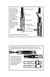
You will know that in a swaging press, the die screws into the ram and<br />
the external punch fits into the press top, in a floating punch holder, whereas<br />
in an ordinary reloading press used for swaging, the die fits the top and<br />
the external punch fits the ram. You will understand that a smooth, stepless<br />
ogive requires a set of dies that includes a point forming die, whereas<br />
a shouldered semi-wadcutter style bullet can be made in a single die.<br />
All these things will be familiar to you before you start. You won’t<br />
need to be told specifically how to make every possible bullet, because<br />
you will understand the basic principles and how to apply them to any<br />
bullet.<br />
When we ship orders for dies, they come with specific, simplified 1-2-<br />
3 instructions that apply to the design you ordered. Sometimes these<br />
instructions are applicable to many calibers in a popular style, so we print<br />
the instructions on a form. Sometimes your bullet design needs specific,<br />
handwritten details and tips we discovered while developing the dies, and<br />
then we write special instructions for you. But in all cases, if you are<br />
prepared with a good background of general swaging principles, you can<br />
avoid damaging the tools and begin making bullets with higher confidence.<br />
<strong>Swaging</strong> versus Casting<br />
Everyone seems to be familiar with bullet casting (melting metal and<br />
pouring the molten liquid into a split mould, letting it cool and shrink,<br />
and then opening the split mould halves so that the frozen bullet metal<br />
can drop out).<br />
Casting involves a lot of time and introduces quite a few potential<br />
sources of inaccuracy, but it works reasonably well within a limited range<br />
of capabilities. You have to have a lead pot and a supply of lead, a mould<br />
and mould handles, then a lubricator and sizer machine to prepare the<br />
bullets. The sizer machine needs sizer dies and base and nose punches to<br />
fit the shape and caliber of bullet. It also require lubricant to apply to the<br />
bullet.<br />
The first thing you have to do with casting is to melt a pot of lead,<br />
flux it and stir it, make sure that the dross and dirt is cleaned from the<br />
lead, ventilate the room and make sure no moisture gets into the pot and<br />
8
lows the hot lead out with a bang. You need to be reasonably careful<br />
about fire and burns, and about potentially toxic fumes (no eating or smoking,<br />
plenty of good ventilation). After about half an hour of this melting<br />
and preparation, you are ready to start casting bullets.<br />
The first few attempts usually make incomplete or frosty bullets, until<br />
the mould is warmed up. During the casting process, the mould contains<br />
liquid metal that is cooled to solidify on every single bullet made, so it is<br />
constantly changing diameter from thermal expansion.<br />
When you open the split halves, part of the mould is exposed to room<br />
temperature air while the rest is protected from it, which cannot fail to<br />
slightly warp the roundness of the mould. The two halves of the mould<br />
cannot be put together with zero tolerance, as they would be far too hard<br />
to swing open and closed again, so there is some degree of “slop” in the fit<br />
of the pivot and the alignment pins. Add up all these factors and you can<br />
see that a cast bullet has a limit of roundness and diameter control based<br />
on physics, rather than skill or quality of manufacture.<br />
In contrast, a swaging die runs at room temperature and does not<br />
contact hot metal. It flows the metal under tons of pressure, squeezing<br />
out all air pockets and voids. The bullet takes its shape and finish from the<br />
diamond-lapped hardened surface of the die. The die is not split, but is a<br />
solid tube or cylinder with thick walls to hold the pressure. The bullet<br />
material goes in one end, and is pushed back out the same way. Two<br />
precisely fitted punches seal both ends of the die. One moves in and out<br />
to load material, and the other acts as an ejector.<br />
The problems associated with heat expansion, swinging split section<br />
alignment, and the time required to prepare are absent or minimized with<br />
swaging. In addition, the die can make a wide range of weights depending<br />
on how much material you put into it. A mould makes approximately<br />
one weight because you must fill it to make a bullet. These are just a few<br />
of the differences between casting and swaging.<br />
There is one thing you can do more quickly and easily with casting<br />
than with swaging: you can form a lead bullet with grooves for lubrication.<br />
With swage dies, the bullet goes in and then comes back out the<br />
same hole in the die. If you think about that for a minute, you will understand<br />
that it would not be possible to swage a groove into the side of the<br />
bullet and then push it back out of the die. The die would have to be<br />
“split” like a mold. While this is possible, it is not cost effective. Fortunately,<br />
you can roll grooves into a swaged lead bullet with a grooving tool<br />
made by <strong>Corbin</strong>, or use better bullet designs or surface lubricants that<br />
eliminate the need for grooves. And you can swage jacketed bullets, so<br />
that separate lubricant is not required.<br />
9
10<br />
2. What is <strong>Bullet</strong> <strong>Swaging</strong>?<br />
Before we talk about swaging a bullet, we need to make sure the concept<br />
of a bullet is clear. When we say “bullet”, we mean the projectile or<br />
part of the cartridge that is propelled through the air. The news media and<br />
popular movies and magazines often refer to a “bullet” as the entire cartridge<br />
with powder, primer, bullet and case. <strong>Bullet</strong> swaging has nothing to<br />
do with the rest of the cartridge, but concentrates on the part that flies to<br />
the target. In some countries, shooters refer to the bullet as the “head” or<br />
the “bullet head” and call the entire cartridge a “bullet”.<br />
There is a good reason not to call the cartridge a bullet, as popular<br />
media seems inclined to do. The bullet is inert metal without any propellant<br />
involved, which means that it should be treated as a precise metal<br />
product, not some dangerous component subject to transportation restrictions<br />
and tariffs. A bullet is as safe as a writing pen, probably safer:<br />
people have been stabbed with uncapped ball-point pens. I accidently<br />
stabbed myself once, stupidly, reaching quickly into a coat pocket.<br />
Finding a “bullet” in the possession of an airline traveller should be no<br />
more cause for alarm than finding a coin. Unfortunately, through ignorance<br />
and imprecise language, the term “bullet” causes problems where it<br />
should not. Some of them are of practical concern to those who show<br />
their products and must carry samples. More than one new bullet maker<br />
has run up against unrealistic insurance, business licensing and zoning<br />
problems because of ignorance about what a “bullet” actually means.<br />
A bullet maker is a precision metal product manufacturer, who could<br />
just as well be making precision bearings or electronic fittings. But try to<br />
explain that to a bureaucrat who just found out you intend to make bullets<br />
in the home enterprise, or the hysterical airline security guard who<br />
scanned a couple of samples in your pocket, or the customs agent whose<br />
eyes widen as he reads your declaration of “bullet-making” equipment<br />
being taken into the country! Such a pity these things happen. The wise<br />
bullet-maker soon learns to discuss precision formed parts rather than<br />
bullets, around those who know nothing about the field.<br />
<strong>Corbin</strong> equipment can swage bullets from .123 diameter up to about<br />
1-inch diameter (.998-inch is the 4-bore blackpowder elephant cartridge,<br />
for example). The “bullet” can be an airgun pellet, a swaged round ball, a<br />
shotgun slug, a fragmenting shot or powdered metal filled jacketed pistol<br />
bullet, a partitioned or multi-jacketed projectile, and it can be made of<br />
pure lead, various lead alloys, powdered metals pressed together with or<br />
without a jacket, conventional jacketed bullets with a lead core with or<br />
without other inserts such as penetrators or light plastic fillers to shift the
center of gravity and create fast, light but long projectiles. In short, just<br />
about anything that can be launched from a small arm, be it airgun, shotgun,<br />
rifle or pistol, and some kinds of machine guns and cannons, can be<br />
swaged and is considered a bullet.<br />
<strong>Bullet</strong> swaging (SWAY-jing, sounds like “paging”) is the process of applying<br />
extremely high pressures (from 15,000 PSI for soft, unjacketed<br />
bullets to as high as 150,000 PSI for solid copper bullets) to materials<br />
contained in a very tough, extremely well finished die, so that the material<br />
will flow at room temperature and take on the shape of the die and the<br />
ends of the punches.<br />
A die is a vessel to hold the pressure. A punch is a rod that fits into the<br />
hole in the die and seals off the end. If you refer to a punch as a die and<br />
vice versa, you may cause some interesting errors when placing orders.<br />
One of the first things to learn is the right names for the basic parts involved<br />
in the swaging process. You wouldn’t call a pistol a shotgun, would<br />
you? Probably not, or else you might get some odd-looking mail-order<br />
holsters!<br />
A business that is good at making swage dies probably will be buried<br />
in orders, with long waiting lists. Waiting up to a year to get your “die”<br />
and finding out everyone thought you wanted the “punch” that you asked<br />
for may be frustrating. Use the right terms and avoid this problem.<br />
In swaging bullets, you will always be putting a smaller diameter object<br />
(lead, jacket, or a combination of both) into a slightly larger die cavity<br />
or hole. Each step in swaging increases the diameter of the components,<br />
until they reach the final diameter in the last die. <strong>Swaging</strong> never<br />
reduces the diameter. You will only have stuck bullets and hard ejection if<br />
you try to push a slightly larger part into a slightly smaller hole. This is<br />
the difference between swaging and drawing. You never swage anything<br />
“down”. You never draw anything “up”.<br />
In drawing, you do push a larger part through a smaller hole, to reduce<br />
the diameter. This kind of die is a ring, not a cylinder closed on one<br />
end. The jacket or bullet that you are reducing is pushed through the ring,<br />
and is decreased in diameter when it comes through the other side.<br />
We use drawing to make longer, smaller caliber jackets from shorter,<br />
larger diameter ones. Also, within some narrow limits, it is possible to<br />
make a smaller caliber bullet from a larger one, although this degrades the<br />
quality of the bullet unless special conditions are observed. Usually the<br />
difference in diameters has to be within 0.006 thousandths of an inch<br />
when you reduce finished bullets by drawing. Jackets can be drawn much<br />
more than this, usually up to 30% smaller in one draw.<br />
11
A jacket is the “skin” of a bullet, usually made of copper or a copper<br />
alloy with zinc (most commonly 5% to 10% zinc). Jackets can be used, or<br />
not, depending on the bullet design. A jacket isolates the lead core from<br />
contact with the barrel, and allows the bullet to be shot much faster without<br />
friction melting the core and smearing it in the barrel, which is called<br />
“lead fouling”. Enough of that spoils the accuracy and is hard to remove.<br />
We’ll discuss jackets in detail later.<br />
<strong>Bullet</strong> jackets properly designed for home swaging are always made<br />
smaller than the finished caliber, then expanded by putting lead inside<br />
them and compressing it with a punch. The lead flows to fill the jacket,<br />
then pushes the jacket out a few thousandths of an inch to meet the die<br />
wall, which stops the expansion. One end of the die is sealed with a punch,<br />
which stops the end from popping off the jacket. If you try to use a jacket<br />
larger than the die hole, it can’t spring back slightly when you release the<br />
pressure. In fact, if you push a jacket into a die that is too small for it, the<br />
jacket will be trying to spring back to original size, and thus pressing<br />
itself firmly against the die walls. This causes difficult ejection and is hard<br />
on the equipment.<br />
The right way to swage bullets is to use jackets that fit easily into the<br />
die by hand, and lead cores which are small enough to easily drop into the<br />
jacket. Jackets of course have some wall thickness, generally from 0.015<br />
to 0.035 inches (although there is no rule that says you can’t make much<br />
thicker jacket walls if you want them). To determine the diameter of lead<br />
core which fits inside, you must subtract two times the wall thickness<br />
from the caliber, and then subtract an additional five to ten thousandths<br />
of an inch to allow for easy insertion, tolerances in the lead wire diameter,<br />
and the fact that you may have two or three steps with a small amount of<br />
expansion in each, to get to final caliber.<br />
Basic swage dies<br />
There are two basic designs of swaging dies made by <strong>Corbin</strong>. All the<br />
specific styles of dies are patterned after one or the other of these basic<br />
designs. One design is a cylinder with a straight hole through it. The other<br />
is a cylinder with a semi-blind hole, having the shape of the bullet except<br />
that at the tip, there is a tiny hole (.052 to .120 inches is a typical range)<br />
fitted with a strong piece of tempered spring wire.<br />
The first design can be used for any sort of operation where two punches<br />
can form the desired shape on the end of the enclosed materials. An example<br />
would be a “Core Swage” or “CSW-” die, which takes in a piece of<br />
cut lead wire or cast lead pellet (the “core” of a bullet) and gives it a<br />
precise diameter with smooth flat ends and extrudes off whatever sur-<br />
12
plus lead there might be for the weight you desire. Three little bleed holes<br />
in the sides of the die, at 120 degree intervals, allow surplus lead to spurt<br />
out as tiny wires which are sheared off during ejection. Core swages are<br />
used to make the lead filling (core) a precise weight after it has been cast<br />
from scrap lead, or cut from a piece of lead wire.<br />
This kind of die can also be equipped with a punch having the shape<br />
you want for the bullet base, and another punch, at the opposite end,<br />
having the shape you want for the nose. Both shapes will be in reverse:<br />
the bullet nose is formed in a cavity in the punch, and a hollow base bullet<br />
would use a convex or projecting punch. This is what we call a “Lead<br />
Semi-Wadcutter” or “LSWC-” type of die. That doesn’t mean you have to<br />
make a particular shape that you know as a semi-wadcutter bullet; it’s just<br />
a short-hand way of saying you could do that, or make any other shape<br />
that has the entire nose right out to the full bullet diameter formed by<br />
pushing the lead into a cavity in the end of the nose forming punch.<br />
With most swaging dies, one punch always stays partly inside the die.<br />
It slides back until a ledge within the swaging press ram stops it. To eject<br />
the bullet out of the die, this punch is pushed forward toward the die<br />
mouth. It can be pushed by a pin or knockout bar incorporated in the<br />
design of the press (with a <strong>Corbin</strong> swage press), or it can be pushed by a<br />
plunger (with a standard reloading press). We call this punch the “Internal<br />
Punch” because it always stays in the die. It is “internal” or inside, and<br />
never comes out during normal operation. It merely slides up and down,<br />
a distance slightly less than the die length, and stops within the die so as<br />
to close one end for swaging. It has to move from this position to the die<br />
mouth, in order to push out the finished bullet.<br />
The other end of the die accepts the material to be swaged. Obviously,<br />
that end has to be fitted with a punch that comes out all the way, or<br />
there would be no way to put the material inside. The punch which comes<br />
out, so you can insert material into the die, is the “External Punch”. It is<br />
external to the die during the time you are placing the components in the<br />
die, and when you move the ram back to eject the bullet. The “Ram” is<br />
the moving tubular steel part of the swaging press that holds the die and<br />
the internal punch (in any <strong>Corbin</strong> press).<br />
With <strong>Corbin</strong> swaging presses, the external punch fits into an adjustable<br />
“Floating Punch Holder” in the press head or top plate. This assembly<br />
is often mistaken for the swage die, because in reloading, a similarappearing<br />
reloading die fits the head of your reloading press. <strong>Swaging</strong> is<br />
“upside-down” from reloading, for reasons that will be clear by the time<br />
you finish this book.<br />
13
Again, the steel rods that push the material into the die, and seal the<br />
die against all that pressure during swaging, are called “punches”. The<br />
round cylinder with the hole in it is called the “die”. If you fit punches to<br />
a particular die, you have just made a “die set”, because it is a set of<br />
matching parts that work together. You can have several dies and punches<br />
in a given set, because all the various dies in that set are designed to work<br />
in succession, one after another, to yield a final bullet shape, weight, and<br />
construction.<br />
The only difference between a “Core Swage” die, which we call a<br />
“CSW” die in the language of swaging, and a “LSWC” die, is the use of<br />
punches which have the final bullet base and nose shape machined on<br />
their ends, and of course the diameter of the die is made to form the final<br />
bullet diameter in the LSWC die. Usually the LSWC type of die makes<br />
either lead bullets, gas checked, or “Base-Guard” bullets (a superior kind<br />
of gas check that scrapes fouling out of your barrel with every shot fired).<br />
It isn’t used for bullets that have the jacket covering up the bleed holes in<br />
the die wall, which includes most jacketed rifle bullet designs.<br />
The core swage die generally has flat punch ends and a diameter far<br />
less than the final caliber. It is used to prepare the lead core to fit inside a<br />
bullet jacket, in most cases (although you don’t have to use a jacket—<br />
you can just swage the lead core to final shape in the next die if you<br />
desire to make a high quality lead bullet, such as a paper-patched or Gase-<br />
Guard style). Lead bullets can be made either in one die (the LSWC) or in<br />
two dies (the CSW and CS types, or the CSW and PF types). Jacketed<br />
bullets generally require at least two and sometimes three or more dies.<br />
When we make the die, we need to know what it will be used for. If<br />
you say you want a .308 core swage die, you probably do not want the<br />
hole to be .308 inches because a core swage has to make a core that fits<br />
inside a jacket, and the jacket will usually be about .3065 inches on the<br />
outside before swaging. The wall thickness of the jacket might be .028<br />
inches at the base, so the core would have to be no larger than .3065<br />
minus twice .028 (twice the wall thickness), or .2515 inches. So, we need<br />
to have a sample jacket or at least know what jacket you intend to use, or<br />
at the very least to know the diameter you really want for the lead core. If<br />
you supply a jacket, or specify one of ours, then we can determine the<br />
best core diameter to fit into it.<br />
You can cast scrap lead in a core mould, or cut pieces from a spool of<br />
.247 inch diameter lead wire to easily drop into this .2515 bore die, swage<br />
them up to .2515 inch diameter, and then they’d fit nicely into the bullet<br />
jacket. Actually we use .250 inches for the core size to allow for an easier<br />
fit and avoid any trapped air in the jacket bottom.<br />
14
There are two more steps to expand the core inside the jacket, blowing<br />
the jacket out like the skin of a balloon, and then form the ogive on<br />
the bullet to finish it. That is for flat base open tip bullets.<br />
But if you wanted to make a lead .308 diameter bullet for a .30 Mauser<br />
pistol, then we’d make almost the same kind of die but we’d make it with<br />
a bore of .308 inches, and fit it with the right kind of nose and base punches.<br />
So you see that even if the dies look similar and work in a similar way,<br />
their purpose really makes them different dies. That’s why we need two<br />
different names for them. It helps avoid a lot of unnecessary explanation<br />
and errors.<br />
Perhaps you might order a .308 LSWC die, maybe with an “Autoloader”<br />
nose and a “Cup Base”. We would use the short-hand “AL” for<br />
Auto-loader, a sort of rounded semi-wadcutter shape, and “CB” for Cup<br />
Base, which is a shallow concave base form. To us, the term “semiwadcutter”<br />
is a general description for a bullet style that can be made<br />
using a punch to form the nose, instead of a point forming die. The Target<br />
Wadcutter, Button-Nose Wadcutter, Keith, Auto-Loader, and even round<br />
nose SWC styles are all subsets of the semi-wadcutter group, since every<br />
one of these styles is made in the same die just by changing the nose<br />
punch.<br />
Two other kinds of dies that are made with a straight hole and two<br />
full-diameter punches are the “Lead Tip” die and the “Core Seat” die.<br />
These don’t have any bleed holes around their middle. The core seat die<br />
is also called a “Core Seater” and abbreviated “CS”. The lead tip die is also<br />
called a “Lead Tip Former” and is abbreviated “LT”. It is not the same<br />
thing as a point former or “PF” die.<br />
The purpose of a core seat die is to expand the jacket, which is made<br />
slightly less than final diameter, and at the same time achieve a very tight<br />
fit between the core and jacket. You can use either a punch that fits into<br />
the jacket, to make open tip style bullets, or you can use a punch that fits<br />
the die bore, and thus make large lead tips. The use of a CS die to make<br />
lead bullets (after first swaging the lead core to exact weight in the CSW<br />
die) is a perfectionist’s way to build lead wadcutter or semi-wadcutter<br />
bullets: it can be more precise because you separate the pressure needed<br />
to extrude surplus lead from the pressure required to form the edges of<br />
the bullet nose and base.<br />
In a LSWC die, the pressure stops building when the lead begins to<br />
extrude through the bleed holes. Thus, some shapes of bullets with deep<br />
nose cavities or hollow bases and sharp edges may not receive enough<br />
pressure to fully take on the exact punch shape, if that pressure is higher<br />
than the pressure which causes lead to spurt out the bleed holes. By first<br />
15
using a CSW die to adjust the weight, and then using a separate CS die to<br />
form the nose and base, the pressure issue is resolved for all shapes and<br />
styles.<br />
A punch with a cavity in the end makes the bullet with a semi-wadcutter<br />
shoulder (the edge of the punch must be in the neighborhood of<br />
.02 inches thick in order to stand the high swaging pressures). A core<br />
seating punch with a projection on the end, usually conical, makes a hollow<br />
point cavity in the lead core. Of course, you can use flat, domed,<br />
slightly convex, or highly pointed punch shapes to suit your desires, and<br />
make virtually any kind of base you want just by changing the punch.<br />
Often this will be the internal punch, but you can have the die built with<br />
the base punch being external if you wish. The reason we normally make<br />
the nose punch external to the die is because usually people change the<br />
nose shape much more often than the base, and it is easier to change the<br />
external punch in seconds without removing the die from the press ram.<br />
Technically it would not matter which punch made the nose and which<br />
made the base.<br />
The purpose of the lead tip forming die is to finish the very end of a<br />
pointed (spitzer) bullet, and it isn’t normally used for semi-wadcutter or<br />
large lead tip bullets. It looks just like a core seater, but the bore diameter<br />
is slightly larger than the final bullet size, whereas the core seater diameter<br />
is just slightly smaller than final bullet size. The internal punch of a<br />
lead tip die is designed with a cavity to reshape the extruded lead tip of a<br />
sharp-pointed rifle bullet so that it looks perfect. It cannot form the entire<br />
ogive because the edge of the punch, which must withstand tons of<br />
swaging pressure, cannot be paper-thin and survive.<br />
We started this section talking about two general die designs, one<br />
with a straight hole through it, and one with a semi-blind hole. This second<br />
kind of die came about because, try as you will, there isn’t a reliable<br />
way to make a straight-hole die form a smooth curve from shank to tip.<br />
(The bullet nose curve is called the “ogive”, pronounced OH-jive, and<br />
comes from the French ogee which is the bullet shaped curve over a doorway).<br />
That punch with the cavity machined in the end must have some<br />
thickness at the edge, and this edge will impress itself on the bullet to<br />
make a shoulder.<br />
There’s even more to it than that: if you try to push a jacket into the<br />
cavity in the punch, the edge of the jacket will strike the edge of the<br />
punch. It won’t reliably jump over that edge, but instead either the jacket<br />
or the punch will be crumpled up. In <strong>Corbin</strong> dies, the jacket is far weaker<br />
than the punch, so it folds up. So, that leaves the problem of how to make<br />
16
a typical rifle-style bullet, or a smooth rounded or angled bullet nose of<br />
any type, not having a lead tip from where the jacket stops to the end of<br />
the bullet.<br />
The semi-blind hole die is used whenever the nose or base of the<br />
bullet has to turn inward, away from full bore diameter, without a shoulder<br />
or step. Conventional rifle bullets, boattail bullets, and modern jacketed<br />
handgun bullets with the jacket curving or angling smoothly inward<br />
from the shank to the ogive all require the use of this die design.<br />
By “semi-blind hole”, I mean that the hole in the die is not straight<br />
through the die, but is shaped like the bullet itself. At the tip is a very<br />
small punch to push the bullet out by its nose, and this punch is retracted<br />
a short way up into its little access hole so there is no possibility of the<br />
bullet material pressing against it (which might otherwise bend the small<br />
diameter punch under those tons of pressure).<br />
The “Point Forming” die, which we abbreviate “PF”, accepts either a<br />
lead core, or the seated lead core and jacket combination swaged in the<br />
core seat die. A full-diameter external punch shoves the material into the<br />
point forming die. The material is compressed inward in the small end of<br />
the die, giving the bullet its smooth curve or angled nose (the ogive). The<br />
pressure also expands the shank slightly to final diameter.<br />
The bullet material follows the die wall, right up to the ejection pin<br />
hole and into it, if you push too far. This would put a little parallel “pipe”<br />
on the tip of the bullet, which means you need to back off the depth<br />
adjustment (the punch holder) just a little. The smallest tip which you<br />
can put on the bullet using the PF die is the diameter of the ejection pin.<br />
The smallest ejection pin that can be used is one that will withstand the<br />
ejection pressure without bending. If you happen to forget to apply swaging<br />
lubricant, or if the jacket is larger than the die cavity diameter, the pressure<br />
required to eject the bullet can go considerably higher than the design<br />
parameters. This means that the ejection pin needs a little extra diameter<br />
as a safety margin.<br />
A typical ejection pin (the internal punch for a point forming die is<br />
usually called an ejection pin) for .224 or .243 caliber might be in the .062<br />
to .081 inch diameter range, depending on the expected ejection pressures<br />
and the abuse expected for the die. Dies made for professional bullet<br />
makers, who know how to stop short of bending the punch if anything<br />
goes wrong and who won’t be upset if they do need to replace the ejection<br />
pin now and then, might tend to be closer to .062 inch; dies made for<br />
experimenters who will be exceeding the design limits frequently tend to<br />
have larger ejection pins, as do dies made especially for lead tip bullets.<br />
17
If you make a round nose bullet, a truncated conical pistol bullet, or<br />
even a flat tip rifle bullet in the PF die, it works very nicely for either open<br />
tip or lead tip, depending on how much lead you put into the jacket. If<br />
you make a bullet with the jacket curved around to the diameter of the<br />
ejection pin, then the pin will press down against the end of the jacket and<br />
push the bullet out of a well-finished, diamond-lapped swage die with<br />
relatively low force. But if you want a small, sharp or rounded lead tip,<br />
the ejection pin spoils your plan by making its own flat circle on the very<br />
tip of the bullet.<br />
To form a small lead tip on the bullet, you would need to leave a little<br />
extra lead projecting from the end, which the ejection pin will deform<br />
somewhat during ejection, and then use a “lead tip forming” die, or “LT”<br />
die, to shape up any extra lead. The lead tip die accepts the nearly-completed<br />
bullet from a point form die, so it has a bore diameter slightly<br />
larger than the finished bullet size. This works only because the pressure<br />
needed to shape the lead tip is so low that the bullet shank will not expand.<br />
In fact, since the lead tip die is just minutely larger than the point<br />
forming die, perhaps only .0005 inches, it can assure that the bullets will<br />
be more parallel and have almost no “pressure ring” at the base.<br />
The internal punch of the lead tip die has a cavity that is shaped not<br />
exactly to the same outline as the bullet ogive, but with a slightly shorter<br />
radius. For instance, if the bullet had an 8-S ogive (we’ll explain this in<br />
detail later, but the ogive radius is the length of the radius used to swing<br />
the arc that gives the bullet ogive its shape), the radius of the cavity<br />
shape inside the lead tip forming punch would be perhaps 7-S. That is a<br />
shorter radius.<br />
The result is that the lead tip is formed and the surplus lead pushed<br />
down at a slight shear angle between the wall of the punch and the ogive<br />
of the bullet. If you leave the right amount of exposed lead, the punch<br />
will form a neat lead tip with a very slightly different ogive curve from<br />
the rest of the bullet. If the punch shape were made precisely the same as<br />
the point forming die, the edge of the punch would strike the ogive of the<br />
bullet and create a ring, instead of neatly reshaping the tip.<br />
Bear in mind that the LT die is not used by itself, nor is it used instead<br />
of a PF die. If you use one at all, it would be to follow a point forming die.<br />
Remember, the jacket edge won’t jump over the punch edge. If you already<br />
have a curved jacket, from the PF die, then the edge will slip past<br />
the cavity and let you shape the lead tip.<br />
A LT die can also be used, in some cases, to help close the open tip of<br />
a jacketed bullet more tightly than could be done in the PF die alone.<br />
With care, a bullet maker can learn to push the open end of the jacket<br />
18
nearly closed, by gently using trial and error adjustment of the punch<br />
holder. Not every ogive shape or design lends itself well to this operation,<br />
but enough of them do so that it is worth mentioning.<br />
Rebated Boattails<br />
What about bevel bases or boattail bullets? Those also have the bullet<br />
smoothly angled away from full shank diameter. So, they also require a<br />
variety of the point forming die which is used to shape the base instead of<br />
the nose. The boattail bullet has largely been replaced in swaging circles<br />
by the superior “rebated” boattail, abbreviated “RBT” as opposed to the<br />
more conventional “BT” for boattail.<br />
Why are most custom bullet makers using the RBT instead of the<br />
standard boattail base? There are three reasons:<br />
1) A regular boattail bullet tends to act like the focusing nozzle of a<br />
water hose during the moment it emerges from the barrel. Hot powder<br />
gas rushes around that boattail angle, flow up the sides of the bullet, and<br />
continue in a smooth, laminar low pattern right around the front, where<br />
they break up into turbulent flow and make a fireball of gas—right in the<br />
path of the bullet! You can get up to 15% increased dispersion at the<br />
target just from the buffeting the bullet gets by shooting through this ball<br />
of gas. A flat base bullet deflects most of the gas in a circle of fire, expanding<br />
rapidly out from the bore with a clear space directly in front of<br />
the bullet. The edge of the flat base acts like a “spoiler” to break up the<br />
laminar flow before it can get started. And so does the sharp shoulder on<br />
a rebated boattail! How does a 15% improvement in accuracy sound as a<br />
benefit of using the RBT design?<br />
2) The boattail bullet tends toward more bore erosion than the rebated<br />
boattail, because gas pressure on the boattail tends to peel it back<br />
away from the bore and let some gas up past the bottoms of the rifling<br />
grooves, where it cuts the bullet and the barrel like a hot cutting torch.<br />
The rebated boattail has a 90 degree shoulder that takes the pressure parallel<br />
to the bore, instead of at a compression angle away from it. How<br />
does increased barrel life strike you as a second reason for using RBT<br />
bullets instead of the regular BT style?<br />
3) The tooling lasts longer, costs less to build, and is more easily built<br />
to high standards of precision. <strong>Corbin</strong> Manufacturing has perfected a<br />
method of using two dies, which we call the “Boattail 1” and the “Boattail<br />
2” dies, as a set, to produce a virtually flawless and highly repeatable<br />
19
ebated boattail. Instead of making the boattail angle so it can be higher<br />
on one side or at a little slope like some of the factory production you see<br />
today, this system guarantees that the boattail will start precisely at the<br />
same point on one side of the bullet as it does on the other, every time.<br />
With all these benefits, there is hardly any reason to make standard<br />
boattail dies these days. The RBT has been proving itself all over the<br />
world for more than 30 years to those who are wise enough to give it<br />
attention. However, if you were to ask what base design I would generally<br />
recommend for jacketed bullets up to 250 yard range, I would be unhesitating<br />
in saying a flat base. Rebated or not, a boattail does not give you<br />
superior accuracy in and of itself. It gives you less base drag. Whether or<br />
not that translates into better accuracy than a flat base hinges on whether<br />
the increased drop or higher trajectory arc gives you any problem hitting<br />
your target, and whether there is much cross wind to push the bullet off<br />
course.<br />
Usually at subsonic velocities, the rebated boattail gives you a much<br />
greater benefit in comparison to other drag factors, than it does at Mach I<br />
and above. The shock wave causes far more percentage of total drag at<br />
supersonic velocities, so making the nose more pointed produces more<br />
effect than streamlining the base. The best silenced, subsonic bullets for<br />
special ops have been rebated boattails with a blunt round nose (and other<br />
special features for expansion).<br />
Bevel Bases<br />
Bevel base bullets are made by seating the core in a special “point<br />
forming” die instead of the usual core seating die. The jacket is put into<br />
the die, and the lead is pushed into the jacket. The base of the bullet flows<br />
down into the short, beveled section of the die (it can’t be a punch cavity,<br />
remember, because the edge of the punch would cut the bottom of the<br />
jacket). You could also seat the bullet in a normal core seating die, and<br />
then reform the base in this die, but it would be redundant.<br />
A lead bevel base bullet could be made in two steps: swage the lead<br />
core using a rather large, almost finished diameter core swage, and then<br />
push the bullet into the special point forming die backward, using a nose<br />
punch as the external punch. Come to think of it, any lead bullet with a<br />
smooth ogive (no semi-wadcutter shoulder) can best be made by using<br />
first a CSW die to adjust the weight, and then a PF die to form the ogive.<br />
Without a jacket, you don’t need the CS die, the purpose of which is to<br />
expand the core into the jacket and form a tight, parallel shank.<br />
20
Dies Classified by Press Type<br />
We’ve talked about the basic design of bullet swage dies, in regard to<br />
their function. There is another category for classification of swage dies,<br />
and that is by the kind of press used to operate them. <strong>Swaging</strong> dies can be<br />
designed to operate in a reloading press (with severe limitations on pressure<br />
and precision), or in a number of different models of bullet swaging<br />
presses, both hand and hydraulic-electric powered.<br />
Years ago, we worked out a system of making standard parts for dies<br />
that would cover a wide range of calibers, and thus cut the cost of swaging<br />
through efficient use of what I call “semi-custom production”. We designed<br />
presses and die sets so that we could build similar punch and die<br />
blanks for certain ranges of calibers and bullet lengths, and then choose<br />
among perhaps three die body lengths for every caliber from .12 to .458<br />
in the hand presses, or from .224 to .998-in the dies for our big hydraulic<br />
presses.<br />
We didn’t have to design and build each die from scratch, because we<br />
built a standardized system for determining the minimum requirements<br />
of strength, die length, stroke length, punch geometry and strength, steels<br />
and heat treatment. We could run hundreds of blanks for each of the<br />
various presses, then hand-finish the cavities and hone the rough-finished<br />
punch blanks to a perfect fit during the custom phase of each order. It<br />
combined the economy of mass production with the flexibility and precision<br />
of custom tooling.<br />
<strong>Corbin</strong> swaging dies are up to ten times less costly than competitive<br />
dies without any sacrifice in precision because of this semi-custom production<br />
technique, and the fact that we design and build several different<br />
presses to take full advantage of the kind of operations you might want to<br />
undertake.<br />
The classification by press type also defines the die thread and diameter.<br />
The last letter in the catalog number identifies this classification.<br />
Dies with a catalog number ending in -R (such as the PRO-1-R) fit a<br />
standard 7/8-14 thread reloading press with an RCBS-type button shell<br />
holder ram. The die screws into the press head like a reloading die. The<br />
external punch slips into the T-slot of the ram. You do not also use a shell<br />
holder, since the punch base is made to simulate one.<br />
Dies with a catalog number ending in -M fit either the discontinued<br />
Silver Press, or the current S-Press. They are being phased out of stocking<br />
status in favor of the -S dies, which are larger and stronger, and fit the<br />
current S-Press or its predecessor, the Series II press (discontinued). However,<br />
we will continue to make them on special order, just not as a stock<br />
item. The -M dies have a 3/4-inch diameter main body, a thrust-adsorbing<br />
21
shoulder, and a 5/8-24 threaded tenon. The die screws directly into the<br />
press ram, and the external punch is held in a <strong>Corbin</strong> floating punch holder<br />
in the press head. An example of an -M type die is the LSWC-1-M, a lead<br />
semi-wadcutter die.<br />
The current type -S dies fit the discontinued Series II press or its replacement,<br />
the S-Press (Catalog number CSP-1). An example of a set of<br />
-S dies is the FJFB-3-S, a three-die set. The -S dies have a longer and<br />
larger diameter body than the -M type, being 1-inch diameter. By using<br />
the same 5/8-24 threaded tenon, the thrust shoulder is wider and thus<br />
spreads the force over a wider area (the top of the industrial chromed<br />
alloy steel ram in <strong>Corbin</strong> presses). This also means the S-Press can accept<br />
both the older -M dies and the current -S dies. A bench-type hydraulic<br />
powered version of the S-Press, called the “Hydro-Mite”, also uses these -<br />
S dies.<br />
Finally, the type -H dies are made to fit the <strong>Corbin</strong> Hydro-Press, or<br />
the Mega-Mite hand press. These dies are typically made in a 1.50 inch<br />
diameter, with a length appropriate to the maximum bullet weight to be<br />
produced (up to three inches). The thread tenon is made with a 1-inch 12<br />
thread (meaning 12 turns per inch) to screw directly into the press ram.<br />
The external punch fits into the huge FPH-1-H floating punch holder, in<br />
the press head. A “positive stop” FPH-2-H punch holder is also available<br />
for extreme high precision weight control.<br />
Dies for Other Presses<br />
Special diameters of dies can be built to order, either to fit <strong>Corbin</strong><br />
presses or other presses. Diameters of up to four inches with nearly any<br />
desired thread can be made. Usually it is best to use a standard die that<br />
fits one of the <strong>Corbin</strong> presses, rather than to spend very much on custom<br />
work to fit some other press. In the first place, the cost of special replacements<br />
and additions can quickly use up any savings in using an existing<br />
press versus buying a standard swaging press.<br />
Often I have heard “I already have a press that I want to use” and the<br />
meaning is, “I don’t want to spend money for another press.” I agree, and<br />
would do the same, but only if the cost of building the custom dies and<br />
punches and making them work in this nonstandard press (for swaging<br />
purposes) is still less than just buying a regular swaging press. Often it<br />
costs more to fiddle around with special jobs than it does just to buy a<br />
standard swaging press. And then, from that point on, you don’t have to<br />
worry about any special replacement parts, or additions that also have to<br />
be custom made (meaning both fairly long production delays and additional<br />
cost).<br />
22
Usually, the design of a swaging press gives you a big advantage in<br />
speed, accuracy, and safety over using other kinds of presses. After all, a<br />
pants press, a wine press, a full court press, and a printing press all are<br />
variations on the term “press”, and they are not suitable for reloading.<br />
Having said this, it is still possible to have custom dies built for just about<br />
any press you own. Just bear in mind that there is time involved in making<br />
working drawings, checking the stroke and ejection position, getting<br />
special thread taps and dies (sometimes), setting up the tooling for a onetime<br />
job, and other costs that have long been amortized over thousands<br />
of dies when you choose a standard production design instead.<br />
Besides, we may have spent a couple of decades and tens of thousands<br />
of dollars in testing and improving our standard tools and presses.<br />
Building something for the first time in a different design often requires<br />
some investment in development, which may be a waste of your money<br />
if we’ve already done it a thousand times before in a different and better<br />
system, which would be yours if you just got the right platform to run it<br />
(the proper press). With a different, special tool, you get to pay for any<br />
unforseen development requirements. With our own products, we already<br />
paid for development and you get to benefit from that. It’s usually a better<br />
deal.<br />
<strong>Swaging</strong> Principles<br />
1. Always swage “up”, never “down”. <strong>Swaging</strong> down is a contradiction.<br />
You “draw” down, by pushing something through an open ended<br />
ring die, like our JRD-1 jacket drawing die, or BRD-1 bullet reducing die.<br />
Drawing makes the part smaller in diameter and longer. It can also cause<br />
separation of the core and jacket if done to excess. <strong>Swaging</strong> makes the<br />
part shorter and larger, and tightens the grip of the jacket on the core.<br />
2. Pay attention to the instructions. If there are special written notes<br />
with your die, they are important because they modify or improve the<br />
general instructions and replace them. If there is a difference between<br />
specific notes sent with your set of dies, and anything published in general<br />
(as in this book or in general printed literature), follow the special<br />
written instructions in any respect where they may differ. <strong>Swaging</strong> is partly<br />
an art, and various materials or sizes may react differently to the same<br />
general kind of operations.<br />
3. Use the right terminology! I cannot stress enough how important it<br />
can be to read what you have before you start to use it, and order the right<br />
part numbers and names of parts. People call the external punch everything<br />
from a “pin” to a “ram” to a “die” to a “die punch”. How are we<br />
supposed to know what you mean? If you order it wrong, you get to pay<br />
23
a restocking fee or, if it is custom made for you, then it may not be returnable.<br />
A die is the vessel or cylinder that holds the material. A punch fits<br />
into the end of the die and pushes on the material. A “pin” is part of the<br />
pivot system of the press, or the wire ejection pin that fits into a point<br />
forming punch. A “ram” is the moving steel drive component of your<br />
press into which the swage die screws. There is no such thing as a “diepunch”<br />
or a “punch-die”: putting terms together to suit yourself just confuses<br />
everyone.<br />
4. Use the right materials! A set of dies made for a specific jacket, a<br />
certain lead hardness, or a certain alloy and size of copper tubing, may be<br />
able to work with other materials but probably not without adjustments<br />
to the punch and/or die dimensions and possibly not without developing<br />
differences in technique. Nearly all problems with broken dies and stuck<br />
parts or improper sizes comes from the use of materials other than those<br />
we used to develop the tools. Hardness, grain and dimensions make a<br />
huge difference in your success.<br />
24
3. <strong>Bullet</strong> <strong>Swaging</strong> Secrets<br />
Before I start telling you about the various kinds of swaging presses<br />
and dies that work with them, and why you might want to select a given<br />
type of press and die for a certain kind of bullet making, it would be useful<br />
for you to know some facts that have taken decades to figure out, and<br />
which most of the people who have figured them out wish to keep from<br />
you, since it might affect their own income if you knew.<br />
If you don’t care to wade around in the backwaters of history, skip<br />
this chapter and go on to the “How To” chapters that follow. It isn’t absolutely<br />
necessary to be aware of all the misconceptions, phony physics,<br />
and junk science that is tossed about as if it were gospel. A lot of people<br />
make a good living based on these misconceptions, whether on purpose<br />
or because they believe it too, and it is not helping them a bit if you<br />
become aware of the errors in thinking that make this possible. But I<br />
suppose someone has to support those people: you can, if you wish!<br />
The Myth of Exclusion<br />
The most common misconception about bullet swaging is that only a<br />
few people really have the money and expertise to do it right—that equipment<br />
to make a good bullet is far too costly for you to buy, and the techniques<br />
are filled with “secrets” that only a few bullet-makers are smart<br />
enough to understand. In other words, stay away from swaging because<br />
(1) you are not smart enough and (2) you cannot afford the right equipment.<br />
Leave it to the “experts” who know best, in other words... the same<br />
“experts” who are eager to tell you this, and to scoff when you mention<br />
that you might have found a way to try it yourself.<br />
The reason this myth is repeated in print every year is simple. Think<br />
about it: if you were making a reasonably good income from selling your<br />
own custom swaged bullets and someone asked you to tell a magazine<br />
audience all about your business, would you tell them “It’s easy: anybody<br />
can do it with a little reading and a few hours of experimenting with<br />
moderately priced equipment!”<br />
Or, would you be more likely to think about it and then say “Man, it’s<br />
hard: the only equipment that works costs thousands of dollars and takes<br />
years to figure out. You guys are way better off just to pay me to do it for<br />
you and keep on buying my bullets!”?<br />
Always remember to consider the source when you read anything,<br />
and follow the money trail. (Yes, I’m aware of the irony, but you already<br />
bought this book so I can afford to be honest in the writing of it!) It works<br />
25
in almost everything in life, not just bullet swaging. Before you read something,<br />
try to figure out who wrote it, who pays them, and why they might<br />
be influenced in their comments and opinions by the source of their income.<br />
It’s not a conspiracy: it’s just how life works. Everyone has an interest<br />
in protecting their source of income. The more unusual the occupation,<br />
the less likely it is that the person will say anything that would encourage<br />
you to go into competition. Successful people learn early how to get good<br />
information from shaded stories without necessarily accepting everything<br />
at face value.<br />
All this means is that when you read articles by or about bullet makers<br />
or their products, be aware that the products were made by human beings,<br />
not mythological Titans. Odds are pretty good that, given the right<br />
equipment and information, you could do the same thing. Or maybe,<br />
even better.<br />
The Myth of the Shortcut<br />
In a long and largely successful business career, I’ve found that the<br />
only reliable income is that generated from trading good information,<br />
services and products. Perhaps some have become wealthy by chance, or<br />
by trickery, or by other transient opportunities, but by and large what<br />
works is providing consistent good value. The surprise is that so many<br />
people think otherwise, and spend their lives looking for shortcuts. So<br />
much effort is expended in the search to avoid putting out any effort! It<br />
isn’t fast or easy to build a reputation for good value, but the alternatives<br />
are too unreliable, even putting moral considerations aside.<br />
This myth isn’t just for bullet makers, but it seems to come up frequently<br />
in discussing a new bullet business with someone who wants to<br />
make back his investment in a hurry. “What’s the hot item to make?<br />
What would make the most money in the shortest time?”<br />
Well, here is where I could take a shortcut myself and make up some<br />
foolishness that would insure a quick or bigger sale. I could speak eloquently<br />
about whatever this client was sure to have seen on the covers of<br />
the latest gun magazines, and it would be easy to make a good case for<br />
whatever caliber, style, or gun was featured as the magic carpet one could<br />
ride to riches by making that particular bullet, or one for that particular<br />
gun. But unless it was true, I wouldn’t do it, and while there is some truth<br />
to the idea of following the latest trends, it isn’t likely to result in immediate<br />
riches.<br />
26
There are not enough potential bullet makers to treat clients like used<br />
car buyers, even if I could somehow justify acting that way. Either my<br />
clients have to be successful, and continue to purchase equipment and<br />
supplies as they grow, or the swage die business will not work well enough<br />
to be viable.<br />
After more than four decades of providing income for six families of<br />
<strong>Corbin</strong> employees, it’s fairly obvious that there must be something reliable<br />
and long-term behind the ideas I am discussing here. It’s not very<br />
likely that thousands of handloaders would come back, year after year, for<br />
products and ideas that didn’t meet or exceed their expectations.<br />
Many people do, in fact, make a good living using <strong>Corbin</strong> equipment<br />
to produce high quality custom bullets for other shooters. You see their<br />
ads every time you pick up a gun magazine. They start small, often just<br />
as a hobby, and their interest and business grows and expands to other<br />
equipment, which <strong>Corbin</strong> designs and manufactures. Our design and engineering<br />
work, as well as marketing help, is critical to the success of<br />
most of our clients (there are some who had everything figured out from<br />
the start, but not many).<br />
Because a substantial part of our income and reason for our own success<br />
has been based on appropriate advice and honest dealing with our<br />
clients, your trust is a critical factor in <strong>Corbin</strong>’s very existence. We continue<br />
to have backlogs for our work primarily because people know that<br />
they can trust in the essential facts that are spelled out in our books.<br />
The myth that you can get there by some shortcut inspires countless<br />
other people to try, year after year, making a brief appearance and then<br />
disappearing forever. In their wake are abandoned and disgruntled wouldbe<br />
bullet makers, who may get such a bad taste for swaging from the<br />
experience that they never want to try it again. That is, of course, my<br />
main worry from a business point of view. It doesn’t take too many shortcut<br />
takers to spread a bad feeling about what can be a marvelous technology<br />
when done correctly with well-made tools.<br />
Shortcuts are what allows equipment to be made more cheaply, by<br />
using cheaper materials, taking less time to fit and finish the components,<br />
or skipping most of the tests and rework that might be necessary if a<br />
reasonable quality control procedure was in use. But a bullet-maker could<br />
forget the reason cheap copies of good equipment are cheaper, and think<br />
all such equipment is equally flawed. The same myth can affect the bullet-maker,<br />
even when he is wise enough to purchase good equipment.<br />
Taking shortcuts in the process of making bullets, in order to make them<br />
faster, can result in less satisfactory bullets. The custom bullet market is<br />
not interested in cheap bullets: it exists because of the need for bullets of<br />
superior performance.<br />
27
Today, you can hardly pick up a gun magazine without reading something<br />
about one of my clients who makes a better custom bullet. Custom<br />
bullet making has been elevated by these people from a dark art to a<br />
serious, mainstream part of the firearms industry. But these bullet-makers,<br />
by and large, did not take shortcuts. They spent an average of 18<br />
months building up to the point where they could show a profit. Some did<br />
it in less than a year, others took two or more years. They built a business,<br />
they didn’t trick one into existence.<br />
You might not care at all about the commercial possibilities for custom<br />
bullet making, but it affects you anyway. The mass producers have<br />
been forced to come up with their own premium lines of bullets and have<br />
often purchased bullets from my clients instead of trying to come up with<br />
their own. The fact that hundreds have turned to bullet swaging as a way<br />
to make a living, and thousands more use it as a way to make a little spare<br />
cash on a part-time basis, means that your bullet selection has improved<br />
vastly in the past few years.<br />
Guns of a type that you might not have considered using for defense<br />
twenty years ago can now be put into service, since the bullets have improved<br />
their performance so much. Game animals that you might have<br />
wounded and lost twenty years ago can be cleanly taken without the suffering<br />
and without the long hikes to the bottom of canyons where the<br />
game was able to run and finally die a lingering death because of poor<br />
bullet performance. Hunting is more humane when the bullets perform<br />
flawlessly on the first shot.<br />
Your scores at benchrest, metallic silhouette, IPSIC, and even<br />
blackpowder matches can be higher than they were “back then” because<br />
of the tremendous amount of research and testing done by all the custom<br />
bullet-makers. Laws have been passed or modified based on certain kinds<br />
of custom swaged bullets that did not come from any mass producer. If<br />
you don’t think you have some interest in commercial swaging already,<br />
think again! None of this happened by taking shortcuts, either in the making<br />
of the equipment, or in the using of it.<br />
The Myth of Carbide<br />
There is a great deal of emphasis placed on the buzzword “carbide” at<br />
this time. Carbide is a rather generic term that covers a lot of ground,<br />
rather like the word “chlorophyll” back in the 1960’s, or any other semitechnical<br />
term that is turned into an advertising catchword.<br />
28
There is no such thing as a single kind of die material called “carbide”,<br />
except in the minds of ad writers. When you heat any tool steel to a high<br />
enough temperature, some of the carbon in the material dissolves in the<br />
nearby iron, and forms a ferric carbide material which can be captured in<br />
the frozen matrix of the steel if the temperature is lowered quickly enough.<br />
The ferric carbide trapped in the steel mixture is primarily what gives<br />
the steel its hardness. The structure also has a matrix of iron and other<br />
elements, which form complex compounds that give the steel ductility,<br />
ability to remain hard at higher temperatures, and corrosion and shock<br />
resistance. All hardened steels have “carbide” in them: that’s what makes<br />
them hard.<br />
If you systematically reduced the amount of iron and increased the<br />
amount of carbon that dissolved in the iron that was left, you would wind<br />
up with a very hard, but also very brittle material. It might be almost<br />
“solid carbide” but it wouldn’t be very strong. By forming compounds of<br />
tungsten and other metals with carbon, the General Electric company<br />
(and others) developed commercially acceptable variations of “carbide”<br />
in a wide variety of grades. General Electric’s trade name of “Carboloy”<br />
was applied to some of these.<br />
The important thing to note is that there are variations that are nearly<br />
as soft as hardened tool steel, and others that are so brittle that they shatter<br />
like glass if force is applied incorrectly. Some carbide materials can<br />
handle high temperatures and some fracture when heated and cooled during<br />
use. Some make good tool bits, and some are only good for a thin<br />
coating on the surface of a hardened steel bit. Some are reasonable to<br />
machine accurately, and some cost a fortune to machine compared to<br />
making the same shape from a good tool steel.<br />
If you were to be faced with the decision of a material from which to<br />
build dies for a high speed punch press, working at 40 strokes per minute<br />
or more, and making several million bullets, then one of these grades of<br />
carbide material could give you higher temperature operation and thus<br />
longer life than a tool steel die. Because the harder materials are more<br />
abrasion resistant, you would be able to run the dies for a longer time<br />
before replacing them.<br />
They would still need to be lubricated: the idea that carbide dies need<br />
no lubrication is foolish. It is like saying that because your car engine<br />
might run 100,000 miles without changing the oil, you don’t need to<br />
change the oil. It might run 250,000 miles if you did!<br />
It is necessary to consider value to make a good decision about die<br />
materials. Value is the cost of the die amortized over the number of bullets<br />
you expect to make, considering the amount of wear which will take<br />
place before the bullets are no longer acceptable quality. It is somewhat<br />
29
subjective, since one person might consider a die “worn out” when the<br />
bullet diameter increased by 0.001 inches, and another might find that<br />
the 0.3090 bullet shot even better than the standard 0.3080 in his gun.<br />
The point where you no longer consider the bullet diameter acceptable<br />
determines the life of the die, for your application. Wear is related to heat<br />
and abrasion.<br />
If you operate your dies in a hand-fed system of any type, it will be<br />
impossible to make more than five or six bullets a minute. At those stroke<br />
rates, any heat from friction would dissipate into the air before the next<br />
stroke. There would be minimal heat buildup, so that normal swaging<br />
lubricant (<strong>Corbin</strong> Swage Lube) would be sufficient to protect the die and<br />
the components from frictional abrasion not caused by dirty components<br />
or by polishing compounds embedded in the jacket material.<br />
In a power-fed system, it is possible to stroke the press so fast that<br />
heat cannot radiate away into the air as quickly as it is generated, until the<br />
die becomes quite warm. It reaches a stable high temperature by radiating<br />
heat into the air, and into the frame of the press. <strong>Swaging</strong> lubricants<br />
may not stand this high temperature, so the metal surface needs to be<br />
made of something that will remain hard and resist abrasion without as<br />
much lubrication. Certain grades of carbides will handle the job.<br />
Value is indicated by first estimating the tolerances which are acceptable<br />
for the bullets, and then figuring out how long a set of dies will give<br />
that range of tolerances, and how many bullets are made with each set,<br />
for what price. The lowest cost per bullet indicates the best value, all<br />
other things being equal.<br />
In the high speed punch press, a set of dies might easily cost $3000.<br />
They might slowly wear to an unacceptable tolerance after two million<br />
bullets were made, at a cost per bullet of three thousand dollars divided<br />
by two million bullets. This is a cost of 0.15 cents (not fifteen cents, but<br />
fifteen hundredths of a cent) per bullet. In this kind of operation, properly<br />
made tool steel dies might only last 50,000 bullets, at a cost of about<br />
$300 for the dies. That is 0.60 cents (sixty hundreds of a cent) per bullet.<br />
Obviously, the value is four times greater for using the carbide dies in<br />
this application. One might reasonably expect to make two million bullets<br />
on a punch press system: at 40 strokes a minute, and a bullet per<br />
stroke, that is only about 104.167 days or about 3.5 months—assuming<br />
the punch press is run eight hours a day, which isn’t unreasonable.<br />
But even the largest and most successful custom bullet maker seldom<br />
turns to punch presses. The average custom bullet operation (if one could<br />
ever say these outstanding operations are anything close to “average”)<br />
turns out about 50,000 bullets a year. After all, the market is limited and<br />
the price is fairly high (worth it, but not cheap). You probably wouldn’t<br />
30
make one million bullets in a lifetime of hand swaging. If you could make<br />
two bullets a minute, and worked at it every weekend for four hours,<br />
you’d only be making 24,960 bullets a year.<br />
When run at less than ten strokes a minute with proper lubrication,<br />
the high-carbide content die steels used by <strong>Corbin</strong> hold acceptable tolerances<br />
for at least 500,000 bullets, and some have made over 1,500,000<br />
bullets in commercial operations started years ago. Assuming the dies<br />
would make 500,000 bullets, this means your $300 investment in dies<br />
would last for over 20 years if you made two bullets a minute, working<br />
every weekend for four hours, every week of those years.<br />
If you are just now turning 20 years old, you’d be 40 before you needed<br />
to buy another set at that rate. If you expected to live to be 100 years old,<br />
you would have a lifetime of bullet making on just three sets of dies, for a<br />
total cost of $900. Now, most people don’t make anywhere near 24,960<br />
bullets a year unless they are in business to make bullets. The odds are<br />
great you’d never make 500,000 bullets in a lifetime. But just suppose<br />
you did.<br />
Your cost per bullet for determining die value would be $300 divided<br />
by 500,000 bullets, or .06 cents (six hundredths of a cent) per bullet. In<br />
your lifetime, if you made 1.5 million bullets, you’d use up three sets of<br />
dies, so your total cost per bullet would be $900 divided by 1.5 million<br />
bullets, or .06 cents. This is for using tool steel dies.<br />
If you purchased $3000 carbide dies, you would not get one bit more<br />
accuracy or any better die, other than the fact that long-term abrasion<br />
resistance would be less, so you could get by with one set of dies for your<br />
lifetime. We assumed you might live 100 years, and make 1.5 million<br />
bullets. Your cost per bullet with a carbide die set would be .20 cents per<br />
bullet ($3000 divided by 1.5 million bullets). The steel dies are three and<br />
a third times better value for this application! That is 333% more value for<br />
your money with the steel dies.<br />
The reason I’ve gone so long into this is not any animosity toward<br />
“carbide”, but because of the widely-held perception that just stamping<br />
the word “carbide” on a die automatically blesses the product with supernatural<br />
powers and makes it somehow more accurate.<br />
A die is only as accurate as you can make the hole. It is a lot easier to<br />
make a good die from a material that can be worked in its annealed state,<br />
then hardened and given its final adjustment in size with diamond lapping<br />
in the hard state. The easier a job is to do, the less it has to cost. So,<br />
you get more value: the same accuracy for far less money.<br />
31
Obviously, it is much easier to promote the myth, than to explain the<br />
facts. Advertising is sold by the column inch or fractional page, or by the<br />
word...and it costs a lot more to educate than to dazzle the reader. Fortunately,<br />
a book has plenty of space for education and you’ve chosen that<br />
path rather than just allowing yourself to be dazzled.<br />
Following the “carbide worship” path, the term “ECM” or “EDM”<br />
sometimes is waved about as a sort of accuracy magic wand. The terms<br />
refer to “electrochemical machining” or “elecrical-discharge machining”.<br />
ECM is a form of “reverse plating” where metal is removed from the<br />
surface of the work by a strong flow of electricity through a conductive<br />
electrolyte solution. EDM is a form of “spark erosion” where an arc burns<br />
away tiny pits in the surface and eventually removes it in a controlled<br />
manner, often under an insulating solution that carries away the eroded<br />
metal.<br />
Electrochemical machining is a last resort, not a step up. It is used<br />
when there is no other practical way to machine a part, because it is very<br />
costly, slow and difficult to make the hole precisely the right diameter<br />
and shape without going to much higher expense than with traditional<br />
machining techniques. ECM has its uses, one of which is to machine<br />
carbide materials that simply cannot be cut any other way. There is nothing<br />
inherently more accurate about ECM. It costs fortunes in equipment<br />
just to make it the same accuracy as lathe boring, reaming, and diamond<br />
lapping. Using ECM makes sense when you can’t cut the material in a<br />
more traditional way. People who sell ECM machines are the first to tell<br />
you this.<br />
There is nothing inherently “more accurate” in using electrical machining<br />
as opposed to diamond lapping. Thin, fragile sheets of metal or<br />
brittle, hard carbide materials are best machined by ECM, but materials<br />
which can be machined with a faster traditional method should be. One<br />
who simply swallows the advertising hype is set up to spend extra money<br />
without getting the extra value.<br />
If I thought that there was better value for my clients in selling them<br />
$3000 dies, I’d certainly have no reason NOT to do it! I’d rather get ten<br />
times as much for a set of dies, if I could justify it to myself and to my<br />
customers. But for the past 40 years I’ve been proving over and over that<br />
it isn’t good value for this application. What, exactly, is the benefit, other<br />
than making more money for me? I’ll just have to rely on the good judgement<br />
of ten more handloaders, instead, to make the same amount!<br />
32
The Myth of Equating BC with Accuracy<br />
Another myth is that aerodynamic shape is synonymous with accuracy.<br />
Years ago, I made some bullets that were just cylinders without any<br />
ogive at all, and fired them from a benchrest rifle in .224 caliber into a<br />
group that measured about 0.2 inches center to center. Then I fired another<br />
group made with 6-caliber ogive spitzer bullets made exactly the<br />
same way, with the same weight and diameter and the same materials.<br />
These made almost exactly the same size group. The gun was at its limit<br />
and the bullet shape had no effect on accuracy, except that the cylinders<br />
landed a little lower on the target (more drag, so they dropped slightly<br />
more).<br />
In our work for various government agencies, <strong>Corbin</strong> made dies that<br />
we called the “Ultra Low Drag” or “ULD” design, many years before the<br />
popularity of the so-called “VLD” design of the late 1990’s. The two designs<br />
are quite similar. In fact, nearly all low drag designs that are practical<br />
utilize a long ogive and some kind of boattail. Ours used a nine-degree<br />
rebated boattail, and a 14-caliber radius curve that was offset by 0.014<br />
inches from the tangent (a secant ogive, in other words). There is nothing<br />
magical about the numbers. There are dozens of variations which would<br />
work approximately as well, better in some guns, worse in others.<br />
There is a problem with promoting these buzzword designs: people<br />
tend to believe that they solve all problems of accuracy, when in reality<br />
they are very special designs made for certain kinds of loads, rifling twist<br />
rates, and purposes. They are not always more accurate nor are they even<br />
useful in some guns. Here are some of the problems with the very low<br />
and ultra low drag designs (which means “high BC”, the ballistic coefficient):<br />
To offer less air resistance, the bullet needs to be more streamlined,<br />
which in turn makes it longer for the same weight, or lighter for the same<br />
length as a conventional design. To keep the amount of shank in approximate<br />
balance with the extra long nose (which would fill up with all the<br />
available lead in a normal or light weight design and leave nothing for the<br />
shank), these bullets are usually made in the heavier weights for the caliber.<br />
This means that the long, heavy bullet has the center of balance shifted<br />
toward the rear, so it wants to turn over more easily than the conventional<br />
bullet, and thus requires a higher twist rate to stay nose first. If you have<br />
a barrel with the appropriate faster twist, you may get a flatter shooting<br />
bullet with equivalent accuracy to a normal design. Since the custom<br />
swaged bullets are usually made with more care than mass produced bul-<br />
33
lets, you may even get superior accuracy plus a flatter trajectory. But if<br />
you don’t have a faster twist rate, you may find accuracy actually is worse<br />
than that of a shorter bullet having lower BC.<br />
The longer ogive and boattail (or rebated boattail) combine to make<br />
the same weight of bullet longer than in a conventional shape, which<br />
means that the bullet may not chamber or feed in some guns, and may<br />
actually be too long for the throat in the barrel. This might require setting<br />
the base of the bullet far down into the cartridge, intruding into the powder<br />
space, and possibly requiring the case neck to be partly encircling the<br />
start of the ogive. This means the bullet may not be held securely on a<br />
center line with the cartridge, but instead might be able to tip and start<br />
into the rifling at a slight angle, which does no good for accuracy.<br />
<strong>Bullet</strong> jackets need to be longer for the same weight, since the long<br />
thin nose doesn’t hold as much volume (and thus weight) as a more<br />
rounded shape. And if you wish to make a light weight bullet, you’ll need<br />
to use low density core material such as <strong>Corbin</strong> bullet balls, because if<br />
you fill the long ogive with lead, you’ll need to at least balance the nose<br />
with a reasonable shank length. Having a long nose and balancing it with<br />
the shank means the minimum weight is higher than with a more rounded<br />
nose. In other words, you trade a somewhat flatter shooting bullet design<br />
for versatility in range of weight. A more traditional 6-S ogive or a round<br />
nosed shape will give you both heavier and lighter weight possibilities.<br />
On the other hand, extremely efficient airframes do give you a flatter<br />
shooting bullet, because they drop less in the same amount of flight time.<br />
While less trajectory isn’t necessarily the same as more accuracy, it contributes<br />
to your ability to judge distance and hold the sights in the right<br />
place. It helps you be a better shooter, rather than actually improving the<br />
accuracy of the bullet, but the effect is the same.<br />
My point is that if you use accuracy and flat shooting as synonyms,<br />
you’ll be just far enough off the mark so that you’ll fall for some of the<br />
advertising hype about bullet shape. You may be like the fellow who heard<br />
that three of the top benchrest shooters won that year using bullets that<br />
happened to have a 7-S ogive (a nose shape formed by a curve that has a<br />
radius of seven calibers) instead of the more common 6-S, so he passed<br />
up good buys on both 6-S and 8-S ogive die sets to wait for a custom<br />
made 7-S set. In truth, any of those sets would have been fine, and the 8-<br />
S would be slightly flatter shooting yet.<br />
I’d like to let you in on another secret: there is no inherent difference<br />
in accuracy between spire points, truncated conical points, round noses,<br />
spitzers, and secant ogives, if you make all of them from equal quality<br />
materials with the same level of care. A round nose or what we would call<br />
34
a 3/4-E (elliptical ogive with a length of 0.75 times the caliber) handgun<br />
bullet is inherently no less accurate than the regular 9 or 10 degree truncated<br />
conical bullet (truncated means cut off, and the TC is a spire shape<br />
with the end cut off, usually at about 40% of the caliber). Whichever you<br />
like best and feeds best in your gun is the one to use.<br />
A common request is for dies to make a bullet with some arbitrary BC<br />
number, usually higher than anything else on the market from mass producers.<br />
But this is a little like spending all your money on a great set of<br />
magnesium wheels for your car, so you have nothing left for the engine or<br />
body work. Lots of teenagers did that when I was of that age. Today I<br />
hear the thumping of huge, overpowered speakers from expensive stereos<br />
coming from cars that could use a paint job and a tune-up, usually<br />
with the same genre of fuzzy-minded youthful driver who spent his burgerflipping<br />
paycheck for “cool mags” back in the ‘fifties.<br />
Putting all your attention on the ballistic coefficient and ignoring most<br />
of the other factors is very little different. The real goal is usually to hit<br />
the target at long range with greater reliability. Confusing the real goal<br />
with some narrow part of the total package that will get you there is a<br />
problem created by the myth that somehow, an arbitrary BC number<br />
bigger than anything available currently means the bullet will be more<br />
accurate.<br />
Sorry, but the BC is only a relative measure of inverse air resistance<br />
compared to some standard bullet, such as the one-inch artillery projectile<br />
that has been considered a 1.0 on the BC scale for decades. The BC<br />
means nothing by itself. You must also know the standard against which<br />
it is compared, and advertising sometimes plays on this fact to overstate<br />
the comparison or ratio by subtle use of a different standard projectile.<br />
For example, I could easily publish BC numbers of 2.50 or 3.59 or<br />
anything else I wanted, whereas most BC numbers are less than 1.0. How?<br />
By noting in the fine print, which no one reads, that the standard projectile<br />
used for comparison is a five grain wad of newspaper chewed to a<br />
soggy consistency and fired from a pursed pair of lips (yes, a spitball).<br />
More subtle yet, I could simply assume that everyone “knew” I was using<br />
a conventional 6-S 168 grain spitzer flat base bullet as my “standard”, and<br />
then publish comparison BC numbers relating the bullets I was attempting<br />
to market to this standard.<br />
Not drawing any particular attention to the standard just reinforces<br />
the myth that BC has some independent value as a figure of merit. It is in<br />
fact a ratio, so it requires two items for comparison and has no meaning<br />
otherwise. Stating the BC alone is like saying the odds of the Atlanta<br />
Braves winning the next game against the Giants is “3”. But three compared<br />
to what? You might assume 3 to 1. Maybe the Giants fan meant 3 to<br />
35
6, or 2 to 1 in favor of the Giants! Normally we would assume the other<br />
bullet in the implied BC figure is the old military standard one-inch projectile,<br />
but remember the old saying, “Assume makes an Ass of U and<br />
Me”.<br />
Seeking a high BC is not a foolish quest, but it is foolish to think some<br />
number higher than that you read about a factory bullet will solve all your<br />
problems and improve the accuracy of your new bullet. How are you<br />
going to measure it? If you use the dual chronograph method, your measurements<br />
can be off by a very wide tolerance unless you fire a large<br />
number of rounds. Sometimes the variance is greater than the amount of<br />
supposed gain. The best way to achieve good accuracy is to judge it by<br />
the holes in the target. That is, use anything that improves the group and<br />
don’t put on blinders in the quest for one specific part of the accuracy<br />
formula.<br />
High BC is desirable, but the higher spin rate it may require of the<br />
longer bullet can exaggerate normal eccentricities in the bullet, and wipe<br />
out any accuracy gains from a flatter trajectory. Each factor in the design<br />
of a bullet is part of an equation that tends to be self limiting: making any<br />
one factor too large automatically makes the others too small. You get the<br />
optimal performance by achieving the right balance of factors for your<br />
particular application, not by pushing one of them to the limit and ignoring<br />
the rest.<br />
The Myth of Critical Diameter<br />
There can be a significant difference in accuracy between bullets of<br />
different diameter, but there is no cut and dried rule about it except that<br />
undersized bullets (compared to the rifling groove-to-groove depth of<br />
your particular gun, not to some arbitrary industry standard) generally<br />
don’t shoot as well as bullets with a diameter at or slightly larger than the<br />
groove-to-groove depth.<br />
Oversized bullets tend to have minor problems in some guns with<br />
case swelling and chambering. The pressure difference is insignificant for<br />
a 0.308 inch bullet compared to a 0.309 inch bullet until you reach those<br />
loading intensities where the gun is about to come apart anyway. If it will<br />
feed and fit the chamber with the larger bullet seated in the case, it will<br />
probably shoot better than with a smaller bullet (if everything else is<br />
equal and the load is generally accurate and safe).<br />
For my money, if I were to decide on a given diameter for my swage<br />
dies, I would always choose either right on the money for diameter compared<br />
to my gun’s rifling groove-to-groove depth, or slightly larger (be-<br />
36
tween half and one thousandth, depending on whether it is an Auto-loader<br />
or not—some pistols have a problem with slightly larger bullets which<br />
bulge the case and cause feeding failures).<br />
On the other hand, if I had a bullet that shot well in a given gun, I<br />
couldn’t care less if the bullet was undersized, lopsided and backward!<br />
The goal is to hit where you aim, and if the bullet does that, forget about<br />
what it ought to be and just be happy that it works so well. Some armchair<br />
ballisticians tend to wind themselves up so tightly in their theories<br />
that they miss the fun and the point of it all: shooting. If it works, it must<br />
be right by definition.<br />
Many factory barrels of the same caliber are far different from each<br />
other in diameter. The differences in bore diameter at various points even<br />
in the same barrel can be far more than the wildest tolerances in any<br />
bullet. Since the whole idea of controlling bullet diameter and tolerance<br />
is to make it fit into the bore, or the rifling grooves, there’s a problem<br />
here!<br />
Why worry about an overly precise bullet diameter if the bore isn’t at<br />
least that precise? We’ve had clients send us sample bullets, pushed through<br />
a factory barrel, that came out as much as .41 caliber from a .40 caliber<br />
pistol! In one instance, the client sent the gun back twice and got two<br />
different oversized barrels, both different by as much as 0.005 inches<br />
from each other. I won’t mention the gun-maker, but it is a respected<br />
name and the problem isn’t unique.<br />
This doesn’t mean that it isn’t important to have good control over<br />
bullet diameter. It merely means that you should not take the “published<br />
specifications” for granted. Measure your gun if you really want to specify<br />
the bullet correctly to fit it. If you don’t know how to measure it, you can<br />
fire a low velocity slug through it and capture the slug in water, and send<br />
us the slug to measure. By low velocity, I mean just enough pressure to<br />
get it out of the barrel reliably.<br />
Measuring a barrel is an art. Firing the bullet through it only gives<br />
you an idea of the diameter at the point where the bullet came out. Suppose<br />
your barrel has “waves” in the bore, where it varies 0.002 inches<br />
larger than the average, but the muzzle is actually tight at 0.001 smaller<br />
than the standard specifications. The bullet might expand when it passed<br />
through the big areas, but it would be drawn down again when it hit the<br />
tight spots. Which dimension is really the size of your bore? Who knows—<br />
it all depends on your meaning. Average? Mean? Tightest point? Loosest<br />
point? Standard deviation?<br />
You want a bullet to fit so it won’t be distorted and so powder gas<br />
won’t escape around it and cut the jacket or lead like a torch. It’s worse to<br />
have gas jetting around the bullet in the loose places than it is to have the<br />
37
ullet slightly elongated by the tight ones (since the amount of distortion<br />
is so tiny, yet the damage by gas cutting can be so harmful to both bore<br />
and accuracy). That’s why I lean toward large bullets so long as they<br />
don’t cause any other problems.<br />
The fellow who says he must have a 0.2240-inch bullet for his .224<br />
rifles could be right, if every one of them has a barrel with a .2240 maximum<br />
groove- to-groove diameter. But unless he actually knows that for a<br />
fact, he could be just as well off or perhaps better with a bullet from .2242<br />
to .2245 diameter.<br />
The Myth of the Pressure Ring<br />
You’ve probably heard this one: a good accurate handmade bullet<br />
must have a pressure ring slightly larger than the rest of the shank, whereas<br />
a factory bullet doesn’t have one and that is why factory bullets are less<br />
accurate. Lots of shooters believe this one.<br />
Actually, the pressure ring on the back end of a swaged bullet is there<br />
for two reasons. The difference in diameter between the core seating die,<br />
which is used to make the bullet expand to nearly final diameter in a<br />
cylinder form by pressing the lead core into the undersized jacket, and the<br />
point forming die, which forms the ogive on the bullet, must be very<br />
small, but still the point forming die should be slightly larger than the<br />
core seating die (in diameter of hole).<br />
If the core seating die is the same size or larger, the bullet will tend to<br />
stick in the point forming die. People who don’t know much about swaging<br />
will assume the point forming die is bad, when it is likely that the core<br />
seater is producing a bullet too large to easily slip into the hole of the<br />
point former. The difference is very small. A typical .224 bullet would be<br />
made using a core seating die of about 0.2238 inch diameter, or at least<br />
the bullet would come out of the core seater at that size (the hole might<br />
be slightly different because of material springback).<br />
A desirable range of diameters for a .224 bullet would be from 0.2240<br />
to 0.2245 inches in the parallel shank section. Right at the base, the bullet<br />
might measure from 0.2242 to 0.2248. This “pressure ring” is the lack of<br />
springback across the solid disk of metal that makes the bullet base, compared<br />
to the springy tubular sides of the jacket. Having a large difference<br />
between core seater and point former die cavities will make the pressure<br />
ring larger, and if the difference gets too large, then the bullet will start to<br />
come out with a “wasp-waist” shape, like the old Herter “Super-Sonic<br />
Wasp-Waist” bullets of long ago.<br />
38
(A note about those Herter’s bullets: these were most likely reject<br />
bullets made because of a severe mismatch in a set of commercial swage<br />
dies, but Herter’s was innovative enough to turn someone else’s rejects<br />
into their “Model Perfect” offering of the season. Strange advantages were<br />
touted for this bullet: it was said that the air went in a sort of circle around<br />
that hourglass shape and somehow whipped around behind the bullet,<br />
whacked it in the rear and drove it faster! If this were true, Herter’s discovered<br />
a perpetual motion machine with a new twist. Imagine what<br />
would happen if you accidently gave one of those bullets a thump with<br />
your finger while it rested on the table: the air would start accelerating it<br />
faster and faster until it was zipping around the room at supersonic speed,<br />
blowing holes in all observed physics!)<br />
The pressure ring is not a design feature: it is a physical fact of life that<br />
gets in the way of having a nice parallel shank on the bullet and can<br />
expand the case neck as the bullet base passes through, leaving the bullet<br />
slightly loose. In a short-necked round like the .300 Savage, the pressure<br />
ring is a real problem, since the case holds part of the ring and part of the<br />
shank, and the bullet flops around as a result.<br />
Most of the time, the pressure ring doesn’t hurt anything but if there<br />
were a way to get rid of it without hurting accuracy in some other way, it<br />
should be done. The best way to minimize it is to match the core seater<br />
and point former dies very closely, more closely than you can do with a<br />
regular micrometer. You can also make the bullets slightly oversized and<br />
tapered, so the dies really eject easily, and then push the bullet through a<br />
ring die that irons the sides perfectly straight: now you’ve got a factory<br />
bullet! That’s the way it’s done. But that also tends toward a loose fit<br />
between jacket and core: the core pushes in and stays there, while the<br />
jacket springs back a tiny bit and loosens its grip on the core.<br />
If you bond the core (using <strong>Corbin</strong> Core Bond flux and melting the<br />
lead core into the jacket for a permanent adhesion), you can draw down<br />
the shank of the bullet without any springback effect. But all this is not<br />
necessary for target shooting and barely necessary for anything else so<br />
long as the ring is only slightly 0.001 inch or less) larger than the rest of<br />
the shank. If you have any problem with the bullet in a short necked case,<br />
then this is worth some consideration.<br />
The main thing is, don’t be suckered into thinking that you must have<br />
this mysterious feature in order to have a top-quality benchrest bullet. It’s<br />
just how they come out, no design required or intended, and rather than<br />
admit it, many bullet makers in the past have turned it into a “feature”.<br />
This is rather like the software bug that the technical support person claims<br />
is actually a feature: it’s supposed to work that way, didn’t you know?<br />
(Good thing software companies don’t design cars. Cars might have be-<br />
39
come 100 times cheaper and get 200 miles to the gallon if they followed<br />
the improvements made in computers, but I’m not sure I’d want to drive<br />
one that crashed four times a day!)<br />
The Myth of Magic Jacket Alloys<br />
Here’s another myth that needs to be shot down: copper fouls your<br />
bore, and brass is too hard on it, so you have to use a mysterious metal<br />
called “gilding metal” that only the factories have. In the first place, gilding<br />
metal is 95% copper and 5% zinc, whereas the brass most people refer<br />
to is 70% copper and 30% zinc. Copper is normally 99.95% copper and a<br />
trace of silver or other elements, sometimes phosphorus, sometimes arsenic.<br />
You can have any of them for the going price, any time you like.<br />
<strong>Corbin</strong> stocks various kinds of bullet materials and can get others if you<br />
order the minimum run. Our jacket drawing equipment can use any of<br />
them (we may have to “tweak” it for a particular material, though).<br />
The factories normally use either gilding metal or commercial bronze<br />
for bullet jacket material. Commercial bronze is really not bronze at all. It<br />
is another kind of brass, made with 10% zinc and 90% copper. It is cheaper<br />
than gilding metal, slightly tougher and can be made harder. Any of these<br />
metals can be used to make good jackets. None of them necessarily has<br />
to foul the bore any more than the others.<br />
Pure copper, properly annealed, makes a fine jacket material but it is a<br />
little more “sticky” in the punch press dies and harder to draw to deep<br />
cups, so it is seldom used in high speed mass production. A little zinc<br />
makes the material easier to draw, but more brittle when it strikes the<br />
target. When it comes to a choice between helping the mass producer<br />
produce the product, or making the product work better for you, guess<br />
which way it goes! (To be fair, the price you pay is based on how fast the<br />
jacket can be produced and the price of the metal used, and the mass<br />
market is by definition interested in the best price.)<br />
Why do people think copper fouls more than gilding metal, then? I<br />
wondered about that for a long time, since we are involved with shooting<br />
lots of bullets made with copper and have not noticed any unusual fouling<br />
problems. (We get into all kinds of calibers, from .12 to 25mm. We’ve<br />
shot .50’s made from everything you can imagine, and fouling isn’t any<br />
worse with copper.) I think a big part of it is the finish of the material used<br />
to make the bullets, and the treatment it gets during the process.<br />
Copper tubing is a traditional material for making bullets. It tends to<br />
have a slightly soft, powdery surface after it is annealed. Annealing with<br />
gas heat, or in an oxygen atmosphere, will oxidize the surface and cause a<br />
reddish or blackish oxide to form. These tend to be flaky and loose. When<br />
40
the copper is drawn down and shaped into a jacket, it will harden slightly<br />
but the surface may not be burnished enough to get rid of the porous<br />
layer. I think this layer is what comes off in the bores.<br />
Nearly all metals will leave something of themselves in the bore, but<br />
we are talking about fouling bad enough so that it is a problem, an exceptional<br />
amount of fouling. And with properly drawn and polished bullets, I<br />
have not seen any significant problem. With the highly finished copper<br />
strip that we use for making drawn bullet jackets, there is no problem<br />
worth consideration.<br />
Some of the rumor probably comes from the fact that people who do<br />
this sort of experimental work with bullets are more curious and inspect<br />
their guns more carefully than people who just buy factory bullets, and<br />
they notice even a small amount of fouling sooner. Some of it comes<br />
from the loose, porous finish that experimenters may get on their torchannealed<br />
copper tubing jackets. So, use annealed copper instead of annealing<br />
it with a torch, or polish the jackets so that the outer surface is<br />
removed down to the hard underlying metal. Don’t worry about it unless<br />
you actually experience a problem, which you probably won’t.<br />
The Myth of Mysterious Rites of <strong>Swaging</strong><br />
I’ve heard all these tales about how you have to let the bullets “rest”<br />
overnight before you shoot them, or how you have to swage cores and<br />
then put them in a jar and give them a day to “normalize” (whatever that<br />
means) before putting them into the jackets. Hardened lead alloys often<br />
change hardness over a period of time after having been subjected to<br />
stress, such as swaging, but if you are interested in accuracy you probably<br />
use pure lead wire (which has no such time-related hardness change).<br />
Most of this is purely in the mind of the person who believes it, and<br />
came about either because someone else said it, or because the person<br />
happened to shoot a great group one day after doing something of the<br />
kind and from that day forth will always give the ritual credit. I wonder if<br />
a hunter who dropped his rifle and had it go off and by sheer luck shot a<br />
deer with that stray bullet would henceforth go into the woods and toss<br />
his loaded rifle on a rock?<br />
I suppose we all know people who got lucky one time with totally<br />
inappropriate equipment or techniques, and without any further testing<br />
just assumed that the thing they did incorrectly was responsible for the<br />
good fortune of that day. Likewise, bad results are sometimes blamed on<br />
coincidental precursors. A statistic says that 80% of all people killed in<br />
car wrecks ate carrots during the previous twelve months. So, does this<br />
41
mean that eating carrots causes you to get killed in a car crash? If you<br />
don’t eat carrots, do you thus avoid such a fate? If you think so, maybe it<br />
is time for a refresher course in syllogisms.<br />
The Myth of Weight Tolerance Versus Accuracy<br />
Once Friday I made a pile of bullets and wanted to shoot a good<br />
group so much that I spent all afternoon weighing and sorting them into<br />
two piles. The first pile had almost no weight variation that I could measure:<br />
they were right on. The other pile had the other bullets, which could<br />
vary as much as three grains plus or minus from my desired weight. After<br />
supper, I went back out to the bench and I carefully loaded cartridges for<br />
my heavy barrel .222 Remington on a nice Sako action, weighing every<br />
charge, and seating those bullets with the greatest of care. I was ready for<br />
Saturday’s match.<br />
Saturday was a great success, and my group was as small as I could<br />
have hoped. I was now positive that absolute bullet weight control was<br />
the secret of small groups. Upon my triumphant return home, the first<br />
thing I noticed was the pile of bullets on my loading bench. It looked<br />
suspiciously small. Weighing a few, then a few more, it finally dawned<br />
upon me that I had loaded the rejects and shot them, instead of the selected<br />
ones. Come to think of it, there were a lot of loaded rounds! So I<br />
guess a six grain range of weight variation didn’t make all that much<br />
difference in group size, after all.<br />
If a bullet is unbalanced, so that one side is heavier than the other, it<br />
will tend to spiral in flight and will land at different points around its axis<br />
of flight. That much is well proven and has been known for years. If the<br />
difference in weight between two bullets is caused by a bullet jacket that<br />
is thicker on one side (eccentric jacket walls) or if it is caused by an air<br />
pocket or void within the core of one bullet which is off-center, then the<br />
weight variation is a way of telling us about eccentric construction.<br />
Note that we don’t know which of the two bullets is built incorrectly.<br />
With air pockets, the lighter bullet is probably the bad one, but with eccentric<br />
jacket walls, we don’t really know if the heavy bullet has a thicker<br />
wall on one side, or if the lighter one has a thinner wall on one side. If the<br />
lighter bullet has a thinner wall but it is concentric, then provided we had<br />
five more like it, we could shoot just as good a group as we could with a<br />
concentric, thicker-wall jacket. If we had bullets with air pockets that were<br />
perfectly centered, such as you get with a hollow base or hollow point<br />
that is correctly swaged, then there is also no problem with eccentric<br />
weight or balance.<br />
42
Mixing bullets that have eccentric weight variations into a group that<br />
has none will increase the group size. Mixing thin walled concentric jackets<br />
with thicker ones can change the group size only because the friction<br />
of the jackets as they pass through the bore may be different, so the powder<br />
burns a little differently, and the velocity may vary. This can cause the<br />
bullets to drop more or less depending on their velocity. The variation<br />
due only to difference in weight, meaning the gravitational drop, is so<br />
slight at 100 yards on a few grains (such as 2% or so of the bullet’s weight)<br />
that you can disregard it. You may as well talk about the effects of an<br />
airplane flying over and its gravitational pull shifting the bullet impact as<br />
the weight variation in a 2% or less situation.<br />
If you make your own bullets, and you have jackets that not only<br />
weigh the same but have walls that are the same on all sides, and you seat<br />
the lead cores to the same pressure so there is no loose core and no air<br />
pockets, then you will be able to ignore weight variations of less than 1%<br />
of total weight for any kind of shooting, and below 2% for anything but<br />
top level benchrest competition. Any weight variation in this range would<br />
be simply more or less core, concentric to the bullet center line, and would<br />
have no serious or noticeable effect on group size.<br />
If you have the same weight variation and it can be shown that the<br />
cause is eccentric walls or anything else that causes the weight to be<br />
shifted in an eccentric manner, then you will probably notice an increase<br />
in group size. So, weight variation is not an absolute measure of quality,<br />
but it is an indicator of a possible problem.<br />
Eccentric bullets are easy to make by putting a known weight of nylon<br />
string down one side of the jacket before swaging in the core—you<br />
can control the weight and position of the variation this way. We find the<br />
groups of bullets made with concentric weight variation (more or less<br />
core weight) are within the average size for the control bullets, whereas<br />
the eccentrics tend to fall outside in proportion to the amount of eccentricity.<br />
My point is that weight is not some absolute number that tells you<br />
“good” or “bad” about a bullet. After all, a 2 grain plus or minus variation<br />
on a 50 grain .224 is plus or minus 4% of the total weight and may have<br />
some noticeable effect, whereas the same variation on a 500 grain .458<br />
bullet is only 0.4% and is below the limit of accuracy of most electronic<br />
meters and chronographs, and is unlikely to have any affect that can be<br />
measured.<br />
Get out the instruction manual for any high precision digital scale,<br />
and you will probably find a “specifications” section that tells you the<br />
accuracy of the scale is from 1% to 5% of full scale reading, plus or minus<br />
the final digit. That is, if you are using a scale that goes to 500 grains, and<br />
43
the scale has an accuracy rating of 1% of full scale reading, that means<br />
the scale itself cannot tell the difference, reliably, between 495 and 505<br />
grains! Not only that, but if the scale reads out to 0.01 grains, the last<br />
digit can be anything from 0 to 2 and still be within the range of accuracy<br />
guaranteed.<br />
Years ago, I established and ran a precision calibration laboratory as<br />
part of an electronics company that I had founded. We needed to certify<br />
accuracy of commercial and law enforcement radio transmitters to a certain<br />
accuracy, and sign our names to the tests on forms that would stand<br />
up in court in case of any problems with radio interference or licensing<br />
issues. Digital equipment was just starting to become affordable outside<br />
of the military, and we used the latest products from Hewlett-Packard<br />
and Tektronics, which were the best available. I was somewhat taken aback<br />
to learn that much cheaper equipment was advertised as having far greater<br />
precision, until I read the fine print and found that readout accuracy was<br />
being touted, not instrument precision.<br />
Most people wouldn’t know the difference, and would be fooled by<br />
this bit of deceptive advertising (which the major brands avoided). The<br />
digital readout is “accurate” to whatever last digit is offered, but connecting<br />
a readout with 0.0001 mile final digits to your car odometer cable<br />
certainly does not give you distance measuring to that fine level! All the<br />
tolerances and inaccuracies in turning the cable, sliding the tires, play in<br />
the gears, and so much more, would make that kind of readout accuracy<br />
a joke as far as precision of measurement. But it is still a good way for a<br />
company to sell cheap instruments to people who do not read the fine<br />
print! Even medium-priced digital micrometers sometimes tout read-out<br />
accuracy without mentioning actual instrument precision and repeatability.<br />
As a rule of thumb, strive for a maximum of 1% plus or minus weight<br />
variation in your best target bullets, and don’t worry if you make hunting<br />
or defense bullets with a 2% variation. To get this figure, divide the difference<br />
between the heaviest bullet and the lightest bullet by the average<br />
bullet weight, and multiply by 100. The average bullet weight is the total<br />
of all weights divided by the number of bullets that you weighed. You<br />
can hold the tolerance to about 1/2% if you take extra care with consistent<br />
timing on the core swaging operation, and sort all your bullet jackets<br />
into similar weights before seating the cores. It only matters to the people<br />
who buy your bullets, because the one fairly accurate tool most handloaders<br />
own is a powder scale. No matter that it reads to about 1% of full scale,<br />
plus or minus. If your only tool is a hammer, every problem looks like a<br />
44
nail. If the only thing a person can measure with high accuracy is weight,<br />
then weight becomes the answer to every problem. Only, it isn’t. At worst,<br />
it can be an indicator of other problems.<br />
The Myth of the Infallible Micrometer<br />
One last example is the myth of the infallible micrometer. I think that<br />
at least once a month we hear from someone with the world’s most accurate<br />
micrometer. That remarkable tool certainly gets around. Since the<br />
advent of digital electronic readouts of reasonable price, and the availability<br />
of micrometers and calipers with stated accuracy of either 0.0005<br />
or 0.0001 inches (or sometimes 50 millionths, or whatever the ad writers<br />
feel like writing that week) there have been more than a few people who<br />
call to note that they expect to order a bullet that measures some ridiculously<br />
precise figure and wonder if we’ll guarantee it.<br />
In the first place, <strong>Corbin</strong> makes the most precise bullet swages you<br />
can buy because we have put literally decades into building the only fulltime,<br />
full-line bullet swaging equipment and die-works in the world, and<br />
you can’t run one without the best measuring instruments. Each of our<br />
diamond lapping machines has a gauge mounted on it that cost several<br />
thousands of dollars, and is tested and set with a setting fixture that is<br />
periodically sent in for NBS calibration. The setting fixture alone costs<br />
more than most people would pay for their second car. The diamond<br />
probes that fit into the precision bore gauges cost several hundred dollars,<br />
and each one only covers a narrow range such as .204 to .210 inches, so<br />
we have thousands more in all these little diamond probe sets.<br />
I am not reciting all this to impress anyone with what we spend on<br />
measuring tools, so much as to make this point: if there were anything<br />
better that was appropriate to this application, we’d buy it. That’s our<br />
business. We have to know the limits and uses of precision measuring<br />
tools to survive. Those salesmen who call on <strong>Corbin</strong> certainly are more<br />
than anxious to sell us the latest and best technology, and they keep us<br />
appraised of it. Precision measurement isn’t something we only read about<br />
in an old copy of Machine Tool magazine at the dentist’s office.<br />
I also don’t mean to imply that we know it all and no one could possibly<br />
measure anything better. I’m sure that at NASA or Sandia Labs or<br />
Cal-Tech there are tools of greater precision than we need or can afford.<br />
But what I do mean to point out is that someone with a digital micrometer<br />
that costs a hundred bucks or so isn’t even close to the state of the art<br />
in measurement precision, and if this high priced equipment we use is<br />
only guaranteed to give plus or minus 50 millionths of an inch precision,<br />
45
you can darn well bet that the micrometer isn’t going to actually give you<br />
anything like an absolute precision of plus or minus a half thousandth<br />
inch, which is 500 millionths.<br />
So, how can the ads in the machine tool catalogs say that the readout<br />
is accurate to 0.00001 inches or whatever they claim? Easy: they are talking<br />
about the readout. The digital readout is the thing that displays the<br />
numbers. If it says a given number, you can bet it means exactly that<br />
number, to the last digit it can display plus or minus one digit (since any<br />
digital tool has no finer division than 0 or 1 on its last number displayed,<br />
you never know for sure if the last number is half way between 0 and 1).<br />
But the trick—the secret, if you will—is in that wording. The readout<br />
accuracy has nothing to do with the instrument accuracy. You can connect<br />
a digital readout to anything, and the numbers will click off just fine, but<br />
they mean nothing more than the mechanical limit permitted by the actual<br />
instrument itself.<br />
Digital readout on a moderately priced instrument is a way to fool<br />
gullible buyers into thinking they bought the world’s most accurate tool<br />
for a few dollars, while the “uninformed” laboratories continue to spend<br />
thousands to get the same kind of accuracy. It’s the stuff headlines in<br />
supermarket checkout magazines are built from: “Man Survives Fall From<br />
Space Shuttle: Doctors Baffled”. It’s human nature to want to think that<br />
all the experts are wrong, because it gives the average fellow’s ego a little<br />
boost. Sometimes the experts are wrong, of course, in some particular<br />
circumstance where their theory turned out to be off the mark. But, really,<br />
if it were possible to get dependable accuracy in the tenths of a<br />
thousandth inch with cheap tools, why would anyone in business waste<br />
money on anything else?<br />
I will never convince the person who is so proud of his new digital<br />
mike that he can’t repeatedly and accurately tell what the diameter of a<br />
bullet is to five places, and probably not to four. The limit of accuracy of<br />
a lead-screw micrometer, which nearly all of them are unless you buy<br />
laser or magnetic track instruments (for thousands of dollars) is the physical<br />
accuracy of the mechanical screw thread itself, not the digital readout.<br />
This cannot honestly be guaranteed to be better than 0.0005 inches in the<br />
very finest of instruments, (such as the Starrett “Last Word” bench mike)<br />
and more likely is only accurate to 0.001 inches. Of course they read to<br />
zillionths of an inch (well, at least 0.0001 inches) but being able to display<br />
a tiny number does not mean the tool really sees it repeatedly or<br />
even sees it at all.<br />
For all practical purposes, a micrometer you can hold in your hand<br />
will give you the nearest thousandth plus or minus about half a thousandth.<br />
So if you specify a bullet of 0.308 inches plus or minus 0.0005<br />
46
inches, you have some chance of telling it is between 0.3085 and 0.3075<br />
inches. If you buy a gauge block with guaranteed traceable dimension of<br />
0.3080 inches plus or minus 0.0001 inches, you can set your mike as a<br />
comparator to see if your bullet is .3081 to .3079 inches.<br />
But you can’t tell if you have a .30805 or a .30795 inch bullet. A<br />
screw thread measuring system just won’t repeat any closer than that. All<br />
it can do is give you a readout where the numbers themselves are guaranteed<br />
to be whatever the ad says, not that they represent what the measured<br />
part actually is. That is how many precision tool brands are sold to<br />
the public today. The difference between readout and instrument precision<br />
is just complex enough so that some people don’t care to understand<br />
it. It’s much easier to believe you bought the precision of a $5,000 lab<br />
tool for $150.<br />
What matters is that the bullets land in the same hole, or as close to it<br />
as possible, and there is no way yet devised to determine if they will do<br />
that before shooting them! <strong>Bullet</strong>s that are undersized to the bore by even<br />
half a thousandth may show signs of lower accuracy, whereas bullets that<br />
are a thousandth oversized from this ideal usually shoot as well as the<br />
“right” size bullet.<br />
But we don’t really know in advance what is “right” because it depends<br />
on your particular barrel. We do know that in general, if you want<br />
maximum accuracy, you should strive for a tolerance range of minus<br />
zero, plus one thousandths of an inch from the groove-to-groove depth.<br />
You may not find this is “right” for every gun or load, but it is a good<br />
starting point.<br />
47
48<br />
4. Tubing Jackets<br />
Before you can make a jacketed bullet, you need the jacket. The jacket<br />
wall thickness, length, and size determines the dimensions and sometimes<br />
even the number and type of other dies you will be using. The issue<br />
of what jacket you plan to use comes first, assuming you are using a<br />
jacket of course. Not all swaged bullets need a jacket. We will discuss<br />
paper-patched, lead, and other types later.<br />
You can buy some sizes and lengths of ready-made jackets (the cups<br />
or empty skins for the bullets). <strong>Corbin</strong> offers the high precision Versatile<br />
Benchrest VB TM jackets in popular rifle calibers, and nearly all standard<br />
calibers of handgun jackets. <strong>Bullet</strong> jackets are from .001 to .005 inches<br />
smaller than the caliber, so they can be expanded upward when you insert<br />
and seat the lead core.<br />
Because of the limited size of the market and the high cost of making<br />
and stocking good quality jackets, you can’t always buy the calibers,<br />
lengths, and thicknesses you want to use. There are good alternatives to<br />
buying them. You can make your own, or you can buy something that is<br />
available and draw it down to make a smaller diameter, greater or less<br />
length (by pinch trimming), and thinner or thicker wall (by design of the<br />
punch to die clearance).<br />
Commercially made bullet jackets normally contain from 5% to 10%<br />
zinc, with the balance of the alloy being copper. The 5% zinc alloy is<br />
called “gilding metal”, and the 10% zinc alloy is called “commercial<br />
bronze”, even though it isn’t a bronze at all (bronzes are tin-copper alloys).<br />
The advantage of the zinc is that it makes the jackets easier to draw<br />
into deep tubes, starting with flat strip, without breaking through at the<br />
end or wrinkling. But for shooting purposes, pure copper tends to hold<br />
together better on impact and has about the same level of fouling if the<br />
surface finish is equally good.<br />
<strong>Corbin</strong> makes two different systems to form your own bullet jackets,<br />
one system using tubing, and one using flat strip. Tubing dies cost less<br />
and fit more kinds of presses, but strip jackets have the accuracy edge and<br />
can be made with greater control over the wall tapers and thickness. <strong>Corbin</strong><br />
offers deep-drawing grade copper strip in 5-pound bundles of cut sections<br />
(typically 2-foot pieces), and in 50-pound pancake coils with a 16-inch<br />
center, which fit on our automatic uncoiler for automatic feeding.<br />
We also offer supplies of copper tubing in 1/4-inch, 5/16- inch, 3/8-<br />
inch, and 1/2-inch diameter from stock, and nearly any diameter on special<br />
order. All calibers from .224 to .512 can be made with the stock sizes.<br />
Jacketed shotgun slugs can be made with 3/4-inch tubing, and 1-inch
Gatling or 4-bore (.998) bullets can be made with 1-inch tubing. We do<br />
not stock these larger sizes but by the time the dies are ready, we would<br />
have a special order ready for you.<br />
For big game hunting, the tubing jacket may have the edge since it is<br />
easier to build thicker walled, tougher jackets with tubing (after all, the<br />
deep drawing operation is done for you in tubing and all you have to do is<br />
round over one end and adjust the diameter in a draw die). Jacket drawing<br />
from strip can be done easily in a hand press only for the shorter jacket<br />
lengths, because punching out a disk and turning it into a cup requires a<br />
lot of power early in the stroke. Hand presses generate almost all their<br />
power at the end of the stroke. Hydraulic presses are used for rifle jacket<br />
lengths, in order to get full power at the start of the stroke.<br />
Copper Tubing Jacket Maker Sets (CTJM-1-S, and -H)<br />
You can make jackets from copper tubing (or almost any other metal,<br />
but copper, aluminum, brass, and mild steel are the most practical things<br />
to use, and of these, copper works best for most shooting needs). To do<br />
this, you could use copper water tubing (yes, the same kind used to hook<br />
up wash basins), boiler tubing, or refrigeration tubing. <strong>Corbin</strong> has precision<br />
drawing grade tubing available also, if you want “good stuff” for<br />
testing.<br />
The cost of new tubing generally means that you won’t save money<br />
over buying jackets if the jacket you want is already available on the<br />
market. But most large caliber jackets for rifles, or heavy walled jackets of<br />
any sort, are simply not available unless you make them, so the cost of<br />
the jacket is secondary to whether or not you want a better bullet! If you<br />
can get a reasonably good quality surplus tubing from contractors or plumbers,<br />
and the wall thickness variation is not too great, construction sites<br />
and contractors might be a low-cost source.<br />
Regardless of the size or type, you would cut the tubing to length,<br />
deburr one end, put the piece over a precision punch and round the end<br />
over in the proper diameter end-rounding die (looks like a blunt point<br />
forming die), anneal the tube, draw it to smaller diameter, and then flatten<br />
the end with a special punch in your normal core seat die. All the tools<br />
you need to form the cut tubing pieces are included in the CTJM-1 tubing<br />
jacket maker, with the exception of the tubing saw to cut the tubing to<br />
length, and the proper core seating die to flatten the end of the tubing (or<br />
to form the boattail base). The core seating die (or boattail base former<br />
die) is part of the bullet swage set, so it is normally assumed that you<br />
have this die already.<br />
49
If you only want to make the jackets, and do not have the bullet<br />
swage die, tell us so that we can recommend the proper die to finish the<br />
jacket and add this to your package. Generally, if you want to make a<br />
tubing jacket it is because you also want to make the bullet. It would be<br />
redundant to charge you for two of the same dies, one to complete the<br />
base and the same one again to seat the lead core. But sometimes a person<br />
only wishes to make and sell jackets, not finished bullets. If this is the<br />
case, we need to know it. You can’t finish the jacket without one of the<br />
dies used in the normal bullet swaging set, and that die is not normally<br />
included in the CTJM-1 set.<br />
The tubing jacket maker set will include whatever additional components<br />
are needed in order to seat the core into the jacket. For example, if<br />
you order the tubing jacket maker for .458 caliber, we will provide a proper<br />
size core seating punch to fit the jacket for a given weight of flat base<br />
bullet. However, if you plan to make a rebated boattail bullet, you might<br />
need to purchase one additional punch, an adjustable length core seating<br />
punch. This is a shouldered punch, which presses against the end of a<br />
given length of jacket and keeps it from extruding forward while the lead<br />
is being seated. Sometimes a RBT design will cause the copper tubing to<br />
extrude forward, which not only elongates the jacket but stretches and<br />
thins it at the base, where it may separate within the die. Using the adjustable<br />
length core seating punch holds the jacket in place and prevents this<br />
from happening.<br />
Tubing Jacket Advantages Over Drawn Jackets<br />
The advantages are (1) the tooling is lower cost, (2) the number of<br />
operations is relatively small and easy to learn, (3) tubing is fairly low<br />
cost in modest quantities compared to buying large rolls of strip material,<br />
and (4) the process makes excellent bullets for big game shooting.<br />
In a <strong>Corbin</strong> hydraulic-powered press such as the CHP-1 Hydro-press<br />
using the -H family of high pressure dies, you can completely close the<br />
base so no hole appears. In the -S family of hand press dies, which fit the<br />
<strong>Corbin</strong> S-Press CSP-1, or when using an -H die in the Mega-Mite CSP-2<br />
hand press, you usually cannot generate enough pressure to completely<br />
close the base, so a tiny hole remains, but it is far smaller than most<br />
military open base bullets and causes no problem.<br />
Tubing jackets are not just pieces of tube shaped into a bullet: they<br />
are almost identical to a normal closed-base jacket. Generally, they have<br />
thicker walls with no taper toward the front. You can make almost any<br />
50
easonable length and wall thickness, if you use the correct press and<br />
dies. In each diameter, we stock one wall thickness, which varies with the<br />
diameter from .028 to .035-inch.<br />
Tubing jackets are most often used with hunting bullet designs, and<br />
nearly all commercial bullet makers today use <strong>Corbin</strong> Core Bond to create<br />
a bullet that will not shed its core, and can be shot “inside out” without<br />
losing much of its total weight. Core Bond is inexpensive, fast, and<br />
works much better in actual big game hunting than a partitioned design.<br />
The entire core is secured to the jacket, rather than just protecting half of<br />
the core. In my eclectic bullet collection, I have a bonded tubing jacket<br />
bullet that William McBride (founder of Star Custom <strong>Bullet</strong>s) brought<br />
back from South Africa. It had been shot at a charging Cape Buffalo’s<br />
head, penetrating the thick horn and skull (probably more than six inches<br />
of solid horn and bone).<br />
It killed the animal with this difficult brain shot, and the 0.065-inch<br />
thick brass jacket was turned inside out from the impact but still retained<br />
nearly 100% of the bonded lead core. He also brought me a full metal<br />
jacket military bullet that was formed into a U-shape from being shot into<br />
a Cape Buffalo. The bullet came back out the same side. Either it or<br />
another one like it struck one of the South African professional hunters in<br />
the leg (and in typical fashion, the jolly fellow insisted on stopping at a<br />
bar before going to the hospital!).<br />
I have dozens of other examples of amazing and possibly lifesaving<br />
performances from bonded core bullets using our Core Bond process, compared<br />
with other designs which failed. There is no doubt in my mind that,<br />
given the choice, every bullet I fired at a dangerous game animal would<br />
be a bonded core design.<br />
Disadvantages of tubing jackets:<br />
1. The walls are straight, rather than tapered, so that without special<br />
operations the jacket will not be the “controlled expansion” type.<br />
2. Tubing jackets larger than .257 caliber generally are not practical<br />
to make below .030 wall thickness (sometimes you can get .025 wall<br />
tubing, but it is harder to find and doesn’t always form, in every caliber or<br />
shape, without buckling).<br />
3. It is not practical to build precision benchrest grade bullets using<br />
readily available tubing. This is not to say tubing jackets are “inaccurate”,<br />
but only that a deep drawn jacket can be made with closer tolerances<br />
given the materials available on the market today. Tubing jacket bullets<br />
can, and have, set match records. But they probably will never set high<br />
51
level competitive benchrest records. On the other hand, they certainly do<br />
bring home a lot of big game every year where the thinner and more<br />
brittle drawn jackets fail and let it get away!<br />
4. Tubing jacket makers do not lend themselves to automatic production<br />
as easily as strip jacket makers. The initial step in making a tubing<br />
jacket is to cut a piece of tubing to a specific length. From this point on,<br />
it is handled as an individual component. Strip can be fed into a stacked or<br />
progressive die system that allows some of the operations to be done to<br />
the jacket in a continuous feed procedure, as the strip itself provides some<br />
of the conveyance of the forming jacket. On the other hand, there are less<br />
steps involved in making tubing jackets than in forming strip into a jacket.<br />
Copper Tubing Jacket Maker sets:<br />
The CTJM-1-S (Copper Tubing Jacket Maker, type -S) uses 1-inch<br />
diameter dies, and fits the S-Press (CSP-1) or the CSP-1H Hydro-Mite.<br />
This set can make jackets up to 1.3 inches long, although you must move<br />
the punch holder back and forth to load longer pieces and form them, or<br />
use the optional FPH-QC-S quick change punch holder. The wall thickness<br />
is limited to 0.035 inches (the standard type L copper tubing normally<br />
has 0.028 to .035 inch thick walls). Only “pure” (not alloyed or<br />
brass) copper tubing is recommended.<br />
Jackets can be made in .22 to .458 caliber in this die family. In theory,<br />
you could also make smaller calibers from tubing, but it is cheaper and<br />
easier to make them from fired .22 cases. At this time, tubing is available<br />
from over 200 primary sources in the USA alone, but almost all the available<br />
sizes are 1/2 inch, 3/8 inch, 5/16 inch and 1/4 inch O.D. without<br />
paying for custom drawn production runs. These can be used to make all<br />
calibers in the range mentioned<br />
The CTJM-1-H (Copper Tubing Jacket Maker, type -H) uses 1.5 inch<br />
diameter dies, and fits the CSP-2 Mega-Mite press and the CHP-1 <strong>Corbin</strong><br />
Hydro-Press. There is almost no limit to the kind, thickness, and length<br />
of material you can form in these dies. Mild steel, copper, brass, aluminum—all<br />
are candidates for a set of tooling to make good jackets. However,<br />
you cannot interchange them with abandon. A set of dies developed<br />
for the characteristics of one metal, one wall thickness and diameter of<br />
tubing will not necessarily work with different material or dimensions.<br />
You can order tubing made from nearly any material, but unless it is<br />
commonly available from the mills, and stocked by the distributors, you<br />
may pay a hefty premium for the use of such materials. <strong>Corbin</strong> stocks<br />
copper tubing in the proper grades, tolerances, anneals, and diameters to<br />
make nearly any caliber within our standard range. Unless you really have<br />
52
a strong desire to dive into deeper waters, and do not mind that it will<br />
cost extra for both the material and possibly for the development of correct<br />
dimensioned tooling that is nonstandard, it is best to stay with proven<br />
materials and dimensions.<br />
Changing jacket lengths:<br />
You can change the length of a tubing jacket, if you also purchase an<br />
additional punch per length. The end rounding punch has a turned-down<br />
section that is just shorter than the desired length by half the diameter of<br />
the tubing, so that enough metal protrudes to be rolled over into a base<br />
within the first die. Normally you can use the same end flattening punch<br />
for a modest change in length, if it is longer than the punch tip. The whole<br />
idea of these punches is that enough unsupported tubing projects past<br />
their end to roll over into an angle or curve (in the end rounding die) and<br />
then flatten by pressing firmly in the core seating die (without a core).<br />
If your jacket projects a little more past the end than the sample sent<br />
with the punch, it will probably work anyway, until it gets long enough so<br />
that a lot of jacket is unsupported and collapses inward on itself when<br />
you try to round the open end. But if the jacket is even a little too short,<br />
the punch will come up against the end of the die and there won’t be any<br />
jacket there to be rounded. Thus, you have wider base openings, incomplete<br />
closures, and might even damage the die or punch trying to get the<br />
base to close up.<br />
The right length to cut the piece of tubing is marked on the side of<br />
the end-rounding punch. You want the cut tube to rest on the punch shoulder,<br />
be supported by the reduced diameter tip up to about half a caliber<br />
that projects beyond the punch end. You are going to fold half a caliber<br />
per side to close up the base. The length of the cut tubing is critical to<br />
within about 0.01 inches for a given punch.<br />
An alternative to buying specific length end-rounding punches is to<br />
purchase one adjustable length punch. The adjustable length punches<br />
can be set so that the shoulder section moves, like the barrel of a micrometer,<br />
and allows more or less of the tip to project beyond it. The<br />
pressure is tremendous, stress on the parts is high, and the punch has to<br />
be made very strong if it is to last. An adjustable punch will cost more<br />
than a solid one-piece punch.<br />
The cost advantage is twofold. First, if you want three or more lengths<br />
of tubing, the adjustable punch will usually pay for itself over buying<br />
individual punches. Second, if you don’t know for sure what length you<br />
want, but only have a rough idea based on approximate weight and amount<br />
53
of exposed lead or open tip, then the adjustable punch avoids mistakes<br />
and lets you use whatever length eventually proves to be best for your<br />
ideas and weights of bullet.<br />
Changing Tubing Dimensions:<br />
A CTJM-1 tubing jacket maker set is designed for a specific diameter<br />
and wall thickness of tubing. The length is easy to adjust by using different<br />
end rounding punches (within reason). The actual tubing diameter<br />
controls the size of the dies, and the wall thickness of that diameter of<br />
tubing controls the diameter of the punches. Therefore, changing tubing<br />
diameter means getting a different tubing jacket maker set, and changing<br />
the wall thickness means changing the punches with possible exception<br />
of the punch that draws down the jacket to actual caliber requirement<br />
(sometimes this punch will work with thinner walls than the original jacket<br />
design).<br />
Note also that if you change the diameter of tubing, or the wall thickness,<br />
you will probably need different components from the separate bullet<br />
swage set. The core swage die accepts a specific size of lead wire and<br />
expands it so it fits properly into a given jacket. If you change the jacket<br />
internal diameter, the same core may no longer fit inside. This would<br />
mean getting a different core swage die. If the wire that you used before is<br />
now too large to fit the new core swage die, then you will also need to<br />
obtain smaller wire diameter.<br />
Also, the core seating punch probably will not fit a different diameter<br />
of jacket I.D. since it must be a pressure-sealing fit to the jacket. Changing<br />
wall thickness almost always requires a new core seating punch for<br />
the core seat die. You can see that going from a .030 to a .050 jacket wall<br />
thickness could require different lead wire, different core swaging die, and<br />
different core seating punch. Going the other direction, you may be able<br />
to get by with just a larger diameter core seating punch, because the<br />
smaller core probably will still fit into the jacket well enough.<br />
If, on the other hand, you were to change jacket materials from a .050<br />
to a .030 wall thickness, there is no doubt you would need new smaller<br />
diameter lead wire, core swage die, and core seating punch, in addition to<br />
the end rounding punch, jacket drawing punch, and end flattening punch.<br />
If you have multiple lengths or adjustable length punches for the .050<br />
tubing, you may wish to replace them all to have the same length capabilities<br />
for the new .030 tubing.<br />
In order to build the new components, we will need the entire set<br />
here. This is especially true if you obtain your own tubing, since it may<br />
react differently than ours to the same pressures and dimensions of tool-<br />
54
ing. A development fee usually applies because of the amount of time it<br />
takes to build and test different punch diameters and to develop the information<br />
we need with tubing different from that we have thoroughly examined<br />
for years. Normally this is two hours at current shop rate.<br />
The two most common problems clients have using tubing jacket<br />
makers is failure to use the same material that was used to design the<br />
tools, and failure to follow directions about length and annealing steps.<br />
The problems often show up further down the processing line, instead of<br />
immediately (at least to the inexperienced jacket maker). <strong>Bullet</strong>s may<br />
stick in the point forming die, and the bullet maker is ready to condemn<br />
the swage die when in reality the entire problem is a skipped annealing<br />
step when the jacket was being formed. Jackets may wrinkle, deform,<br />
crack at the base, or stick fast to the end flattening punch, and the problem<br />
is simply that the operator believes his tubing, obtained locally, is<br />
equivalent to the tubing used to develop the die set when it is far different<br />
in some respect.<br />
Even if the dimensions are the same, the hardness or grain structure<br />
of the metal may be different enough to cause problems during precision<br />
redrawing and base forming. When we build a jacket maker set, it is best<br />
if we start with the material you plan to use. If you change materials, we<br />
can add punches (so you build a wider range of working supplies) or modify<br />
your existing punches (probably not as cost effective, since it takes close<br />
to the same labor cost to change them as it does to make new ones).<br />
Selecting the right tubing:<br />
The standard sizes of tubing that are available, and which we stock<br />
for resale, are 1/2 inch O.D., 3/8 inch O.D., 5/16 inch O.D., and 1/4 inch<br />
O.D. We can also make custom diameters. They are more expensive than<br />
the standard sizes but we can draw them for you. The wall thicknesses are<br />
normally .028 or .035 depending on the diameter and standard tubing<br />
industry practice. We can obtain .050 and .065 or close to these diameters<br />
in the 3/8 and 1/2 inch sizes, on special order. We can also custom<br />
order anything you want that a copper tubing mill will make, but it may<br />
be subject to minimum quantity and must be prepaid. You are probably<br />
well advised to buy it for yourself and make your own best deal, then<br />
send us sample material to build the tools, once you step outside of the<br />
sizes and thicknesses that are popular enough for us to stock.<br />
55
I’ll be glad to act as a buyer agent for you, but judging from past<br />
experience, a person who hasn’t been shopping for custom tubing tends<br />
to rapidly change from vertical to horizontal orientation upon learning<br />
the price... and it is less stressful for me to be the one hearing about it<br />
from you, than conversely. All that having been said, people do buy custom<br />
tubing now and then, and although it is normally higher than what<br />
we stock, if it does the job better than anything else, and you are satisfied<br />
with the performance (or can sell the bullets for a reasonable profit) then<br />
obviously the tubing price isn’t too much.<br />
In each caliber, the closest larger diameter of tubing is selected as the<br />
starting point. The 1/2 inch tubing is used to make all calibers from .512<br />
down to just above .375 (for instance, the .400 caliber). Both rifle and<br />
handgun calibers can be made, although you need end rounding punches<br />
for each length. The first step, rounding the tubing end, is the same for all<br />
of the calibers that a given diameter of tubing can make. It uses the same<br />
end rounding die.<br />
For example, if you wanted to make both a .458 rifle jacket and a .429<br />
pistol jacket, you could start with exactly the same .458 CTJM-1 die set,<br />
because both of them use 1/2 inch diameter tubing. You would need two<br />
different end rounding punches, assuming the .429 was a short pistol jacket<br />
and the .458 was a longer rifle jacket. Otherwise, if the length is the same,<br />
and you are using the same diameter and wall thickness of tubing, then<br />
the same end rounding die and punch can be used for both.<br />
If you plan to get your own tubing somewhere else, we must have at<br />
least six feet of it on hand before we can start your order. We will cut it<br />
into pieces and test the tooling. The length and diameter, whether the<br />
tubing sticks or releases from the punches, the concentricity and evenness<br />
all depend on the temper, grain, alloy, tolerances, wall thickness, and<br />
diameter of your tubing.<br />
Plumbing is not especially precise in these factors. If you get a large<br />
quantity at one time, it will probably be consistent enough to make good<br />
bullets, but if you change suppliers there is no guarantee that the same<br />
nominal sizes you get will be anywhere near identical. The jacket maker<br />
punches may need some adjustment, or different punches need to be made,<br />
in case you change vendors or your vendor changes specifications.<br />
<strong>Corbin</strong>’s tubing is higher cost than some of the tubing you will find in<br />
the hardware stores, but not by a great deal. We are very strict with our<br />
specifications and order large lots of high quality tubing just for bullet<br />
making. We recommend that, unless you have a good source of tubing in<br />
mind, you use our standard tubing to get started. We can help you obtain<br />
larger quantities when your needs outgrow a few dozen feet at a time, but<br />
until then, the odds are good that you won’t find much better pricing.<br />
56
My recommendation is that you establish prices for your custom bullets<br />
that allow you to make a profit even with the higher cost material,<br />
purchased initially in small quantity. Then, by the time you can afford the<br />
larger mill orders, you’ll have already guaranteed a higher margin and<br />
your success will be just that much greater.<br />
The range of calibers for each size of tubing<br />
Custom sizes frequently used:<br />
7/8: .787 down to .750 such as 20mm and similar slugs.<br />
3/4: .75 down to .626, such as 12-gauge jacketed bullets.<br />
5/8: .625 down to .510, such as .600 Nitro, .577 Snyder.<br />
7/16: .438 down to .380, such as .40 caliber or .44 Magnum<br />
Standard (stocked) sizes:<br />
1/2: .510 and .458 down to .380 diameter.<br />
3/8: .380 down to .318. Best in .375, .358.<br />
5/16: .318 down to .264 caliber. Best for .308.<br />
1/4: .257 down to .224 (but free .22 cases are available)<br />
To cut copper tubing cleanly and accurately, at a good production<br />
rate, <strong>Corbin</strong> builds a power tubing cutter saw (SAW-1). We also make a<br />
version for continuous lengths (no limit to the cut length on either side of<br />
the blade) called the SAW-2. A standard, roll-type tubing cutter usually<br />
rolls the end so much it won’t fit over a punch.<br />
You can also use either a lathe, or a metal cutting blade in a saw. Some<br />
of the more successful methods include a fine tooth metal cutting blade<br />
in a chop saw, table saw, miter box saw, jig saw, or band saw. A homebuilt<br />
stop, consisting of nothing more elaborate than a block of wood<br />
clamped to the saw table, will give you reasonably accurate lengths. The<br />
number of teeth per inch should be from 32 to 40 on a hacksaw blade.<br />
The rule of thumb is “three teeth in the material at all times”. Copper is a<br />
little “sticky” so you may wish to use a blade with a special tooth set or<br />
with a reverse rake on the teeth.<br />
There are some low cost modified circular chop saws available that<br />
are supposed to be made for tubing, but I have tried them and they leave<br />
much to be desired from the standpoint of precision, clean cut, or safety.<br />
If I thought they were any good, I would simply buy and resell them<br />
rather than build our own.<br />
To get a good clean cut without vibration and burning, we use a high<br />
speed steel blade that has been cyrogenically treated and dry film lube<br />
coated. The blades have a rake that lets them cut copper smoothly, and<br />
57
no set to the teeth so you get a minimum amount of waste with each cut.<br />
To reduce the risk of kickback and for other safety concerns, we use a 3-<br />
inch diameter blade and secure it to a ball bearing shaft supported at both<br />
ends, driven by a toothed rubber drive belt, in the manner of a tool post<br />
grinder.<br />
The precision spindle assembly reduces wobble and drift to nearly<br />
zero. On the continuous length model, we use two such spindles so the<br />
tubing can clear the drive assembly and be infinitely long. On the standard<br />
bullet-makers’ model, you can cut up to about 3 inch long pieces,<br />
more than sufficient for any reasonable bullet that doesn’t require a mobile<br />
platform gun!<br />
We also have tubing in 2 foot lengths, easy to mail or ship anywhere<br />
in the world. You can save some labor cost by chopping these up yourself.<br />
Tubing normally comes in either 20 foot pieces in big boxes of 200 to<br />
500 pounds each, or in coils (annealed tubing). We use hard drawn or 3/<br />
4-hard, as it is called, because it is easy to handle in a lathe for cutting.<br />
How to make tubing jackets:<br />
First, you cut a supply of tubing to the length specified on the end<br />
rounding punch. If it says “1-1/4” on the side of the punch, that is the<br />
length to cut the tubing. It will make shorter jackets because the end will<br />
be rolled over. But it may also become longer in the process of drawing<br />
down to size, so you can’t really tell exactly how long the jacket will be<br />
until you have made a few with a given material.<br />
Step 1, End Rounding:<br />
Make sure the cut tubes will slip over the end rounding punch. They<br />
may fit snugly, but if they can’t be forced on by hand, it is probably due to<br />
a burr or rolled edge from the cutting operation. This will need to be<br />
removed using a countersink or a chamfering tool. Jackets cut with the<br />
SAW-1 normally are burr-free unless the blade has become worn out.<br />
(Blade life can be greatly extended by making sure a light oil or tool coolant<br />
is used on the felt pad that rubs the sides of the blade, inside the<br />
guard, and is frequently refreshed).<br />
To round the end of the tubing, first install the die marked “J” (for<br />
jacket making die) in the ram of your press. This die has an ejection punch,<br />
similar to a point forming die. It fact, it is a modified version of a point<br />
forming die. The internal punch needs to be “trapped” by the stop pin in<br />
the S-Press. To easily do this, remove the internal punch from the die and<br />
grasp it by the tip of the ejection pin. Hold the punch so that you can see<br />
about how far down the hole or slot in the punch head has to be, within<br />
58
the ram, in order to put the stop pin into it. (Older -M type dies have a<br />
slotted punch that uses the short stop pin, current dies use a hole through<br />
the punch and a long stop pin.)<br />
I like to hold the pin between my thumb and forefinger on the outside<br />
of the press, and slide it so that the hole in the head lines up with the stop<br />
pin with my finger tips just level with the top of the ram. Then without<br />
changing my grip, I move the pin into the ram, lower it until my fingertip<br />
touches the ram top, and insert the stop pin. With very little jiggling up<br />
and down or turning, I can always get the stop pin to pass through the<br />
hole this way.<br />
If the internal punch (or, if you prefer, ejection pin punch) is secured,<br />
you can pull it and it won’t come out of the press ram. Now, align the<br />
hole in the threaded end of the die with the punch tip, slide the die down,<br />
and screw it into the ram. The punch is now centered by the hole in the<br />
die, and is secure within the ram by means of the stop pin. Insert the<br />
external end rounding punch into the punch holder in the top of the press.<br />
If you are using the -H dies and larger presses, then a retraction pin<br />
goes through the hole in the punch, and the knockout bar goes under the<br />
punch head, through the slot in the ram. All swage dies (not draw dies)<br />
work this way. Some do not require the retraction pin, but the end rounding<br />
die does.<br />
Lubricate the inside of the jacket with a swab, using <strong>Corbin</strong> Swage<br />
Lube. Wipe a little of the same lube on the outside. You can use your<br />
fingertips for this. The amount isn’t critical, as long as you have some<br />
present. Some people lubricate the outside of the top punch (the external<br />
punch). This really isn’t as good. When you push the tube over the punch,<br />
the snug fit probably will shove all the lube up and fail to get inside the<br />
tube at all. Then the tube may try to stick on the punch. A swab saturated<br />
with swage lube is a quick and easy way to get plenty of lube inside the<br />
tube, where it will do some good.<br />
Adjust the floating punch holder so that the punch is rather high in<br />
the press, and allows the ram to go all the way up without any contact<br />
inside the die. With the ram all the way up, lower the punch holder until<br />
you can’t turn it by hand because the jacket is against the end of the die<br />
cavity. Lower the ram slightly, and give the punch holder a slight turn,<br />
perhaps a quarter to an eighth of a rotation, toward the die. Then raise the<br />
ram. Repeat this adjustment process until you feel some resistance. Lower<br />
the die and inspect the jacket. You have gone far enough when the end of<br />
the jacket is rolled over so it makes a hole slightly smaller than the diameter<br />
of the ejection punch. If there is enough length to the jacket, it will<br />
59
e possible to just start to form a little “pipe” on the end of the jacket,<br />
where the jacket tries to go up the ejection pin hole. That is nearly perfect<br />
adjustment.<br />
Lower the ram, and you should be able to turn the jacket by hand and<br />
slide it off the punch. If it sticks on the punch and cannot be removed<br />
with only mild force, by hand, then it means the tubing wall is too thick<br />
for the punch diameter or you did not lubricate the tube properly. The<br />
latter is easy to fix, the former means you need a different punch or different<br />
jacket material.<br />
Step 2, Annealing:<br />
You must anneal the tubing jacket after you have formed the rounded<br />
end and before drawing it down to correct diameter. If you fail to heat the<br />
jacket red hot and let it cool (annealing it), then you will have problems<br />
with cracking, sticking on punches, uneven or difficult forming. A regular<br />
propane torch is all it takes. Just sit a few jackets on a couple of fire bricks,<br />
arranged in an “L” shape so the flame is reflected back, and heat them by<br />
playing the flame directly on the jackets, one by one.<br />
<strong>Corbin</strong> offers a ceramic block “kit” for heat treating and annealing,<br />
consisting of two low thermal density ceramic blocks and a template for<br />
drilling a pattern of 32 holes, to support the tubing jackets for annealing<br />
and for bonding cores. The soft ceramic material is easy to drill with a<br />
pocket knife or a wood bit (not a new one unless you plan to resharpen it).<br />
One block can be used as a reflector to direct heat to the opposite side of<br />
the jackets. All it takes is a few seconds to heat them and let them cool for<br />
a few minutes before further handling.<br />
A great many of the problems that some bullet makers have with<br />
tubing jackets and bullets comes from skipping the annealing stage. For<br />
whatever reason—maybe because it takes extra work—they assume the<br />
step is unnecessary. Wrong! Skip it and you will have problems with tubing<br />
that sticks in the dies or on the punches, bullets coming out the wrong<br />
diameter, or bullets that come out the wrong length! Maybe you will get<br />
away without annealing in some rare case, but by and large, it is a required<br />
step that affects the rest of the operation severely if skipped.<br />
We also offer electronic-control, electric heating furnaces with digital<br />
readout. The HTO-2 Heat Treatment Oven runs on 120 volts or, optionally,<br />
240 volts, and can safely generate 2000 degrees F. and hold the temperature<br />
within a few degrees. All you need to anneal the tubing is about<br />
1400 degrees F. for a few seconds. Just a visible red glow is enough. No<br />
need to keep it hot past that.<br />
60
You must anneal before attempting to draw down the jacket material.<br />
The only exception to this is with rimfire jacket cases, because of the<br />
head unfolding. In this case only, you must anneal after drawing, never<br />
before drawing. Annealing a rimfire jacket before drawing it can cause the<br />
drawing punches to break, if the soft thin jacket tries to bunch up around<br />
the punch. But copper tubing is tough and thick, and needs to be annealed<br />
before you do any more to it so it won’t become too brittle. I thought I<br />
should mention this exception, so you don’t get confused later when we<br />
reverse this procedure in making free jackets from fired .22 cases.<br />
Softened copper tubing expands better and generally is less likely to<br />
fragment on impact. It also picks up a scale that comes off in the bore,<br />
unless you tumble or vibrate the bullets in a polishing media to remove it.<br />
This scale may be what causes some kinds of custom bullets to “foul”<br />
worse than a gilding metal jacket.<br />
To eliminate this soft surface scaling or powdery finish on the tubing<br />
jacket, we make the BPK-1 <strong>Bullet</strong> Polisher Kit. It is a kit consisting of a<br />
vibrator motor prewired with thermal cutout, line cord and switch, a mounting<br />
bracket and anti-vibration hardware, instructions and a package of<br />
polishing media. Mounting this motor to the bottom of a coffee can or<br />
bucket is the usual procedure, with the container suspended from a shelf<br />
bracket or a door spring hooked to some kind of hanger. Vibratory polishers<br />
tend to move the media around and carry the bullets in it, instead of<br />
rolling the bullets against each other.<br />
You do not need to polish the jackets yet. Wait until they are finished.<br />
When you do polish them, it is best to use walnut shell without any additional<br />
abrasive. Abrasives used to polish bullets will embed themselves in<br />
the surface of the jacket, and be carried to the bore, where they tend to<br />
“lap” the bore and thus cause unnecessary wear on the rifling.<br />
Lapping is not always desirable! Once the bore surface has been polished,<br />
further lapping is just wearing it out. I mention this because some<br />
people have suggested that abrasives embedded in bullets could be used<br />
as “fire lapping” treatment.<br />
Great idea, but wait until I start selling replacement barrels before<br />
you try it! It’s a little like saying “If a little wear is good, a lot of wear is<br />
better!” Better for the guy waiting to sell you another barrel, that is.<br />
Lapping is just controlled wearing away of the high points. Tooling<br />
chatter makes high points and low points, and lapping wears away the<br />
high points so they come closer to matching the low points. But rifling is<br />
the ultimate high point in your bore, and continued lapping is just wearing<br />
that away until it matches the groove depth and you have a somewhat<br />
larger bore shotgun. Geeez...you’d think this was obvious but believe<br />
me, not everyone gets it.<br />
61
Where was I? Oh, yeah, I was getting to the point of copper tubing<br />
bullets and fouling. It bears repeating, since I probably mentioned it in<br />
other places: copper tubing doesn’t foul your bore any worse than factory<br />
bullets, unless the material was left in a poor surface condition. Now, I<br />
know, you have probably used tubing jacketed bullets before, and maybe<br />
you got some that had not been burnished or polished correctly (or at all).<br />
These bullets probably did leave some excess copper wash. So the end<br />
result is that you may have equated copper jackets with fouling.<br />
But it doesn’t have to be that way. Just polish them with walnut shell<br />
or other non-embedding media (corncobs will work, much more slowly<br />
than walnut). This removes the loose, flaky surface finish, and gets you<br />
down to the work-hardened surface. It glides along on top of the rifling<br />
just fine, and leaves no more of itself behind than any decently finished<br />
gilding metal jacket.<br />
Step 3. Drawing to Size:<br />
You now have a tubing-diameter “jacket” with one end rounded over<br />
but not flattened. The next step is to draw this original diameter jacket<br />
down to a size that fits into the core seating die. For this, a punch is used<br />
which screws into the press ram, instead of into the floating punch holder.<br />
The punch holder is removed from the press, and instead the JRD-1 jacket<br />
draw die is installed. In a hand press, this die is set relatively high, engaging<br />
at least two or more threads fully, but set to use the maximum leverage<br />
at the end of the stroke just as the jacket clears the constriction of the<br />
die. In a power press, this isn’t so important, because there is full power<br />
all through the stroke.<br />
In the S-Press, it is generally desirable to change the stroke into the<br />
long mode (move the pin that fastens the ram to the toggle arms so it<br />
moves in the widest arc). Be certain to remove the Stop Pin, in the front<br />
of the press, or else you will not be able to use the full stroke and may<br />
possibly shear off the stop pin if you try hard enough! The stop pin is<br />
only used for bullet swaging, in the short stroke. If you do not use the<br />
long stroke, you may not have enough ram travel to push the jacket<br />
through the draw die, or even to load another jacket onto the punch.<br />
With jacket drawing, you may or may not have to put any more lube<br />
inside the jacket. Play it by ear unless the instructions that come with the<br />
set say otherwise. If the jackets stick on the punch, lube them inside with<br />
a swab. But otherwise, skip it. It is a good idea to wipe a little lube on the<br />
outside of the jacket, since this part of the material will be in heavy contact<br />
with the die. Slip the jacket over the end of the punch, with the ram<br />
all the way down. Raise the ram and push the jacket through the die. If it<br />
62
doesn’t pop out the top, use the next one to push it out. But generally, it is<br />
best to get out jacket all the way “free” even it if is still sitting in the top of<br />
the die.<br />
Drawing punches are somewhat long and of small diameter, so try<br />
not to ever side-load them by cocking the jacket sideways or running the<br />
jacket into the die face instead of into the hole. These things would be a<br />
result of hurrying too fast and not paying attention to the alignment.<br />
Drawing is straightforward: in the bottom, and out the top. The jacket<br />
should be easy to remove from the punch after drawing.<br />
If the jacket is reduced too much for the punch, it will pinch the punch<br />
and may pull the punch apart on the down stroke. This would be a matter<br />
of possibly selecting the wrong punch when you have several that look<br />
similar, or using a jacket with walls that are too thick... assuming of course<br />
that the die and punch and jacket combination worked when it was tested<br />
and shipped. Change any of the three, and it might not work.<br />
The jacket drawing step is the first point where you can add more<br />
calibers to an existing die set. There are two ways to do this.<br />
First, you can change the draw die, and get a different end flattening<br />
punch as well, and then use the reduced jacket in the new caliber core<br />
seating die. This method is the most likely to always work with all calibers.<br />
The second way is to go ahead and finish the jacket at the larger caliber,<br />
for which the set was built, and then draw down the finished jacket.<br />
This method still requires a draw die (with different dimensions) but does<br />
not require a new end flattening punch. And usually it works. But sometimes<br />
the base tries to unfold when a tubing jacket is drawn down too far,<br />
because the punch diameter supports only a small part of the jacket base<br />
while pushing against the resistance of the reducing die.<br />
(Someone in the back row yells out “Well, make the punch bigger!”<br />
about now, forgetting that the punch has to fit easily inside the jacket after<br />
it has been reduced, and thus if the difference in reduction is great, the<br />
punch will be relatively small...or else, relatively stuck! Never mind: he<br />
works for the government.)<br />
Within the normal range for a given diameter of tubing, you can simply<br />
add a JRD-1 jacket reducing die for the tubing, and a matching End<br />
Flattening (“E”) die for your existing core seater die, and turn a CTJM-1<br />
set into a different caliber, either smaller or larger than the original design.<br />
In some cases, you can finish the jacket and then draw it to a smaller size<br />
(not larger) with a JRD-1. When deciding which way to go, it is wise to<br />
figure on the first method. Sometimes we can get the second way to work<br />
reliably, but not always.<br />
63
Step 4. Finish the Base:<br />
Now you have a round-ended jacket, annealed, and drawn to the correct<br />
diameter to fit within a core seating die (or the BT-1 boattail forming<br />
die). The final step is to finish the base, either making it flat, or shaping it<br />
into a rebated boattail.<br />
The punch marked “E” is similar in appearance to the “J” punch (jacket<br />
maker or end rounding punch). It has a reduced diameter section from<br />
the tip back to a shoulder. However, it has a smaller diameter in both<br />
sections than the “J” punch. The end flattening punch presses against the<br />
base of the copper tube jacket, from the inside, and forces it against the<br />
internal core seat punch within the core seating die, flattening the base<br />
between the two punches. Or, in the case of a rebated boattail base, the<br />
end flattening punch is actually a boattail forming punch. It has an angle<br />
on the tip, matching the inside dimensions of the boattail shape. The<br />
rounded base is formed both with a flat and a boattail angle, in the BT-1<br />
die. The rebated boattail is formed later, after the core has been seated<br />
into the jacket.<br />
Normally, only one “E” punch is required for a wide range of jacket<br />
lengths. The shoulder on this punch usually performs only the function of<br />
centering the punch within the die, and does not push on the end of the<br />
jacket. We are not shoving the jacket material by the bottom edge, because<br />
we now have the rounded end to push against. The exception is the<br />
shouldered punch, which is often made in adjustable style, and is used to<br />
stop the jacket from growing longer as a boattail base is formed. Some<br />
materials and calibers tend to extrude the tubing jacket forward as you<br />
form the boattail base. It can be severe enough to stretch the base angle<br />
to the breaking point, so that the base pops off the jacket. The shouldered<br />
punch prevents the jacket from moving or extruding forward and solves<br />
the problem.<br />
Remove the jacket reducing die and punch, and install the floating<br />
punch holder. If you are using the S-Press, shift the ram pin into the short<br />
stroke position again, and put the stop pin back in the press. If you forget<br />
the stop pin, the internal punch for the core seating die will drop down<br />
into the ram and you may have to pull the ram out and turn it over to<br />
drop the punch out. Speaking of removing the ram, remember that when<br />
you pull out the ram-to-toggle pin without the stop pin in the front of the<br />
press, nothing holds the ram but luck and friction. It is a good idea to<br />
insert the stop pin before removing the ram pin. That way, the ram can’t<br />
drop out and land on your foot.<br />
With the normal core seating die, or the BT-1 boattail preforming die,<br />
in the press ram, the press back in short stroke position (hand press), and<br />
the “E” end flattening punch in the floating punch holder, lubricate the<br />
64
inside of the jacket and wipe a little lube on the outside as well, and put<br />
the jacket over the punch. Raise the ram, and then bring the punch holder<br />
down until contact is made between the jacket and the die. Adjust the<br />
punch holder so that the base just closes or forms the boattail shape with<br />
a flat base. This operation should take place at the end of the stroke,<br />
using the best leverage, in a hand press. But stop adjusting closer and<br />
closer, once the base forms. If the base isn’t totally closed, do not try to<br />
make it close further in this operation. It will not do so, and the attempt<br />
may break the die or bend the punch. If further closure is desired, it must<br />
be done by making the tubing slightly longer prior to the first step, and<br />
then creating more of a “pipe” on the end of the tubing jacket while rounding<br />
the end.<br />
Sometimes, in the boattail operation, the jacket may stretch or slip<br />
back and open up the base hole beyond what it was before flattening. In<br />
that case, an adjustable end flattening (or actually, boattail forming) punch<br />
may solve the problem. However, the hole in the base is much smaller<br />
than with military full jacket bullets, which are often fired in hot-running<br />
machine guns. If the lead doesn’t “melt out” of these bullets, it surely will<br />
not in a civilian target or hunting gun.<br />
Also, if you calculate the amount of force on the exposed core area,<br />
versus the amount of force on the rest of the rolled-over jacket, you will<br />
find it runs better than 100 to 1 in favor of pushing the jacket rather than<br />
the core. The issue is whether the core can be “shot out” of a tubing jacket<br />
bullet. Of course, it can, if the force on the core is greater than the force<br />
accelerating the jacket. To make sure this cannot happen, tubing jacket<br />
bullets should either be bonded, or should use an ogive that wraps the<br />
jacket material around the nose so that looking at the bullet straight on,<br />
the jacket covers at least 1/2 of the total cross-sectional area.<br />
To put this potential problem in perspective, we’ve been making tubing<br />
jacket bullet sets for about 30 years, and our clients have made millions<br />
of tubing jacket bullets in that time. So far, we’ve had about...let’s<br />
see, ummm...zero instances reported of a core being shot out of the tubing<br />
jacket. Looks like a fairly safe bet to say it isn’t likely to happen. But<br />
still, it could, if you made a non-bonded bullet with a wide open, nearly<br />
cylindrical nose shape and not much of a roll-over at the base. Fortunately,<br />
there isn’t much interest in that shape, in the calibers and styles<br />
that people typically want to use with tubing jackets.<br />
There is no step 5. You just finished the jacket. Now, regardless of<br />
whether it is a flat base or a boattail, you’ll want to seat the lead core into<br />
it just as if it were a commercial flat base jacket. That is, swage the core,<br />
then seat the core in either the CS-1 core seater die (flat base), or the BT-<br />
1 boattail preform die. The reason for seating the core is to expand the<br />
65
jacket from internal lead pressure, and form a tight fit between the jacket<br />
and core. If you want to bond the core, it would be done now, prior to<br />
seating the core.<br />
But before you do anything else, clean the jacket of any internal lube.<br />
Swage lube inside the jacket will either unbalance the bullet, cause the<br />
core to slip when the bullet is fired, or burn into a film that prevents core<br />
bonding. Very hot water with a little detergent in it will remove the <strong>Corbin</strong><br />
Swage Lube. Organic solvents like alcohol, benzene, acetone, and similar<br />
non-oily (not kerosene) solvents can be used. Slosh the jackets around in<br />
the hot water or solvent, and then let them dry. Lube on the outside is<br />
OK, but lube inside is not.<br />
The lead cores will also need to be cleaned before insertion into the<br />
jacket, whether or not they are to be bonded. To bond the core, drop the<br />
core into the jacket, add one or two drops of <strong>Corbin</strong> Core Bond, and then<br />
quickly heat the jacket until the lead melts. Let the core cool, and then<br />
wash in hot water with a teaspoon of baking soda per quart. Spread the<br />
bonded cores/jackets out to dry before you seat the cores. I’ll discuss<br />
core bonding in more detail later.<br />
66
5. Drawn Strip Jackets<br />
A second form of jacket making uses flat strip instead of tubing. This<br />
is the method used by the mass producer of bullets. Strip material generally<br />
costs less per bullet than tubing, and lets you make exactly the wall<br />
thickness, wall taper, and length of jacket you desire. In a hand press, the<br />
jacket must be kept relatively short, generally under 3/4 inch. But in<br />
<strong>Corbin</strong>’s CHP-1 Hydro-Press, you can make 20mm jackets, .50 BMG jackets,<br />
or jacketed 12-gauge shotgun slugs if you wish (as well as all the<br />
smaller calibers, and jacket walls thicknesses up to virtually solid material).<br />
I’m especially pleased with the work that we have done in bringing<br />
the costly high-speed production system down to an affordable, lowervolume<br />
operation. Until our years of work brought about the JMK- series<br />
of tools to make flat strip into quality bullet jackets, you would have been<br />
faced with rebuilding old transfer presses that cost at least twenty thousand<br />
dollars each, building progressive dies with a shuttle feed for another<br />
five to ten thousand dollars, and then buying all the feeder and handling<br />
equipment to make it work, plus hiring a die-maker to keep it operating<br />
and fix it when it failed. There was no affordable, turnkey package that<br />
you could just purchase. You had to design and build it yourself, or hire<br />
someone to do it.<br />
But now, with a considerably smaller investment, you can make every<br />
bit as good a jacket, usually better. More importantly, you can make<br />
these jackets in the specific way that will perform best, not just some way<br />
that lets them feed fast through an automatic machine. And, you can use<br />
ductile, pure copper if you wish, which is normally too sticky for the high<br />
speed punch presses: it tends to break out at the base as you slam it through<br />
a progressive die. This is the main reason why a five or ten percent zinc<br />
content is used in factory jackets. Adding zinc makes the material stronger<br />
so it can resist the end-tearing force of drawing, and makes it a little<br />
harder and slicker so it won’t stick quite as much on the punch or in the<br />
die.<br />
By using the relatively low impact of a slower-moving hydraulic ram,<br />
<strong>Corbin</strong>’s system eliminates the problem of breaking out the bases with<br />
ductile copper material. You no longer have to use copper tubing to get<br />
the large mushroomed bullets that don’t crack apart on impact.<br />
Changing calibers or operations is quick and simple in comparison to<br />
a punch press. Twenty minutes would be a long time to set up the Hydropress<br />
for jacket making. Five minutes would be slow for changing cali-<br />
67
ers. Fifteen hours might possibly give you enough time to get a punch<br />
press retooled for another caliber, including the tedious testing and adjustment<br />
period.<br />
As with most things in life, there is a balance to be made. The punch<br />
press system costs as much as a new car and takes days to tool up, so you<br />
must make hundreds of thousands of the same part once you have it<br />
working. Otherwise, the set up time eats up all the benefit and there is no<br />
gain. Your cost per jacket would be astronomical. But most shooters and<br />
custom bullet makers don’t need to make more than twenty thousand to<br />
perhaps as many as a hundred thousand jackets a year. That would be a<br />
day or two in punch press production time.<br />
If you need millions of jackets, the cost and time involved with full<br />
automatic presses make good sense. If you need a more moderate quantity,<br />
it can’t be justified. The Hydro-press can easily justify its own cost<br />
with the kind of quantities a custom bullet maker requires. Bear in mind<br />
that the goal of making custom bullets is, in fact, the custom feature. If<br />
the bullet you want is available from a mass producer and the price is<br />
reasonable, buy it. But if you want to fine tune some particular combination<br />
of features to make the best possible bullet for a certain purpose,<br />
then you need the kind of control over components that a jacket drawing<br />
system can give you.<br />
Copper Strip<br />
Copper strip can be purchased from <strong>Corbin</strong>, or from over 200 copper<br />
mill outlets in the United States and Canada. Many of the large copper<br />
mills have outlets around the world. Names such as Olin and Revere share<br />
space in our “World Directory of Custom <strong>Bullet</strong> Makers” with the makers<br />
of precision brass, gilding metal, German Silver, bronze, and aluminum<br />
tubing and strip. You can find their addresses and write for a list of outlets<br />
close to you, or direct shipment terms and prices.<br />
Generally, for moderate size lots, our prices will be reasonable. But I<br />
would encourage you to shop around. Sometimes our prices are far better,<br />
during high copper market prices, because we stockpile when the market<br />
is low. Copper isn’t a bad investment when you have reason to take delivery<br />
of the actual material. You just have to know the historical price swings<br />
and buy when it is cheaper, or buy futures options and sell them when it<br />
goes higher. Sometimes, if you find the market for copper is low, you can<br />
buy strip at a better price elsewhere. But generally, the minimum mill<br />
purchase will be too much for a lower-volume bullet maker to justify. We<br />
68
sell in five pound bundles or fifty pound coils, for example. Most mills are<br />
interested in 500 pound coils, and usually a truck or railcar load minimum<br />
gets you into the wholesale pricing ranges.<br />
In most cases, if a bullet jacket is selling for eight cents, you can make<br />
it from strip for about five cents. But the custom bullet you can make<br />
from this jacket typically gets another two or three cents worth of lead<br />
added, and then sells for a dollar and a half! Typically you would make<br />
from 50 to 100 bullets an hour, depending on the complexity of the bullet.<br />
But let’s say you could only manage to complete twenty bullets an<br />
hour. Your hourly cost is what you could pay to replace your own labor.<br />
Just for illustration, let us assume you could hire someone to push the<br />
buttons for six dollars an hour. Prices tend to move in relationship with<br />
wages over the years, so the example will hold true even if the numbers<br />
do not.<br />
The one hour labor costs you six dollars, and the material cost for<br />
twenty bullets is eight cents each, or one dollar and sixty cents. So the<br />
hour’s production cost you seven dollars and sixty cents, and the average<br />
price a serious shooter will pay for custom bullets is a dollar fifty each.<br />
That means thirty dollars for your hour’s work. Subtract the seven sixty<br />
cost, and your profit is actually $22.40. The return on your investment is<br />
294.74 percent!<br />
And you wonder why people become custom bullet makers? Are you<br />
getting anything close to 200 percent on your money now, sitting in a<br />
savings account or in mutual funds, insurance, or any other typical investment?<br />
You are the best investment you can ever make: bet on yourself<br />
and be a winner! You know the horse, the rider, and the trainer, in a<br />
manner of speaking, since your mind owns them all.<br />
You can use gilding metal (5 percent zinc) or commercial bronze (10<br />
percent zinc) like the factories do, but you don’t have to (and they do).<br />
These zinc alloys are a little harder, but they are also harder to obtain in<br />
small lots because they are binary alloys which can be made in a virtually<br />
unlimited number of alloy mixes, grain structures, and tempers. Copper<br />
is just one element, and it comes as annealed (dead soft), three-quarter<br />
hard, half-hard, and full hard drawn. It comes in a standard and a deepdrawing<br />
(non-earing) grade.<br />
The non-earing grade isn’t completely free from the little lobes or ears<br />
that grow on the edge in a deep drawn tube (like a jacket), but the amount<br />
of this waste is minimal compared to standard strip used for flashing,<br />
welding transformer windings, and other non-drawing operations. An<br />
uneven edge is caused by tiny differences in grain or hardness which show<br />
up as greatly stretched differences in a deep drawn part. The more uniform<br />
the grain, the less earing will occur.<br />
69
The edges need to be finished, so that there is very little burr or waviness<br />
in the edge of the strip. If the edges are curled, as they might be<br />
when cut with shears or tin snips, the strip thickness appears to be much<br />
greater so it won’t feed through the slot in the disk cutting die. If the edge<br />
is rough or wavy, it will be difficult to pull the strip through the guide slot.<br />
A die set is made for a certain width and thickness of strip, as well as a<br />
certain material. If we have plenty of your material, we can make special<br />
dies for it. Otherwise, we offer the dies made for our own material, and<br />
cannot recommend or guarantee operation with anything else. Fortunately,<br />
our material is a standard around the world, so you can get it from hundreds<br />
of other suppliers.<br />
When we design your dies, we will also calculate the correct thickness<br />
and width of copper to use for the jacket. You can also do this with a<br />
software program called “DC-CUPS”, available from <strong>Corbin</strong>. This program<br />
can record specific jacket designs, including details on every step of<br />
drawing, and print out a production process giving all the parameters.<br />
You can calculate strip width and thickness for any jacket, and even design<br />
the jacket given a certain bullet weight, style, caliber and shape. The<br />
program works with both strip and tubing.<br />
CU-5 (Copper Strip, 5-lb bundle):<br />
<strong>Corbin</strong> offers copper strip in two packages. First, you can purchase a<br />
five-pound bundle of strip, in pieces cut to 18 or 24 inch lengths. We<br />
provide our standard .030-thick deep drawing grade pure copper, in a 1<br />
inch width. This is a very practical and versatile size, which can be used<br />
for Base-Guard disks, gas checks, half jackets, and all calibers of handgun<br />
jackets, and the smaller rifle jackets. We also can provide other widths<br />
and thicknesses as needed from our normal stock.<br />
CU-50 (Copper Strip, 50-lb coil).<br />
The most economical weight is the 50 pound size, which we stock in<br />
several widths and thicknesses. These are flat, pancake coils with a large<br />
“eye” or center hole, which fit on the <strong>Corbin</strong> Strip Uncoiler machine (CSU-<br />
1) for automatic feed into the press.<br />
I should point out that the CSU-1 can be used with either the automatic<br />
feed die set, or the manual feed set. If you purchase large coils,<br />
you’ll either need the CSU-1 or something like it to uncoil the strip without<br />
kinking it, or you will need to chop it into easily handled pieces. The<br />
whole idea of the continuous coil is to let you run the blanking and cupping<br />
stage in the “automatic” mode, which really means you keep an eye<br />
70
on it but it runs by itself until you have made the desired count of jacket<br />
cups. A counter on the Hydro-press lets you know how many pieces you<br />
have made.<br />
Jacket Maker Kits (JMK-1-S, -1-H, -2-H)<br />
<strong>Corbin</strong> makes all the tooling you need for any kind of jacket imaginable,<br />
from a .14 caliber to a 20mm cannon. The process can be done in a<br />
regular jacket-maker die set, or an automatic strip feed system that blanks<br />
and cups the strip at better than 600 per hour, no hand feeding required<br />
for the first stage. Both systems require handfeeding of the cups into the<br />
redrawing and pinch trimming (to exact length) stages. The demand worldwide<br />
for these sets has been overwhelming. As a consequence, we often<br />
have delivery times that can be over a year. This is not always the case, of<br />
course, but it has been in the past and may be again at times (whenever<br />
panic sets in because of some harsh new ammunition or firearms law).<br />
Find out whether we have anything available in stock, or whether our<br />
backlog of orders is extremely long, before you plan a business around<br />
the strip jacket making equipment, or schedule a trip to see it or take it<br />
back with you.<br />
JMK-1-S (Jacket Making Kit for S-Press):<br />
<strong>Corbin</strong> hand presses make jackets from .030 inch (or less) thick strip.<br />
That covers most handgun jackets, and some smaller caliber rifle jackets<br />
like the shorter .22, 5mm, .17, and .14 calibers. It leaves out the larger<br />
rifle lengths of bullet jackets with thicker walls and larger diameters, which<br />
typically run from .75 to 1.3 inches in calibers below the .50 BMG. For<br />
these, you need the Hydro-press.<br />
A hand press just doesn’t have the starting pressure at the bottom of<br />
the stroke to punch and coin a blank of copper, then draw it into a deep<br />
cup longer than about 7/10 inch. Sorry: that’s just physics. If people<br />
were made with 20 foot long arms and legs, then we could build hand<br />
presses with bigger strokes. But once you’ve made a .45 caliber jacket<br />
about 0.7 inches long, you can redraw it and make it smaller and longer.<br />
So long as a fairly thin jacket is acceptable, you can make long jackets in<br />
calibers from about .308 downward in diameter by redrawing.<br />
The first stage is a blanking die. You pull the strip of copper through a<br />
slot, and work the press handle up and down to punch out little disks. The<br />
second stage is a cupping die, which turns the disk into a short, thick cup.<br />
The third stage redraws the cup to make it longer and thinner, and the<br />
final stage trims the cup, while giving it the final diameter. Detailed instructions<br />
are put with each set.<br />
71
The standard kit makes a .45 pistol jacket, from which you can draw<br />
other jackets by adding additional JRD-1-S jacket reducing die sets. Because<br />
it is necessary to blank and cup the jacket at a larger diameter and<br />
shorter length than the final trim, we will, in most cases, have to pass<br />
through the step of making the cup close to .45 caliber at some early<br />
stage, even if you want a 9mm or .32 jacket. Rather than have a lot of<br />
different prices or charge what would cover the maximum number of<br />
draws for the set, we sell the set to make .45 caliber jackets, and then<br />
simply let you add one or more JRD-1-S draw dies and ET-2-S trim dies<br />
to produce various diameters and lengths.<br />
A .452 jacket can be reduced to .40 caliber or anything in between<br />
with one draw. To get down to .38 or 9mm caliber would require a second<br />
draw die (you can only reduce so much in a single draw). From .40<br />
down to .354 or anything in between is one additional draw. To get from<br />
9mm down to .30 or anything in between in another draw. And from .30<br />
down to .224 or anything in between is another draw.<br />
However, we can switch to a .224 caliber JMK-1-S die using a 5/8-<br />
inch wide strip, which makes a better .224 jacket with fewer steps and less<br />
cost for tooling. If you want to make .224 or smaller calibers, it is a good<br />
idea to start with this scaled-down strip width.<br />
If we try to push too big a jacket through too small a hole, the bottom<br />
just pops out. On the other hand, if you wanted to make .44 Magnum<br />
(.429) and .41 Magnum (.410) jackets, we would make the basic JMK-1-<br />
S in .452 and two additional draw dies, and you would go directly from<br />
.45 to .44, and .45 to .41. The draw dies have a “nest” or guide section,<br />
which is designed to align the jacket while it is at a certain initial diameter,<br />
and guide it evenly into the reducing section. If you were to make<br />
some .429 jackets and then try to reduce them to .41 in the .45 to .41<br />
reducing die, the .429 jacket would not be properly guided and aligned,<br />
and you might be some lopsided jackets at .41 diameter.<br />
Each draw die is marked with a starting and ending diameter, and it<br />
means what it says. Likewise, if you decide to reduce a jacket with a<br />
different wall thickness, this could be a problem. For instance, if our JMK-<br />
1-S made a .452 jacket with a .015 inch thick wall, and a jacket reducing<br />
die was made to take these down to .400 diameter, the clearance between<br />
the punch and the die would be such that the thin wall jacket fit easily.<br />
But if you found some .452 jackets with a wall thickness of .020 inches,<br />
and tried to push them through, they might become stretched out excessively<br />
or even generate so much pressure that the die or punch could be<br />
damaged. Jacket making tools are precision devices. As long as they are<br />
used with the materials intended, they deliver excellent results.<br />
72
JMK-1-H (Jacket Maker Kit, Manual Strip Feed):<br />
Hydraulic power presses, such as our Hydro-press, have full power<br />
from the bottom of the press stroke to the top. The JMK-1-H is designed<br />
for use on the CHP-1 Hydraulic press. The CHP-1 is designed with electronic<br />
sensors that can accurately determine the stroke length and the<br />
pressure, and can interface with the CSU-1 <strong>Corbin</strong> Strip Uncoiler. You can<br />
set up both pressure and position stops, which will prevent the ram from<br />
bending the various punches and crushing the pressure pad springs used<br />
to hold flat strip so it will not fold as it is drawn into a cup shape. The<br />
CSP-2H does not have all the controls of the CSP-1 nor does it have<br />
automatic pressure transducers, but it does have position sensors, which<br />
allow it to be used safely with this manually-fed die set.<br />
In the JMK-1-H kit, there are usually four stages, but the exact number<br />
depends on the length, thickness, caliber, and taper of the jacket wall.<br />
We can build almost anything for you, working backward from the jacket<br />
you want to get the proper strip width and thickness. The first stage is a<br />
blanking die. It cuts a disk from the strip of copper. You simply pull the<br />
strip through a slot in the die, as the ram goes up and down. Disks, like<br />
coins, are punched out.<br />
The second stage is a cupping die, which has a spring-loaded pressure<br />
pad around a punch. The disk is put into the die face, in a recess made to<br />
hold it. The pressure pad is run up against the disk, and it holds the disk<br />
by its edge while a punch travels up and draws the disk into the die,<br />
pulling it from under the pressure pad. This keeps it from folding or bending.<br />
A third stage redraws the short, thick cup into a longer, thinner jacket.<br />
This stage could be the final one, for short jackets. Or it might be repeated<br />
one or more times for longer and thinner ones. Until we know precisely<br />
what dimensions your jacket is to have, we cannot say how many steps it<br />
will take to make it.<br />
The last stage is a trim. The trim die is normally the ET-2-H, which is<br />
adjustable over a reasonable range of lengths. This means you can make<br />
just about any reasonable range of lengths from one set of tooling. We<br />
still would like to know the range of lengths or the main length that you<br />
want, so we can see if you will need additional trim dies to cover it.<br />
Each jacket maker kit is designed around one specific caliber, wall<br />
taper, and a specific material. The dies control diameter at each step, and<br />
the punches control the wall thickness and wall geometry such as taper or<br />
length of straight section. If you change these parameters, it means a<br />
change in the associated tooling. We would need a supply of the initial<br />
cups in order to change the rest of the set and to develop the correct<br />
73
dimensions for the punches and dies. Most of this work is experimental,<br />
in the sense that we need to actually draw your cups to see how best to<br />
configure the punches for any given stage. It is partly art and partly math.<br />
So, you can see that jacket drawing equipment is not easy to design<br />
and may be difficult to modify, or quite easy, depending on what kind of<br />
jacket dimensions it is originally made to produce, and what kind of modification<br />
you intend. Sometimes you can draw down an existing jacket to<br />
smaller calibers, longer lengths, and thinner walls just by adding a stage<br />
or two to the operation.<br />
This may result in two or more practical jackets from the same die<br />
set. But don’t count on it in every case! If you initially budget one complete<br />
die set for each length, each caliber, and each wall taper or thickness,<br />
you may be pleasantly surprised to save money by using fewer tools to<br />
achieve a few of the different effects. But if you count on using one die set<br />
for a wide range of jackets, it might not be possible, and then your budget<br />
would be shot, your plans ruined and your dog might scorn you, too.<br />
We’ll let you know any time we see a good way to save money by<br />
using any of our tools for multiple purposes, and ask if you want to change<br />
your order to accomplish that. As I said earlier, your success is what builds<br />
our future, too, and I’d rather take the long view and save you money now<br />
so you’ll be a bigger success tomorrow and buy more equipment from us<br />
when you need to.<br />
JMK-2-H (Jacket Maker Kit, Automatic Strip Feed)<br />
The Hydro-press has special plugs and screw holes made so that you<br />
can install this rather amazing system. It has a lubrication roller system to<br />
put lube on the strip, a roller-cam hitch-feeder, and an interesting kind of<br />
blanking and cupping die all combined into one unit. The jacket material<br />
is automatically fed in, lubricated, blanked into a coin, drawn into a thick,<br />
short cup, and carried out into your container, ready for redrawing to a<br />
longer, smaller diameter jacket.<br />
The entire assembly replaces the head (and in some designs, the ram)<br />
of the Hydro-press. You remove the rear cover of the press, unfasten two<br />
nuts that hold the press head and rods onto the base plate, unscrew the<br />
ram from the cylinder, and pull the head and guide rods off the press<br />
along with the ram (again, in some versions). Then you install a new head<br />
(and ram, if required), and put the hitch-feed mechanism on it according<br />
to directions that come with the system.<br />
The CSU-1 <strong>Corbin</strong> Strip Uncoiler is used with this system to provide<br />
a steady source of material without undue drag on the feed. The uncoiler<br />
is controlled by the amount of sag in the strip, which loops from the 50<br />
pound coil to the press head over a seven foot distance. A separate sensor<br />
74
stand has upper and lower limit switches that detect when the strip is<br />
pulled snug. The upper limit switch then trips, turns on the uncoiler for a<br />
brief, quiet partial turn, feeding out a few more inches of strip. This lets<br />
the strip sag until it trips the lower limit switch, and stops the uncoiler. It’s<br />
fun to watch this run, because it is almost silent and seems to anticipate<br />
the needs of the press.<br />
Without this device, you would have to devise some other way to<br />
keep the hitch feed from lifting or pulling more than a pound or two of<br />
resistance. Otherwise, you would not have reliable feeding, and the die or<br />
punch assembly might be damaged unless you cleared the partially cut<br />
disks before another stroke mashed the parts together. The press can also<br />
controlled by the strip feed, with a sensor that detects the metal’s presence<br />
and shuts off the press when the strip begins to run out. The optional<br />
sensor package can also detect non-movement of the strip and stop<br />
the press if a jam occurs.<br />
The JMK-2-H consists of three separate parts that you can use to mix<br />
and match with other calibers in some cases. The automatic press head<br />
assembly can be used with any caliber or size of blanking and cupping die<br />
set. It is the hitch feed, strip lubricator, die holder, and all the other general<br />
machinery that makes the system work, except for caliber-specific<br />
dies themselves. The blanking and cupping die might also be used for<br />
several calibers, and can be changed separately from the head assembly.<br />
It is made for a certain width and thickness of material, which will be<br />
drawn down to make a certain caliber, taper, wall thickness, and length<br />
range of jacket.<br />
Each jacket has one blank diameter and width that maximizes the use<br />
of material. But often, there are other calibers you could make with it. A<br />
short, heavy walled jacket might be possible in a large caliber, such as .45<br />
ACP, using the same strip that makes a longer, thinner, but smaller diameter<br />
caliber such as the .308 rifle. I can’t publish a table here that shows<br />
what is possible, because all the various parameters make it too complex.<br />
When we make a jacket maker set, it is designed for one specific jacket<br />
only. Then, after that is working fine, we try to figure out if there might be<br />
some other useful calibers in certain lengths and wall thicknesses that<br />
could be gotten with the same blanking and cupping die, by using different<br />
redrawing and trimming dies. You can purchase the DC-CUPS software<br />
program (for any MS-DOS or Windows compatible computer with a<br />
hard drive) to calculate all this and much more, including costs of jackets,<br />
and recording and printing the operation steps for making any jacket.<br />
75
The redrawing and pinch trimming dies are the same in the JMK-1-H<br />
and the JMK-2-H. In fact, you can add the automatic feeding die head<br />
assembly and the blanking and cupping die that fits it, to an existing<br />
JMK-1-H set, to create a new JMK-2-H set. That’s the same as saying you<br />
can upgrade the manual jacket maker just by adding the head and first<br />
stage die assembly (which is a significant part of the total price for the<br />
auto-feed jacket-maker kit).<br />
You can also buy just the redrawing dies or final trim die, if your<br />
particular jacket set would be practical to convert into another caliber (we<br />
have to figure that out on a case by case basis). Generally speaking, you<br />
would want to plan for one complete JMK-2-H set for your style of jacket,<br />
and then just the dies (both the first stage and the redraw and trim dies)<br />
for any other jackets. If we get lucky, maybe some of the jackets can be<br />
made using the same original strip width and thickness, which means you<br />
don’t need another first-stage die.<br />
I hope that isn’t too badly explained. Just think of the pages I’d need<br />
to write to explain how the factory 12 station jacket maker press works!<br />
This one only has from three to six steps, typically four steps, depending<br />
on the length and thickness and caliber of jacket.<br />
The e-book “WD-1-E” or “World Directory of Custom <strong>Bullet</strong> Makers”<br />
also lists wholesale suppliers of copper and lead, custom bullet makers<br />
from around the world, and has a wealth of information about the commercial<br />
aspects of custom bullet making.<br />
When we build a jacket making kit, we send you full instructions and<br />
pictures of the set up and operation. You are also welcome to visit before<br />
we pack the equipment for shipment (which takes most of a day). If you<br />
can come to the die works when we have just finished building your jacket<br />
making outfit, and while it is still set up on either your new Hydro-Press<br />
or on a test press, then we can show you in person how to set it up and run<br />
it. You are always welcome to visit.<br />
76
6. Base-Guard <strong>Bullet</strong>s<br />
You can swage bullets without jackets, using just the lead, or you can<br />
swage jacketed bullets, but there is a kind of hybrid design that reduces<br />
the cost and increases production speed while extending the usable velocity<br />
range beyond that of a lead bullet. In fact, this special design, called<br />
the “Base-Guard”, can let you shoot pure, soft lead bullets at up to 1,400<br />
feet per second without fouling the bore, without using any lubricant whatever,<br />
and even cleans fouling from your bore as you shoot!<br />
Years ago, the Harvey Prot-X-Bore bullet stirred up some mild interest<br />
because it made similar promises. The bullet was a plain lead pistol<br />
slug with a zinc washer swaged to the base. The lead would extrude through<br />
the hole in the washer, and form a rivet head by flowing into a larger<br />
diameter, shallow dome-shaped cavity in the face of the base punch.<br />
We made many of these die sets for clients, but I was never convinced<br />
the design worked as well as some people claimed. The National Rifle<br />
Association tested it at least twice and both articles concluded that there<br />
was no difference between using the zinc washer and shooting a plain<br />
lead bullet. Both fouled their bores. But people kept buying the zinc washers<br />
and dies, so someone must have had good luck.<br />
Shooters don’t generally keep doing something that doesn’t work, yet<br />
I was not having much luck with it. So, with the help of several relatively<br />
famous shooting friends, people who set world records and were serious<br />
about their bullets, I conducted a long series of experiments to find out<br />
whether the zinc base bullets really worked or not.<br />
I found out, after thousands of rounds, that zinc itself has little to do<br />
with the fouling or not fouling. Aluminum, sheet steel, brass, copper—all<br />
of these materials would work, or not work, equally well. It all depended<br />
on two factors. When both were right, the washer bases worked wonderfully,<br />
making it possible to eliminate the jacket and build bullets that kept<br />
the barrels clean, at very low cost and at high speed. When either one was<br />
absent, the idea was a miserable failure with fouling that just about plugged<br />
the bore!<br />
Here are the two factors. First, the washer or disk has to be precisely<br />
the diameter of the bullet. Even a ten thousandth of an inch undersized is<br />
too much. At the pressure developed by even the lower powered handguns,<br />
lead will flow back under the disk unless the disk fills the barrel to<br />
the very bottom of the rifling grooves.<br />
When I measured the zinc washers (which are stamped out of sheet<br />
zinc in a high speed punch press), I found variations of up to 0.002 inches!<br />
That is twenty times greater than the minimum required to work! But<br />
77
once in a while, I found a short run of zinc washers that actually measured<br />
a little oversized, or perhaps right on. Those worked, provided the<br />
other factor was present.<br />
The second necessary design factor is that the washer must have both<br />
a sufficient thickness and strength to resist bending under the drag force<br />
on its edge as it speeds along the bore, and at the same time it must have<br />
a sharp, burnishing-tool kind of edge facing forward to seal and scrape<br />
fouling out.<br />
If the edge is rounded, or if the material is thin enough to bend backward<br />
under the stress of firing, the lead will flow under it, and be smeared<br />
along the bore, filling the rifling with fouling. But when the diameter is<br />
perfect and the edge is sharp, and facing forward, a thick enough disk will<br />
work wonderfully, making an astounding bullet that is cheap, fast, easy to<br />
build, and that works without the need for any lubrication, at least up to<br />
the speed where the material is bent back from drag and inertia and effectively<br />
quits presenting its scraper tool edge to the fouling.<br />
The metal did not matter. We used barn siding, tin cans, shim stock<br />
brass, and copper jacket material as well as zinc. In fact, copper seemed to<br />
work better. The main thing was the difficulty in holding such tight diameter<br />
tolerances on a low-cost part. The high precision disks were just too<br />
costly to make, but they worked fine. They worked better than a half<br />
jacket on handgun bullets and on .45-70 rifle bullets.<br />
So, the problem was how to make them almost perfect zero tolerance<br />
diameter and also how to form the sharp edge without a lot of expense.<br />
We realized that if the disk were cut slightly oversized and made cone<br />
shaped, the diameter would effectively be reduced so it would easily drop<br />
into the swage die. But when pressure flattened the conical disk again, it<br />
would grow back to original size! The die wall would stop the growth, and<br />
any extra material would be forced to extrude forward, into the soft lead<br />
bullet, just below the edge. The other side would be backed up by a hard<br />
steel punch, blocking any extrusion in that direction.<br />
We had the answer! Just make the disks conical and slightly over caliber<br />
before the cone shape is applied. Then, the cone will drop into the die,<br />
grow to full diameter plus a burnishing tool edge, and there will be absolutely<br />
zero tolerance between the diameter of the bullet (the lead part)<br />
and the diameter of the base disk! It could be no other way: both parts<br />
receive their final diameter from the swaging action, within the same die,<br />
at the same moment.<br />
A second benefit is that the disks work in a wider range of calibers. A<br />
disk made for the 9mm pistol would also work in a .357 Magnum, and a<br />
disk made for a .45 ACP would grow enough to fit a .458 or a .45-70<br />
(which has a groove to groove diameter about 0.006 inches larger than<br />
78
the pistol). The .41 caliber disks worked fine in .40 caliber barrels. And<br />
they all worked amazingly well in nearly every gun, provided the bore<br />
was in good shape and the bullet diameter was either exactly groove to<br />
groove or slightly larger.<br />
One of the special advantages of using no lubricant is that there is no<br />
puff of lubricant smoke, which means that the Practical Pistol shooters<br />
don’t have to try for double-taps while looking at an obscured sight picture<br />
on the second shot. When you are firing two shots that come so fast<br />
they sound like one, lubricant smoke can be a problem.<br />
The big advantages of the Base-Guard are that you can make the<br />
bullet in one, or at most, two, strokes of the press, and the cost is almost<br />
the same as a cast bullet without the disadvantages of lubricant, extra<br />
handling, hard lead alloys, and rejects. I have made four hundred bullets<br />
in just under an hour, including cutting the lead wire, swaging the bullets<br />
and making the Base-Guards!<br />
Base-Guards are superior to gas checks and half jackets in three ways.<br />
First, they cost less, usually about half the price of gas checks and a<br />
fourth the price of half jackets. Second, they turn with the rifling on their<br />
central axle instead of being pinched against the bullet, so if the bullet<br />
slips in the rifling, the Base-Guard keeps tracking and seals the gas. Third,<br />
they scrape fouling out of the bore, instead of ironing over it again and<br />
again.<br />
Gas checks and half jackets rub more lead on the bore and then pass<br />
over it with the smooth side of the copper. Base-Guards are like a tool bit,<br />
presenting their sharp edge to the fouling and machining it off like a lathe<br />
bit. Try turning a lathe bit sideways to the work: that’s how a gas check<br />
looks to the fouling plastered along your bore!<br />
If you use preformed Base-Guards, which we offer in bags of 1000 at<br />
a very low cost (barely more than the cost of material to make them),<br />
you can turn out up to 500 bullets an hour. Or, you can use .030 to .040<br />
inch thick copper strip and punch out the Base-Guards yourself, using a<br />
BGK-1-R, BGK-1-S, or BGK-1-H Base-Guard kit. The BGK-1-R works in<br />
your reloading press (assuming it is similar to the RCBS Rockchucker).<br />
BGK-1-R (Base-Guard Kit, type -R)<br />
This tool is a threaded die with a slot cut more than half way across<br />
one end. The section below the slot is closely fitted to a punch. The punch<br />
screws into the press ram. You would use it by stroking the ram up and<br />
down only enough to move the punch past the slot and back down to let<br />
a piece of copper strip pass through.<br />
79
As you stroke the ram up and down this short distance, you would<br />
advance the copper strip through the slot, always making sure that you<br />
bring the last hole past the edge of the punch before the punch comes up<br />
and cuts out another Base-Guard disk. The disks begin to come out the<br />
top.<br />
BGK-1-S (Base-Guard Kit, type -S)<br />
The die screws into the press head from the bottom, up. This is just<br />
the opposite of most kinds of dies that fit the press head. The threads<br />
point UP, not down. The slotted end of the die faces the ram. The punch<br />
is never removed from the ram during operation, so there is no possibility<br />
of it striking the edge of the die and breaking the portion below the slot.<br />
The press ram is stroked up and down just enough to push the punch<br />
through the strip and cleanly cut out a disk, then the ram is lowered to<br />
clear the punch from the hole in the strip, and the strip is pulled forward.<br />
Repeat this process until you are buried alive in as many Base Guard disks<br />
as you can ever shoot. <strong>Corbin</strong> sells the .030 X 1-inch wide copper strip in<br />
five pound bundles and 50 pound coils.<br />
BGK-1-H (Base-Guard Kit, Type -H)<br />
This die set works in any <strong>Corbin</strong> press designed for -H dies, such as<br />
the Hydro-Press or Mega-Mite. It is substantially the same design as the -<br />
S and -R sets, with dimensions and threads scaled up to fit the larger<br />
presses. The operation is the same: pull strip through the slot while the<br />
press is made to stroke up and down in short strokes, punching out disks<br />
which eventually emerge from the top.<br />
If you wish, we can build a feed chute for the die, so that cut pieces<br />
are fed by gravity down the sloped channel and into a waiting container.<br />
This is not a stock part, but it can be built with your die.<br />
Converting Dies to BG base:<br />
You can add the Base-Guard option to any of your existing sets of<br />
dies, just by ordering the appropriate base punch. The Base-Guard punch<br />
does no harm if you use it for lead or conventional jacketed bullets: the<br />
only difference is that your bullet will have a little round bump projecting<br />
from the very center of the base, which only serves to identify your bullet<br />
and has no other effect.<br />
Here is what you would need to order, if you want to add the Base-<br />
Guard capability to any set of dies:<br />
80
For any LSWC-1 set (Lead, Semi-Wadcutter single die), you would<br />
want (1) PUNCH-M (or -S, or -H depending on the die), Internal, BG, and<br />
specify the diameter. The BG base only works with a flat base. It is ineffective<br />
or worse with boattails, hollow bases, or paper patch (undersized)<br />
bullets. We have, however, made tooling to produce rebated boattail (RBT)<br />
lead bullets, with the BG disk formed at the rebate, using a much larger<br />
than standard hole in the disk. This would be a special order item.<br />
For any FJFB-3 set (Full-jacketed, Flat Base three-die set), you would<br />
want (1) PUNCH-M (or -R, -S, or -H), Internal Core Seat (CS), BG, plus<br />
(1) PUNCH-M (or -R, -S, or -H), External Point Form (PF), BG. Whenever<br />
you apply the Base-Guard in the core seater and then shape a smooth<br />
ogive in the point former, you must use a matching base punch for both<br />
dies, or the little rivet head will be smashed flat and made less effective at<br />
retaining the Base-Guard.<br />
81
82<br />
7. Draw Dies<br />
Drawing dies have a hole all the way through, and they fit into the<br />
press head. You push a jacket or a bullet through them, in one side and<br />
out the other, to make the part smaller in diameter. Since the die screws<br />
into the press head, there is really no difference in the 7/8-14 threaded<br />
die body for type -R or type -S sets. The only difference is the punch,<br />
because a reloading press (-R) uses a T-slot ram and <strong>Corbin</strong> presses use<br />
threaded rams (5/8-24 TPI for the S-Press).<br />
The -H dies utilize tougher materials that stand up under greater force<br />
and speed. Part of the reason they cost more is because of the additional<br />
time it takes to form and heat treat this material. You can adapt a -M or -<br />
R draw die to a Hydro-press, but it is not as economical as it may seem<br />
because of the possibility of breakage and less efficient use of the available<br />
stroke for alignment and guidance of the components.<br />
The JRD-1-S, -R, or -H is designed for drawing jackets smaller withut<br />
changing the wall thickness, and for operations which do not significantly<br />
affect the run-out. For reducing jacket walls and maintaining high precision<br />
wall concentricity, the JRD-2-S or -H is recommended. This version<br />
has a special punch with precision guide sleeve, which mates with a nesting<br />
cavity in the bottom of the draw die. The design pre-aligns the punch<br />
with the axis of the die, so that the jacket is centered and the punch<br />
contacts jacket exactly in the middle of the base.<br />
When a certain jacket drawing operation needs the benefit of the JRD-<br />
2 design, we quote that instead of the lower cost JRD-1. But there are<br />
some operations which can be done just as well with the lower cost die,<br />
and we use that instead when appropriate. It isn’t a selection between<br />
two levels of quality so much as between two different kinds of requirements<br />
in the drawing operation.<br />
Die life with any draw die or swage die is to some extent subjective: it<br />
depends on what you consider “worn out”. A high precision benchrest<br />
bullet maker might consider a die worn out when the wall concentricity<br />
increases by 0.0001 inches, or the diameter of the jacket increases by<br />
0.0002 inches. This might happen after 25,000 to 50,000 jackets have<br />
been drawn, or it might not happen until 100,000 or more have been<br />
drawn, depending on ambient conditions and use of lubricant. Dust, heat,<br />
and abrasive airborne materials in some locations can cut die life in half.<br />
On the other hand, a person making premium hunting bullets might<br />
find that even 0.0005 inch wall run-out or 0.001 inch jacket diameter<br />
change has no effect on the practical accuracy of the bullet. In fact, if the<br />
jacket fits into the core seating die easily enough, there is hardly any
effect on final parameters no matter what the actual jacket size, since the<br />
bullet diameter is only slightly affected by big changes in jacket diameter<br />
prior to core seating. The jackets are always smaller than the bullet, before<br />
swaging.<br />
When an operation is expected to be especially high volume, certain<br />
higher wear resistance materials can be used for the punch and die. This<br />
will cost more because the materials are harder to machine and heat treat<br />
than the die and punch steels we normally use. It may or may not be a<br />
good value, and we’ll suggest the use of special materials if we think it<br />
would be a good trade between cost and tool life, for a high volume commercial<br />
operator. Everyone else will probably get a lifetime of use from<br />
the standard version, if the jackets are kept clean and properly lubricated.<br />
Type -R dies are only available in the standard design, because it is<br />
not practical to use a reloading press for high precision or high production<br />
work. A reloading press would be incredibly hard to use for production<br />
work (think hydraulics!) and to attempt to use one for high precision jacket<br />
drawing of the benchrest class would be an exercise in futility.<br />
It seems curious that people are willing to spend several thousands of<br />
dollars on “benchrest” swaging dies, and then use them in a reloading<br />
press, which has no bearings, no hardened ram, no hard chrome ground<br />
finish to help keep the ram from wearing out of alignment, and an alignment<br />
which, though adequate for reloading, is hardly in the class of an<br />
actual swaging press. (To be fair, some people do spend hundreds more<br />
dollars having a conventional cast iron frame press re-bored for better<br />
alignment and put a different ram into it. But wouldn’t it be cheaper and<br />
better to start with a press that had high precision and long life designed<br />
in, instead of tacked on?)<br />
JRD-1 and JRD-2 Jacket Reducing Dies<br />
You can produce special jackets by drawing down an existing larger<br />
caliber to produce a smaller diameter, longer jacket. This method is often<br />
used to make some of the less popular calibers, or to make heavy-walled<br />
.224 jackets by drawing down a .243 jacket. It is also used with a <strong>Corbin</strong><br />
JMK-1-S jacket maker set to reduce the .45 caliber jacket which this kit<br />
initially produces, to other sizes.<br />
A .45 caliber jacket can (usually) be made into a .44, a .41, or a 40 in<br />
one stroke. A .44 can be made into a .41 or .40 caliber. A .40 (10mm) can<br />
be made into a 9mm or a .357 caliber. A .30 can be made into a .284,<br />
.270, .264, or .257 jacket. Each reduction makes the jacket longer, smaller<br />
in diameter, and tends to make the jacket wall somewhat thicker up to the<br />
83
limit of the base material itself, since it pulls base material into the wall<br />
area. Wall thickness can be controlled by the punch to die clearance, however.<br />
Drawing is the opposite of swaging. People sometimes ask about<br />
“swaging down” a bullet to make a smaller one. That is wrong. Making<br />
something get smaller is called “drawing”, and it is done by pressing the<br />
jacket or bullet through an annular die (a “ring die”, we call it). The part<br />
goes in one side and pops out the other, where it springs back slightly<br />
larger than the hole size.<br />
We need to have sample material to draw down if you want the parts<br />
to come out precisely, since different materials and lots will spring back a<br />
little different amount. <strong>Swaging</strong> always expands a smaller component to<br />
become larger. If you try to push a larger bullet into a closed swaging die<br />
with a hole even slightly smaller than the bullet, you’ll make it stick in the<br />
die. The material wants to spring back toward original size, so if it was<br />
originally larger than the hole, it will keep trying to grip the die walls.<br />
On the other hand, if you do it right and use a component smaller<br />
than the hole you are about to shove it into, it will go in easily, expand<br />
under pressure until it hits the die walls, and as soon as you relax the<br />
pressure, the component will spring back slightly toward its original smaller<br />
diameter, releasing its grip on the die walls.<br />
In a drawing die, you can apply a lot of pressure to the full diameter<br />
of the bullet, or to the inside diameter of the jacket, and push it right on<br />
through, even though it is trying to grip the die walls. In a swage die,<br />
especially a point forming die which relies on a tiny ejection pin, this isn’t<br />
possible.<br />
Benchrest shooters often ask about concentricity of a drawn jacket.<br />
Since all jackets are drawn at some point, this isn’t a unique issue with<br />
redrawing. Concentricity is measured in thousandths of inches of runout,<br />
the difference in the jacket wall thickness as you measure around the<br />
jacket at any given distance from the end. A typical tubing jacket might<br />
have a run-out of 0.001 to 0.002 inches, which is fine for hunting applications<br />
but about 10 times greater than you would desire for benchrest shooting.<br />
With higher quality tubing, the run-out of the jacket is improved over<br />
ordinary plumbing, which can have a run-out greater than .003 inches.<br />
Still, ordinary plumbing has been used for decades to make good hunting<br />
bullets. The original Barnes bullets built by Fred Barnes used nothing<br />
more than plumbing copper tube for jackets, and Barnes was quite successful.<br />
I remember that Fred used to pull tubing through a home-built<br />
die by chaining a bar of steel to a tree, said bar of steel having a funnelshaped<br />
hole in it, and then forcing the crushed down end of a piece of<br />
84
copper tubing through it, clamping the end of the copper tube to another<br />
chain tied to his car bumper, and pulling a 20 foot section of tubing through<br />
that “die” with his car! It was after World War II and things were tough!<br />
Successful people were resourceful. But the point is, it worked.<br />
How much better we have it today! —Precision equipment is available<br />
to use high grade tubing that you can get in a few days with a phone<br />
call to <strong>Corbin</strong>! Fred would have traded two cars for the convenience, not<br />
to mention the additional accuracy (of course, he’s long departed this<br />
world, but I get the feeling that his spirit peeks down and chuckles with<br />
glee at how far his original tubing bullets have come, now and again).<br />
The run-out of a jacket drawn from flat strip starts with the cupping<br />
operation, and is caused by a number of factors. The first is the quality of<br />
the strip that you use. If it is thinner on one side, it will draw a jacket with<br />
more run-out than if it is closely matched in thickness across the width.<br />
Also, if the grain structure of the material is consistent, and properly<br />
aligned and sized, it will draw more evenly than, say, roofing copper or<br />
decorative copper sheets cut into strips.<br />
One a cup has been formed, it is drawn smaller in diameter, which<br />
puts the material volume into length. The thickness of the cup walls usually<br />
is reduced in the drawing, so that the base material remains about<br />
what it started in the strip, and the jacket walls can either taper or simply<br />
be drawn to a more or less straight wall of less thickness than the original<br />
material.<br />
Drawing a cup to smaller diameter means that the punch which must<br />
fit inside and push the cup through the die has to fit inside after the cup<br />
has been reduced. Therefore, the punch will be smaller than the inside of<br />
the cup before it is reduced, and may not be perfectly centered. This is a<br />
major source of jacket wall eccentricity or run-out.<br />
To help solve the problem, <strong>Corbin</strong> jacket reducing dies feature a “nest”,<br />
which is the term for a section of the die that accepts the original jacket<br />
diameter for a sufficient length to insure that the jacket is perfectly aligned<br />
with the smaller hole that will reduce it. The nest aligns the jacket before<br />
it starts into the actual draw. This greatly reduces the amount of run-out<br />
in the jacket walls. The JRD-2 system goes further with a sliding sleeve<br />
around the punch, which in turn aligns the punch with an extended nest<br />
in the die mouth prior to the jacket entering the drawing constriction.<br />
In a simple drawing die, the punch still is able to wander slightly<br />
inside the cup even if the cup is aligned perfectly with the die, and it may<br />
force the material to draw slightly heavier on one side as a result. The<br />
effect is minimal with a nested die, but to further reduce run-out, the<br />
punch can be a special guided or sleeved design as in our JRD-2 system.<br />
85
A steel button is placed around the punch. This button is a very close<br />
fit to the punch, so the punch just slides through it. On the top side of the<br />
button, a thin shoulder is machined so that it slips inside the jacket and<br />
fits very closely. You press the jacket over the top of the button, so the<br />
raised shoulder fits inside.<br />
Now the jacket mouth is aligned on the button, and the button is<br />
aligned on the punch. The punch will contact the center of the jacket or<br />
cup, and cannot wander off to the side. In another version of the tool, a<br />
spring around the punch supports the shouldered button. The thin part of<br />
the button is not long enough to fit inside the smaller diameter of the die.<br />
It remains within the nest area during the draw.<br />
Recently, the stripper system has been simplified and improved, and<br />
the alignment system has been improved with a special nested guide system,<br />
so that the JRD-2-S and JRD-2-H dies now include these as standard<br />
features.<br />
The jackets are stripped off the punch when the punch pushes them<br />
past the top surface of the draw die, and a slotted steel plate is moved so<br />
it will slide under the jacket mouth. Lowering the ram brings the jacket<br />
mouth against this steel plate, so the jacket is forced off the punch automatically.<br />
An electric solenoid can be added to the Hydro-Press to operate<br />
an automatic jacket stripper. It plugs into the accessory power plug<br />
on top of the press and is activated at the top of the stroke.<br />
BRD-1-R, -S, -H (<strong>Bullet</strong> Reducing Dies)<br />
You can draw down existing bullets, but only within very small limits:<br />
if you try to reduce an existing bullet more than about .006 inches,<br />
the amount of lead you are moving becomes significant enough to materially<br />
spoil the accuracy and looks of the bullet, and the stresses in the<br />
jacket material will begin to cause serious “banana-shape” distortion.<br />
This means making a 9mm (.355 inches) bullet from a .38 (.357 inches)<br />
slug is easy and practical, while making a .41 caliber from a .44 caliber<br />
(.429 inches) gives miserable results. A practical limit is making a .318<br />
inch diameter 8mm bullet from the modern standard 8mm of .323 inch<br />
diameter.<br />
There is a huge difference between drawing a jacket, and drawing<br />
down a bullet. A jacket is just the empty cup. You put it over a punch, and<br />
shove it through the die by pressing on the inside of the base, so it is<br />
drawn over the sides of the punch. You can reduce a jacket by up to 30%<br />
less than the original diameter in most instances.<br />
86
Don’t confuse the .006 inch reduction limit for bullets with the vastly<br />
larger potential reduction for bullet jackets. Also, like most things in life,<br />
this rule isn’t written in stone. Some few bullets with nice soft jackets and<br />
room for the lead to go into a hollow cavity or base can be reduced more<br />
than .006 inches. But you are asking for trouble if you want to do that as<br />
a general rule. What might work sometimes on a particular experiment,<br />
may fail almost all the other times with other materials.<br />
This gets some people into trouble: just because something happens<br />
to work one time, they think it will work in every instance. Not just in<br />
bullet swaging, this is a common mistake. A fellow takes a big elk with a<br />
.243 target bullet, and from that day forth he is convinced that a 6mm is<br />
big enough for game the size of an elk. He might have used a target<br />
bullet. So he thinks that there isn’t any problem using bullets constructed<br />
for target shooting, with their thin jackets and non-bonded cores, on noble<br />
game.<br />
Sure, you might do it once. If you are a great shot and a superb hunter,<br />
you might do it all the time, but I couldn’t. The odds are overwhelmingly<br />
in favor of most people just wounding the animal and having it get away.<br />
In swaging, if something works that maybe shouldn’t have, then that’s<br />
a reason to carefully experiment and find out why. It’s bad judgement to<br />
assume it will always work in every instance, especially if others who<br />
have spent years in the field are dubious. You may have found something<br />
new, but try it on several calibers, styles, and materials before you count<br />
on it always working.<br />
Drawing down bullets is certainly one area where you can find all<br />
kinds of exceptions that work, but only because the material, hardness,<br />
and style are just right in a particular instance. <strong>Corbin</strong> will make tools for<br />
you to your specifications, against our own advise and experience, provided<br />
you take responsibility if they don’t work. If we design and recommend<br />
the tools, then of course we guarantee they will work.<br />
Draw dies for the Hydro-press (type -H dies) are more sophisticated<br />
and can produce results that may not be possible in a hand press. The<br />
long stroke and great power of the Hydro-press give us room to build<br />
special guide sections and ejecting punches that won’t work on a hand<br />
press. In drawing, full power is generally required at the start of the stroke,<br />
not just at the end (as with most swaging operations).<br />
Since nearly all the hand operated presses have about half an inch of<br />
extremely high pressure travel toward the end of the stroke, and progressively<br />
lower pressure as you retract the ram, it follows that drawing operations<br />
which may require high pressure over a longer travel than about<br />
7/10 inch may not be practical in a hand press.<br />
87
Can you draw down a solid copper bullet or a full jacket military bullet?<br />
Probably. If you want to order a bullet reducing die, you really need<br />
to send us five or six samples of the same bullet that you plan to draw<br />
down. Then we can test the idea, and use your bullets to adjust the die so<br />
that it produces the correct diameter, given the amount of springback in<br />
your particular bullets.<br />
For some reason, there seems to be a general reluctance to send sample<br />
bullets. Maybe it is the desire to get the dies faster, not waiting for a<br />
chance to go get the bullets and ship them. Maybe it is a feeling that this<br />
is a waste of time and not necessary. Or maybe it is just to save the cost<br />
of shipping them.<br />
But for whatever reason, it isn’t that unusual for someone to balk at<br />
the idea of sending samples to draw down. When that happens, we have<br />
no way to tell if your particular bullet will come out the same size as the<br />
ones we must then use to test and adjust the die. Also, we don’t know if<br />
you are not telling us about a special base shape that might be distorted if<br />
we just make a normal flat base punch. In fact, we just have to go on blind<br />
faith that your bullets are actually close to what we can make or get easily<br />
here for testing.<br />
When you don’t send samples, the only thing we can do is guarantee<br />
that the die is in fact a nice draw die that makes the size you said with the<br />
bullets we choose to use. We can’t guarantee that the die will make the<br />
same size with your bullets. If it doesn’t, then it is your problem. You can<br />
order another die and send samples this time, but the first die is still yours<br />
and can’t be traded back in (because the next person who sends in sample<br />
bullets will want a die make properly to fit them, not your die).<br />
If you know this, accept it beforehand, and will be happy with the<br />
results even if there is a difference of up to .001 or so inches between<br />
what the die makes with our test samples and whatever bullet you choose<br />
to push through it, then we are happy to skip the samples.<br />
If you tell us that you want a draw die to reduce a Sierra .338 bullet<br />
down to .333, and instead of sending us the sample bullets, you send us<br />
the Sierra stock number, then you’ll also have to send enough extra payment<br />
so that one of our die-makers can drive into town and shop for a box<br />
of those particular bullets, which is a minimum of about an hour plus the<br />
cost of the box of bullets. We will be glad to send the rest of the bullets<br />
along with your die, and of course the drawn samples used to make and<br />
test it. But that extra hour of the die-maker’s wages might seem steep,<br />
and I agree. Die makers are paid for making dies, not shopping for bullets,<br />
usually. I don’t have a position here for “bullet shopper”, so I have to use<br />
the people available.<br />
88
It is probably much cheaper for you to send us the sample bullets than<br />
for us to try and locate them. Still, whatever you want is fine, so long as<br />
the cost of doing it is acceptable. That is the bottom line for anything that<br />
is moral, legal and safe.<br />
<strong>Bullet</strong> drawing dies are used by screwing the die into the top of the<br />
press, and putting the punch into the press ram. The die should be set<br />
high in the press, when starting. Two or three threads of engagement are<br />
enough. Put the bullet on top of the punch and guide it into the die mouth.<br />
If the bullet does not draw down or pass through the tight part of the die,<br />
lower the die until it does so at the end of the press stroke (for hand<br />
presses).<br />
In a power press, you can set the stroke length and position for your<br />
convenience, since you have enough power anywhere in the ram travel.<br />
For a hand press, the job becomes much easier when you use the very end<br />
of the stroke to get the hard work finished.<br />
In most cases, the bullet will need to pass through the tightest point<br />
in the die on one pass. It may not necessarily emerge from the top of the<br />
die, but it should be loose inside, not stuck halfway through the draw,<br />
before you insert another one. One bullet can “lift” another one up, but if<br />
you try to actually use one bullet to finish drawing another, it is likely that<br />
the nose will be damaged on the second bullet. <strong>Corbin</strong> Swage Lube is<br />
always a good idea, applied just by touching the lube and then rolling the<br />
bullet between your finger and thumb as you insert it.<br />
With special base shapes, you may need a special matching punch.<br />
For instance, a rebated or conventional boattail bullet may suffer some<br />
base damage and expansion if you push it through a draw die with a flat<br />
punch. A punch with a “socket” to accept the base of the bullet will still<br />
need to be smaller than the original bullet, since it must pass through the<br />
die. This means the angle has to be very close to the original bullet, or<br />
else the edge of the punch might press into the tail of the bullet and mar<br />
it.<br />
In some sample bullets, we find that pushing the bullet through nose<br />
first doesn’t work as well as making a special punch to fit the nose, and<br />
pushing it through the die base first. This isn’t something we can know<br />
before trying your bullet. It’s not predictable. But it is consistent once<br />
discovered. If we discover this is true for your sample bullets, we’ll make<br />
the punch so it fits the bullet nose, and push the bullets through base first.<br />
To expedite production, especially on the Hydro-Press, we can make<br />
a sleeved punch with a spring loaded collar. The spring goes around the<br />
punch, and the collar sits on top of the spring, helping to hold and guide<br />
the bullet into the die. In fact, the collar might be made so it fits into a<br />
recess in the die, pre-aligning the punch so its fragile edges will not be<br />
89
damaged by hitting the die face. This sort of work is available as custom<br />
jobs, usually quoted and not found in the price list, because we don’t<br />
know in advance in every case just how much time and effort will be<br />
required to design and build a given solution. Typically, though, the additional<br />
cost of a custom punch is all it takes, which at this writing is about<br />
3 times the cost of a standard punch. The difference in speed of use is<br />
often quite remarkable with certain kinds of bullets.<br />
We can put a metal chute on top of the die, as well, to roll the bullets<br />
down into a bucket or other container, so you do not have to handle each<br />
one as it comes out of the die. All these things are overkill for the hobbyist,<br />
who is only doing a hundred bullets or less at one sitting, but they<br />
quickly make the difference to a custom bullet maker who is salvaging<br />
50,000 pulled 50 BMG bullets and needs to process them as quickly and<br />
easily as possible. The cost of doing these things is not significant compared<br />
to the time they save in commercial applications, but the price of a<br />
good die without the speed features may already be right on the edge of<br />
what a hobbyist could justify.<br />
I understand. That is why we don’t build everything possible into<br />
every product, but offer many of them as options for people who find<br />
them valuable, while keeping the basic tool prices as low as we can with<br />
high quality work and material. It is no problem to add features to a good<br />
tool. I’ve never regretted buying anything that was too good for what I<br />
was doing. All it did was cost a little more than I might have spent otherwise.<br />
But often I found later that there were other, new things it could do,<br />
and I was glad I spent a little more for it.<br />
My wife bought me a very high resolution digital camera for a birthday<br />
present, and I seldom use more than its lower middle range of resolution,<br />
and not many of its special features. But every so often, I am glad it<br />
can deliver a high quality, big format photo, or do some trick that I have<br />
to break out the manual to accomplish, even if a much lower priced camera<br />
would do 90% of my work. Just having the option of doing more is<br />
comforting. I can add options to it that work right, whereas adding them<br />
to my lower priced cameras would be frustrating, since the basic tool<br />
itself would be too limited to really take advantage of things like sharp<br />
telephoto lenses, macro flash attachments and microscope adapters.<br />
The same is true with swaging tools. If they are built better than you<br />
probably need today, then tomorrow when you decide to try something<br />
more demanding, they will deliver. But it is frustrating to add features to<br />
tools that are working right at their limit, as with a poorly built die set or<br />
a reloading press used for swaging. (Have I mentioned that swaging presses<br />
do a much better job? Really? I must be getting forgetful in my old age,<br />
and starting to repeat things!)<br />
90
RFJM-22 -R, -S, -H (Rimfire Jacket Maker, 224 caliber)<br />
One of the most popular tools we’ve ever made is the Rimfire Jacket<br />
Maker set, which turns fired .22 cases into excellent jackets to make .22<br />
centerfire bullets. You’ve probably read about this before. RCBS, Speer,<br />
Hornady and many other firms got their start by doing just this. You can<br />
do it today, and with the price of bullets, it is more popular than ever.<br />
Fired .22 short cases make great 40 grain Hornet jackets. Fired .22<br />
long or long rifle cases make the standard .705 inch long 52 to 60 grain<br />
open tip or small lead tip bullets for all flavors of centerfire .22 cartridges,<br />
from the .222 to the .225. Some shooters don’t realize that all modern .22<br />
caliber centerfires, including the 5.56mm, actually use the same diameter<br />
barrel (a nominal .224 bullet size fits them all).<br />
The .22 high velocity loads such as the “Stinger” use a case slightly<br />
longer than the standard long rifle, which will produce a little heavier<br />
bullet. You can make 65 to 70 grain .224 bullets using these for jackets.<br />
The process is simple. You wash the fired cases to remove grit. I like<br />
to boil them in a mixture of water and some detergent, plus a little vinegar<br />
to help restore the shine. Then, I pour off the water, and spread the<br />
cases out on an old cookie sheet. I fire up the kitchen oven and heat the<br />
jackets quickly to drive off the water.<br />
Shortly, I have a tray full of clean, dry cases. I take them out, and put<br />
the jacket maker die in my press. The die itself is the same for both reloading<br />
presses and for our S-Press. The -R differs from the -S version<br />
only in the punch.<br />
In the reloading press, the punch has a T-slot head or button, like a<br />
shell-holder. In the -S version, to fit our S-press, the punch has a kind of<br />
die body attached that screws directly into the ram. The die screws into<br />
the press head in all versions.<br />
Use a little <strong>Corbin</strong> Swage Lube on your fingertips and give the punch<br />
a quick wipe of lube, then pick up a case and put it over the punch tip.<br />
Adjust the die so it is very high in the press threads. Raise the ram carefully.<br />
The rim of the case should just barely start to go into the die as you<br />
reach the end of the ram stroke.<br />
Lower the die until this point of adjustment is reached, and then lower<br />
it just another quarter turn or less. Lower the ram, as necessary to adjust<br />
the die, and then raise the ram. Little by little, you should be finding the<br />
point where the rim is ironed out cleanly, leaving no ridge behind. Then<br />
continue to carefully adjust the die downward, until you can just push the<br />
jacket through the tightest part of the die and out the top with one smooth<br />
but powerful and rapid stroke.<br />
91
Do not operate the press with the die so low that it takes all your effort<br />
to push the cases through! This is not necessary and will only strain your<br />
bench mountings and your patience. A firm one hand push will do the<br />
job, in a single pass.<br />
These little jackets represent a lifetime of free components, so it is<br />
worth spending a little time to learn the fine points. Once you have drawn<br />
the jackets, you may have to anneal them. One fine point is that the annealing<br />
temperature can be critical. If you make a wide open tip or a large<br />
lead pointed bullet, you may not have to anneal at all. But if you try to<br />
make a small open tip bullet, or even a small lead tip, you may find that<br />
the end of the bullet folds over with a little flap of metal instead of drawing<br />
to a smooth curve.<br />
This is a sure sign that the jacket material is not annealed sufficiently.<br />
Actually, annealed may be the wrong word because that implies a dead<br />
soft condition. You can just soften the brass to a lesser degree, more of a<br />
stress relief heat treatment. If you overheat the cases, they will turn discolored<br />
and may become rough on the surface. You can always heat them<br />
a little more, but you cannot undo the damage from overheating. Some<br />
people use a tuna can floating in a molten lead pot to hold the cases for<br />
annealing. I like to use the self-cleaning oven, or a propane torch with one<br />
of those fishtail flame spreaders and just heat the cases until they are<br />
barely red in a dimly lighted room. It only takes a few seconds to get<br />
them that hot. You can do a small group of twenty or so at one time.<br />
You can try skipping this, but make one bullet all the way to completion<br />
before you seat all the lead cores in those jackets: you may find out<br />
that you need to heat a little more. If that happens, your seated cores<br />
make it harder to do (but not impossible).<br />
If you find that the jackets have circular rings in the shank area, like<br />
badly-made cannelures, this is a sure sign that you have overheated the<br />
cases to the point where they are rough and dead soft. Then they will not<br />
have enough strength to resist folding like an accordion against the pressure<br />
needed to shape the ogive or nose. This kind of folding usually happens<br />
in the point forming operation, as does the flap of metal that folds at<br />
the ogive when the jacket is too hard.<br />
Sounds tough, eh? Too soft, and the shank gets rings in it. Too hard,<br />
and the nose folds over. But there is quite a wide range between those<br />
extremes where the bullet forms very nicely, with barely any suggestion<br />
of the little fold lines you would see on all commercial spitzer bullets (less<br />
so on round noses) if they were not polished out in a tumbler before being<br />
boxed. The ogive curve on the spitzer shaped bullets brings the metal<br />
close at the tip and thickens it, and it tends to develop lines that look like<br />
scratches but are actually folds. This is normal, but not commercially<br />
92
attractive. So, commercial bullets are polished to remove or burnish over<br />
this minor cosmetic flaw, and you don’t see it. (If you inspect the bullets<br />
very closely, you may in fact see some remaining signs.)<br />
The <strong>Corbin</strong> RFJM-22 dies have gone through a number of versions<br />
over the years. At one time, we built a tube and disk ejector that slipped<br />
over the ram, to strip the jackets off the punch on the down stroke. Now,<br />
we make the punch long enough so you can find that point of adjustment<br />
to push the jacket all the way through the die at the end of the stroke, and<br />
we make the top of the die with a square, sharp junction between the<br />
edge of the hole and the die insert.<br />
When the jacket mouth passes through the die, the jacket springs back<br />
slightly toward original diameter. The jacket mouth becomes larger than<br />
the hole, so that when you pull the punch back, the top of the die pushes<br />
the jacket off the punch. Of course, it cannot do this if you do not push<br />
the jacket all the way through the die.<br />
The rimfire case starts with a diameter of about 0.225 or .0226 inches,<br />
which is too large because the jacket must be smaller than the finished<br />
bullet. To unfold the rim and draw it evenly into a smooth cylinder, as<br />
part of the jacket wall, we must reduce the jacket to about 0.219-0.220<br />
inches. This happens to work out very well for a .224 jacket diameter. The<br />
punch diameter to fit inside a .22 rimfire case and accomplish this draw<br />
needs to be about 0.199-0.200 diameter. By the magic of subtraction, we<br />
can see that this leaves a difference of about 0.020 inches, which means<br />
that each wall of the jacket must be about 0.010 inches thick.<br />
Commercial bullet jackets for .224 caliber are usually made from strip<br />
that starts out 0.026 to 0.030 inches thick, with walls that taper forward<br />
to perhaps as little as 0.012-0.015 inches at the mouth. But the greater<br />
part of the jacket wall is more likely to be from 0.020 to 0.026 inches<br />
thick. This means that your free .22 rimfire jacket is about half as thick, in<br />
general, as the commercial bullet jacket. It is also made of a higher zinc<br />
content brass, having nearly 30% zinc as compared to the 5% to 10% zinc<br />
in the commercial bullet jacket. This means it is slightly harder but more<br />
brittle, as well as thinner.<br />
These factors result in an excellent varmint shooting bullet, with little<br />
or no ricochet odds (when the thin, brittle jacket hits the ground, it usually<br />
explodes or pops open into a four pointed “star” all the way to the<br />
base, even at modest speeds). But the speeds must be kept relatively<br />
modest, or else the thin jacket will come apart in flight. I usually recommend<br />
that you maintain a velocity of 3200 fps or less. Some people shoot<br />
them faster and get away with it. It probably depends on the depth and<br />
sharpness of the rifling in a given barrel, and whether it cuts into the thin<br />
jacket or irons the grooves without weakening the jacket even further.<br />
93
Making rimfire case jackets is one of those operations where I can<br />
honestly say that our smallest hydraulic power press does the best job<br />
(the big ones do OK, but they really are overkill). The CSP-1H Hydro-<br />
Mite press can push those jackets out all day long and never get tired. For<br />
decades, one of our clients has made a nice retirement income building<br />
224 bullets with free rimfire cases, using a manual press. I’ve tried to get<br />
him to go to a power press, but he’s happy with three manual presses. I<br />
mention this because it shows that you can make a business doing everything<br />
the opposite of what I recommend and it still works for some people!<br />
I generally do not recommend a standard design of .224 bullet for a business,<br />
because there are plenty of mass produced .224 bullets that sell for<br />
a low price. But if your materials are free, and the price you get just pays<br />
your labor, then it must work.<br />
Probably by now the ancient fears about fouling, barrel wear, and<br />
accuracy have long been settled, and forgotten. I should mention them in<br />
case there is still someone, somewhere, who has the idea that fired .22<br />
cases cause any problems in these areas. Yes, once, all these things were<br />
issues. The reason: mercuric priming.<br />
Fulminate of mercury was one of the earliest of rimfire priming compounds.<br />
It is easy to make and gives reliable ignition. But the mercury<br />
reacted with brass cases, and made them brittle. Therefore, it wasn’t long<br />
before center-fire cases, which could be reloaded easily, were the cause of<br />
a demand for non-mercuric primers. Otherwise, the cases would be too<br />
brittle for reloading, and reloading is one of the major benefits for centerfire<br />
cases.<br />
But rimfire cases are almost impossible to reload. You’d have to somehow<br />
get the dent out where the firing pin hit the rim, or else that would be<br />
one spot where you’d get unreliable or no ignition the second time around.<br />
And you would have to figure out how to make a priming compound<br />
slurry and spin it into the rim again, evenly deposited in just the right<br />
amount. It could be done, but the expense and trouble just doesn’t seem<br />
worth the result, not to mention the danger of blowing one’s fingers off or<br />
worse, while mixing up priming compounds.<br />
So, rimfire cases are not reloaded by most shooters (in fact, I’ve only<br />
met one who even tried it). That meant mercuric priming gave no particular<br />
problem to shooters of rimfire cases. Who cares if they get brittle<br />
after being fired? They are thrown away or left on the ground, anyway.<br />
Except some few brave souls began to pick them up, and turn them into<br />
jackets for .224 center-fire bullets! Now you can see where the fouling,<br />
accuracy, and even barrel wear issues came about, right? Until the late<br />
1960’s, there were still mercuric primed .22 rimfire cases being made.<br />
94
Since then, issues with health (from the mercuric vapors mixed in the<br />
powder gas, fired in indoor ranges, where lots of kids learn to shoot with<br />
rimfire rifles) have largely gotten rid of any mercuric priming. Tin-based<br />
priming compounds replaced the mercury compounds. For decades, the<br />
problem has been buried, but not forgotten. People still remember and<br />
talk about the old days when fired .22 cases made into bullets used to<br />
flake off in the barrel, or come apart in midair for no particular reason.<br />
Just because it has not happened for thirty or forty years is no reason to<br />
let go of a good rumor!<br />
That takes care of the fouling and accuracy issues. A fired .22 cases<br />
made into a bullet is actually less likely to cause fouling than a commercial<br />
jacket. It has more zinc, which makes it harder, slicker, and tougher,<br />
and less likely to come off in the bore. Accuracy is well known by now.<br />
Some brave souls even won benchrest matches with fired .22 case bullets.<br />
If you select high grade brass and sort them into lots, fired from the same<br />
gun, such as those you might pick up at your indoor target range after<br />
someone you know, or yourself, has finished a match, then you can get<br />
just as good a quality including jacket run-out as the best commercial<br />
jackets. Ely Club ammo used to be the best for quality rimfire case jackets.<br />
But flyers do happen when you pick up cases off the ground, and<br />
some were fired in different guns, some were dented more or less than<br />
others or even cut through by the firing pin, and some are different brands.<br />
The stress history of the metal will change it slightly, even if you anneal<br />
it. The firing pin dent, which is ironed out and virtually invisible in the<br />
final bullet, might be an issue with extreme accuracy, and certainly will<br />
be if it varies from one case to the next. Cases cut through by the firing<br />
pin probably will not shoot to the same point of impact as those not cut<br />
through.<br />
For all these reasons, I would not recommend going to the Nationals<br />
with winning in mind if you use .224 bullets made with fired .22 cases.<br />
But I would expect a good shooter with a winning rifle to do very well, in<br />
any case, and probably to win most of the local matches. Rimfire case<br />
bullets are much better than they might appear to the casual reader. In<br />
fact, they can be surprisingly good, better than many factory bullets. It<br />
depends on the care taken in making them, and the quality of the dies<br />
used to form the bullets.<br />
A clever and analytical reader might at this point say, “This is all very<br />
fine, but I think you skipped over the issue of barrel wear: the jackets may<br />
not be brittle any more, but you said they were harder and tougher than<br />
commercial jackets.”<br />
95
Right you are. The additional zinc content makes the jacket harder by<br />
a modest amount. It is still far softer than the barrel, far softer than a steel<br />
jacketed military bullet. But it also is half the thickness, so it pushes inward<br />
much more easily than a commercial jacket. When the rifling (of<br />
about 0.004 inch height) pushes against the rimfire jacket, is meets the<br />
resistance of a mere 0.010 inch thick wall, instead of the typical 0.026 to<br />
0.030 wall of a commercial jacket. Subtract the rifling land height from a<br />
commercial jacket wall, and you still have 0.022 to 0.026 inches of metal<br />
under the rifling groove in the jacket, supporting it and pushing it against<br />
the barrel. Subtract the 0.004 inch land from the 0.010 rimfire case jacket,<br />
and you have a mere 0.006 inches of support. The difference in metal<br />
toughness is not nearly enough to make up for this, and the rimfire jacket<br />
flexes under the rifling to a much greater degree with a resulting lower<br />
friction and wear rate.<br />
Not only that, but the coefficient of friction of the high zinc content<br />
alloy is lower than with the typical gilding metal or commercial bronze<br />
jacket (5% or 10% zinc/copper alloys are used for most bullets, with the<br />
“commercial bronze” being a total misnomer that is in standard usage<br />
anyway: there is no gold in gilding metal, no tin in commercial bronze<br />
because it is not bronze but just another brass ratio). That is, the metal<br />
surface is “slicker” and causes less heat and wear as a result.<br />
Bottom line: rimfire case jackets are easier on your barrel, just as accurate,<br />
and probably foul less, than commercial jackets. Their main drawback<br />
is that they are thin and therefore cannot be driven so fast. Likewise,<br />
their thinness makes them unsuitable for big game. But most of us are not<br />
that good a shot or a stalker to allow us to use a .224 for big game and still<br />
call ourselves good sportsmen. (Some are, and I applaud them, but the<br />
first time they lose a deer or an elk that a medium or large bore rifle would<br />
have taken cleanly, they should have the good grace to quit using a small<br />
bore rifle.)<br />
Their advantage over commercial jackets is cost: they are free. If you<br />
want to make a good varmint bullet that blows up like it was going 4,000<br />
fps when it hits at a mere 3,000 fps, then that is another advantage —not<br />
to mention how much fun it is to out-shoot your buddies, who paid good<br />
money for their bullets and refuse to believe that anything you can make<br />
from free materials could possibly work as well or better!<br />
96
8. Making Lead Cores<br />
Lead is the most commonly used core material for bullets. What is a<br />
core? We call the material that fills up the jacket a core, but even if you<br />
don’t use a jacket, the piece of lead that will form the swaged bullet is<br />
also called a core. <strong>Swaging</strong> requires that you prepare the core so that it<br />
will fit inside the swage die. You can’t shove a huge billet of lead into the<br />
die, of course, but you can melt the lead and cast it in a multi-cavity “core<br />
mould” to form the right diameter and length of ready-to-swage cores, or<br />
you can simply purchase lead wire. With <strong>Corbin</strong> power presses and optional<br />
extruder die, you can make your own lead wire.<br />
Lead Wire (LW-10)<br />
Lead wire in 10 pound spools, LW-10, is available from <strong>Corbin</strong> in<br />
sizes from .100 to .430 inch diameter. Lead wire is by far the most convenient<br />
and time saving way to produce bullets. It eliminates all of the risk<br />
from hot lead. All you do is chop the lead wire into the correct lengths<br />
using a tool called a “core cutter”. Since <strong>Corbin</strong> lead wire is 99.995%<br />
pure, you can use it as a sample for hardness testing (Bhn 5.0). It is provided<br />
in single rolls, or in case lots of four rolls for a discounted price<br />
(provided the four are the same diameter).<br />
Lead wire comes in .100, .125, .170, .185, .218, .247, .275, .312,<br />
.340, .365, .390, and .430 diameter. It is provided in pure form only, not<br />
as alloys. Alloyed lead can be cast, but it is more difficult to extrude. In<br />
most cases, there is no advantage to hard lead for swaging. Soft lead is<br />
more dense, expands better without breaking apart, and bonds very well<br />
to the jacket.<br />
Four cavity core mould (CM-4a)<br />
If you prefer to cast lead cores, the CM-4a four-cavity core mould can<br />
be adjusted for any practical weight of core by setting the displacement<br />
of four pistons in their matching, honed cylinders. It is rather like a straightline<br />
automobile engine: the sprue cutter is a long handle similar to the<br />
engine head; the four pistons slide up and down inside of matching cylinders<br />
to eject the cores as soon as you rotate the sprue cutter to one side;<br />
the cylinders are machined in a special iron alloy block with a long mounting<br />
handle, in the manner of a car’s engine block.<br />
97
The pistons rest upon a “rest plate” which in turn is supported by two<br />
threaded rods, but loosely, so it can move up and down. There are two<br />
pair of nuts on each of the rods, which form a stop that adjusts the position<br />
of the rest plate in the down position. This sets the piston displacement,<br />
which in turn sets the weight of lead core you will make in each<br />
cylinder.<br />
The CM-4a core mould mounts to your bench with two screws so the<br />
pistons and cylinders hang over the edge. I like to mount it on a short<br />
piece of two by four wood, and clamp this wooden block in a bench vise<br />
so the mould is held parallel to the floor. In fact, by mounting the mould<br />
with a common door hinge instead of directly to the bench top, the motion<br />
of opening the sprue cutter can also be used to tip the mould over so<br />
the cores fall out into a box.<br />
You do not need to cut the cores which are cast with a core mould,<br />
because core moulds are designed so that you can adjust the length of the<br />
core as it is cast. Core moulds let you take advantage of existing supplies<br />
of scrap lead, provided it isn’t too hard for the kind of swage dies you<br />
have. Any hardness of lead can be swaged, but you need type -H dies for<br />
alloys over about Bhn 10-12 hardness to avoid die breakage. Generally<br />
there is no advantage to hard lead for swaging, because swaging gives<br />
you so many other ways to eliminate bore leading.<br />
The CM-4a core mould comes in standard diameters of .185, .218,<br />
.247, .275, .312, .340, .365, .390, .430, and .489 inches. Smaller diameters<br />
are not practical to cast (use lead wire or an extruder die). Larger<br />
diameters can be made to custom order. The weight is adjustable.<br />
Precision Core Cutter (PCS-1):<br />
<strong>Corbin</strong> core cutters mount to your bench, so that the lead wire is fed<br />
straight down, into the top of the cutter. A stop screw is adjusted to stop<br />
the wire at the desired projection below the shear line of the cutter. This is<br />
what gives you the desired core weight (plus a little for final adjustment in<br />
the core swage die or LSWC-1 die—usually 2 to 5 grains more than desired<br />
weight is enough to assure a good final weight control).<br />
Core cutters quickly shear the lead as you feed it down into the device<br />
and move the handle back and forth with the other hand. Usually it is<br />
easiest to cut about eighteen inches of wire, or whatever amount will<br />
stand up straight in the air without sagging over to one side. Then insert<br />
this length into the cutter and let gravity feed it down as fast as you can<br />
chop off pieces. A gentle support with one hand is usually all it takes to<br />
98
give good feeding. You can also mount rolls of lead on a simple pipe<br />
stand, so they feed down into the core cutter and lengths can be pulled off<br />
quickly.<br />
The PCS-1 core cutter is designed to use PCS-1D die inserts, which<br />
look very much like drill bushings. These half-inch diameter hardened<br />
steel dies come in pairs. One mounts in the top bar of the cutter, and the<br />
other mounts directly under it in the moving arm. The standard sizes are<br />
.125, .185, .218, .247, .312, .340, and .365 (size of wire that easily slips<br />
through the hole, not the hole size).<br />
Each cutter comes with one set of dies for a given caliber of your<br />
choice, and you can add other standard sizes at low cost, or order custom<br />
made sizes at a reasonable price. If no size is specified, we will send whatever<br />
size we feel is appropriate based on our best guess of what you plan<br />
to do with it, usually based on the caliber of your other orders.<br />
Magnum core cutter (PCS-2):<br />
For cutting lead wire diameters larger than .365 inches, the PCS-2<br />
Magnum Core Cutter is recommended. It is nearly three times the size of<br />
the PCS-1, and uses specially made individual hardened die inserts, PCS-<br />
2D, for each range of wire sizes up to 0.5 inches. This larger cutter can<br />
also handle sizes down to .185 inches but the minimum length of core is<br />
half an inch, because this is the thickness of the steel frame holding the<br />
dies.<br />
Thus, for lighter weight cores in the .224 or smaller caliber, and for<br />
light cores in 9mm and .38 caliber, the PCS-2 cannot be used. If the core<br />
can be at least 0.5 inches long, it works very nicely and is highly recommended<br />
because of its great strength and leverage. But if you need cores<br />
that might be shorter than 0.5 inches, the PCS-1 is the correct choice<br />
provided that the core diameter can be .365 inches or less. Stock sizes of<br />
dies are .365, .390, and .430. If you do not specify the diameter of die,<br />
we will send either .390 or .430, because these are the most popular for<br />
the large cutters. Dies can be custom made in any diameter.<br />
Lead Extruder Die (LED-1-H):<br />
The CHP-1 Hydro-Press can be used to extrude lead wire in virtually<br />
any diameter. Only pure, soft lead can be extruded with this die set. The<br />
die is actually part of a kit that includes two billet moulds (for casting soft<br />
lead into cylinders that fit inside the extruder die) and a mould base, the<br />
die, three sizes of die inserts for different wire sizes, the extruder punch<br />
and a lock nut.<br />
99
The die screws into the top of the press, replacing the floating punch<br />
holder. The punch screws into the press ram. It is designed to be easily<br />
removed and replaced, to facilitate loading the lead billets up into the die.<br />
First, mount the mould base on a sturdy bench. Then push one of the<br />
billet tubes over the base, and pour hot lead into the tube. Wait until the<br />
mould cools slightly, then pick it up with a padded glove or other heatresistant<br />
material, and give it a rapid shake to slide the lead out. As the<br />
lead cools it will shrink away from the billet tube and come out easily.<br />
You can set the lead-filled tube aside if the lead won’t slide out yet,<br />
and fill the second tube. By the time you remove the second tube, the<br />
first one will probably be cool enough for the lead to come out. Place the<br />
empty tube back on the base and continue filling and rotating tubes until<br />
you have made enough.<br />
After the lead has cooled enough to handle safely, you can then spread<br />
a thin film of <strong>Corbin</strong> Swage Lube on the surface of the cylinder, and push<br />
the lead cylinder up into the bottom of the extruder die. Replace the<br />
slide-out punch, and align it with the die (the lead will probably rest on<br />
the punch end). With the proper diameter of die insert in the top of the<br />
die body, and the retainer bushing screwed firmly down against the die<br />
insert, start the ram moving upward.<br />
The punch should smoothly enter the die mouth and start to compress<br />
the lead. The pressure should be turned up until the lead starts to<br />
extrude from the top of the die. Usually this takes 1,800 to 2,000 psi on<br />
the gauge. Do not place any part of your body over the top of the die.<br />
Lead may be expelled with great force if any air is trapped in the die.<br />
When the lead wire starts to move, it will heat the die insert, and this will<br />
in turn cause the lead to move even faster. In a second or so, the lead will<br />
spurt out rapidly and will come out very hot. Do not touch it without<br />
using a glove. The entire billet should extrude in a few seconds.<br />
When the lead is extruded, lower the ram. Loosen the retainer in the<br />
top of the die, and remove it. You should be able to pull the die insert out<br />
of the die body by grasping the lead wire and pulling up. Push the lead<br />
back through the die just far enough to allow you to clip off the enlarged<br />
flange of lead remaining. Then reload the die and extrude another length<br />
of wire. Do not try to join the wires together by loading before the last<br />
billet is cleared from the die. It will make a bad joint that comes apart<br />
later.<br />
You can specify any three diameters to come with your extruder, from<br />
our standard sizes. Or you can order a custom diameter of LED-1D extruder<br />
die. Additional billet mould tubes can also be ordered for higher<br />
production. If you want to extrude hard alloys, we can build a custom<br />
100
extruder with a smaller bore, which generates higher pressure with the<br />
same ram thrust. Some alloys, however, are just too hard to extrude reliably.<br />
We will need a test sample before we know if your alloy will extrude.<br />
Core accuracy (weight control):<br />
There is no difference in the accuracy of bullets made with cast or<br />
wire cores, if you process the cores with either a core swage die or the<br />
LSWC-1 style of die (both have bleed holes to adjust the core weight<br />
precisely). In theory, lead wire would be slightly more precise because it<br />
has been extruded at high pressure and probably does not contain any air<br />
bubbles or voids, but the core swaging operation takes care of that in any<br />
case.<br />
If you do not use a core swage or LSWC-1 die to adjust the core<br />
weight, then your core variation should be less than 2% of the total bullet<br />
weight with careful casting or cutting technique. Bear in mind that percentage<br />
of total bullet weight is what matters, not absolute weight difference.<br />
Five grains makes no practical difference in a 500 grain bullet, but it<br />
is very significant in a 50 grain bullet. Swaged cores typically are held to<br />
less than 1% of total bullet weight, and perfectionists achieve less than<br />
0.5% tolerances. This could be any amount of grains, of course.<br />
With nearly any set of swage dies, the first die should be a CSW-1<br />
core swage. This die extrudes a small amount of lead through bleed holes<br />
in the die, leaving a fixed volume which you can set with the punch holder<br />
(the distance between punch ends controls the volume, and thus the<br />
weight, of the core). The core swage only works if you go to the end of<br />
the stroke each time, so that a fixed distance is established between the<br />
top and bottom punch. This in turn established a fixed volume within the<br />
die. Any additional volume of lead is extruded through the bleed holes.<br />
Holding the pressure for a constant amount of time at the end of the<br />
stroke also helps make more accurate weights. Double swaging adds a<br />
tiny bit more precision to the weight control process, but is usually overkill<br />
except for perfectionists (you know who you are!).<br />
In a power press, the top of the stroke can be set by an electronic<br />
sensor, which shuts off the fluid power flow when it sees the ram guide<br />
plate. This is a convenient way to adjust the press for the shortest stroke<br />
(ram travel) that will do the job, making the job go faster than if you used<br />
the entire stroke. But there is a slight variance in the final stopping point,<br />
due to differences in the trip point of the sensor, ambient temperature<br />
changes that affect both the electronics and the hydraulics, inertia in the<br />
hydraulic system, and other physical causes.<br />
101
To eliminate these sources of weight error, you can either use the<br />
entire stroke and stop the cylinder against the end of its housing (a positive,<br />
unchanging position) and use the pressure reversing mode to control<br />
the press stroke, or you can get the Positive Stop Punch Holder, FPH-2-H.<br />
This punch holder is made of hardened steel, drilled all the way through<br />
the center. The punch drops in from the top, and rests on a thick ledge at<br />
the bottom of the hole. A long, hardened steel threaded rod is then screwed<br />
into the top of the holder. The position of this rod controls how far the<br />
external punch can travel back up in the holder.<br />
The punch holder is then adjusted so that the face of the swage die<br />
actually contacts it, and stops the ram movement in the upward direction.<br />
The punch holder is designed to withstand all the force that the<br />
press can generate. By stopping the ram this way, there is nearly perfect<br />
consistency in the volume left in the die at the end of the stroke, and thus<br />
nearly perfect core weight. So why don’t we supply this holder instead of<br />
the regular one? It is much slower to load the punch, and for most purposes,<br />
you do not need this degree of weight control. But, if you do need<br />
it, the optional FPH-2-H will deliver.<br />
Core size (diameter):<br />
Because there are differences in jacket walls depending on how you<br />
make or where you acquire the jacket, it isn’t possible to absolutely specify<br />
a proper diameter for each caliber. The rule of thumb is that the lead wire<br />
or cast lead core should drop easily into the jacket, to the bottom. If it<br />
contacts the jacket wall before that point, then air can be trapped behind<br />
the core. If you seat the core you can compress the air to 30,000 psi, and<br />
it may be trapped in the base, but I’ve seen cores pop out of the jackets<br />
with considerable force after the seated cores and jackets have been left<br />
on the bench for a few minutes, especially if the sun happens to fall on<br />
them through a nearby window! The right size of lead wire or cast core is<br />
that which fits easily by hand into the core swage die (CSW-1) or the<br />
LSWC-1 (for lead bullets) and yet isn’t too long and thin to fit completely<br />
into the die prior to swaging. The right size of core swage is whatever<br />
makes a core that drops into your jacket all the way. So you can see that<br />
the core size, for jacketed bullets, fits the core swage, and the output of<br />
the core swage fits the jacket.<br />
In general, if you use the jackets most often available for these calibers,<br />
here is a table of core sizes, core swages, and calibers that would<br />
work, assuming normal or thinner than normal jackets (extra thick jackets<br />
require smaller cores):<br />
102
CALIBER WIRE SIZE SWAGED CORE SIZE<br />
.142 .100 .105<br />
.172 .125 .130<br />
.198 .125 .167<br />
.204 .170 .173<br />
.224 .185 .191<br />
.243 .185 .191-201<br />
.251- 257 .185 .191-220<br />
.265- 277 .218 .220-224<br />
.284 .218 .230-235<br />
.308-338 .247 .249-257<br />
.355-375 .312 .318-257<br />
.400-412 .340 .350-370<br />
.429-458 .365 .370-380<br />
.475-505 .390 .400-420<br />
.511-998 .430 .435-550<br />
Please bear in mind that actual lead core diameters depend on the<br />
jacket wall thickness, so that you might need the next standard smaller<br />
size of wire if the jacket wall is thicker. Likewise, if you plan to make lead<br />
bullets without a jacket, then use the lead wire size that is at least .005<br />
inches smaller than the caliber. For instance, a .452 or a .458 lead bullet<br />
would use .430 wire, but a .429 lead bullet would need to use the .390<br />
size instead.<br />
Lead wire larger than .430 is too difficult to coil, so it is either supplied<br />
in straight lengths or you would use a core mould. In fact, when the<br />
required core is larger than .430 the cost factor per bullet favors casting<br />
your own cores. When the core is below .218 inch diameter the cost factor<br />
favors lead wire instead of casting. The convenience and time saving<br />
of lead wire is a strong consideration regardless of diameter and cost per<br />
bullet.<br />
If you want to make a paper-patched .45-70 bullet, and your bullet<br />
diameter with the patch applied is to be .458 inches, using 0.0025 inch<br />
thick paper, this would require a bullet of .448 inch diameter before patching.<br />
Why? Paper patching material is generally wrapped around the bullet<br />
twice, so the edges just come together on the second wrap. Looking at a<br />
cross section of the bullet, then, you would have the bullet diameter, plus<br />
four thicknesses of paper. Generally you would want the total diameter to<br />
fit into the bottom of your rifle grooves. A .45-70 bore generally has a<br />
groove-to-groove depth of .458 inches and a .450 inch bore hole, for .004<br />
103
inches of rifling per side. Subtract four times the paper thickness from the<br />
barrel’s groove-to-groove diameter, and this gives you the correct bullet<br />
diameter to make.<br />
In this example, .458 less 4 times .0025 gives us .458 -.010 or .448<br />
inches for the bullet. You can use .390 lead wire, since this is the largest<br />
practical coiled diameter available. But if you were to have an extruder<br />
made, or a core mould, it would be even better to use .440 to .445 inch<br />
diameter cores. Any diameter that fits into the die nicely and is not too<br />
long, at the weight you desire, to be enclosed completely in the die before<br />
any pressure is applied, will work.<br />
The upper limit of core diameter is whatever fits easily into either the<br />
jacket, or the die (for lead bullets). The lower limit is whatever just fits<br />
completely in the die without sticking out the die mouth, and allows at<br />
least one caliber of length for inserting the external punch before any<br />
pressure is created. If you use too long and thin a core, it will contact the<br />
external punch before the punch can be aligned at least a full caliber depth<br />
in the die. This can cause the punch to be tipped or bent when you apply<br />
pressure to compress the core. Any core diameter between these two extremes<br />
works, but the closer the core is to finished diameter, the less folding<br />
and wrinkling takes place and the less work it is to compress it smoothly<br />
and evenly.<br />
Core lubrication<br />
When a core is swaged, it is first lubricated with <strong>Corbin</strong> Swage Lube,<br />
simply by applying a drop to your fingertips and rolling the core back and<br />
forth once or twice as you pick it up. No detailed ritual is required. A thin<br />
film of lube transferred to the lead surface is sufficient. If you want to<br />
lubricate a large quantity, put half a teaspoon of <strong>Corbin</strong> Swage Lube inside<br />
a clean tumbler and load it with as many cores as your tumbler will<br />
spin without overloading it. Then turn it on and let them tumble for half<br />
an hour, or until all the cores are evenly lubricated.<br />
The film of lube greatly reduces swaging pressure, helps insure long<br />
die life and eliminates lead fouling of the die and punches. Once you have<br />
swaged the cores, the lubrication must come off before you put them into<br />
jackets. <strong>Corbin</strong> Swage Lube will wash off by boiling the cores in a pot of<br />
hot water with a little strong detergent added. In fact, just the hot water<br />
works reasonably well. I like to use boiling water, because the heat quickly<br />
drys the cores once you pour them out onto an old towel to dry. You don’t<br />
want them to sit around very long with moisture, because they will tend<br />
to oxidize, and this prevents a good core to jacket fit.<br />
104
<strong>Swaging</strong> lubricant is not the same as bullet lubricant. <strong>Swaging</strong> lube<br />
acts as a high pressure film between the die and the bullet, reducing friction<br />
and lowering the pressure needed to form the part. It is not designed<br />
for use under high temperature, and it is designed to be easily removed in<br />
solvents or water. It is clean, and is normally quite safe to handle (in rare<br />
cases someone may be allergic to the castor oil or lanolin components).<br />
<strong>Corbin</strong> Swage Lube is made from medical grade compounds designed for<br />
cosmetics.<br />
Swage Lube forms a hard lacquer film when heated to annealing temperatures<br />
for copper jackets, however. This film prevents <strong>Corbin</strong> Core<br />
Bond from working, so be sure to wash off the lube from any bullet jacket<br />
and core which are intended to be bonded using the <strong>Corbin</strong> Core Bond<br />
process.<br />
Core bonding is a process of melting the lead, within a jacket, in the<br />
presence of the liquid Core Bond. The Core Bond lowers the surface tension<br />
of the melted lead so that it can easily penetrate into the copper<br />
jacket, forming an actual alloy that is shallow but stronger than solder or<br />
glue by a considerable margin. The advantage of the diffusion junction<br />
between the lead and jacket is that there is a gradient of tensile strength<br />
created, instead of a sharp junction between the 1000 psi lead and the<br />
18,000 to 22,000 psi jacket material.<br />
A sharp junction, such as exists under a layer of solder or glue, acts as<br />
a point of concentration for sudden stress. When the bullet strikes, a tremendous<br />
amount of stress is created within the bullet in a very short<br />
amount of time. The force is channelled to areas where there is a big<br />
difference in tensile strength, and tends to separate them. When the tensile<br />
strength of the materials flows through a gradient, becoming different<br />
over a distance rather than suddenly, the force of impact can flow<br />
with it, and cause less concentration at that point.<br />
The bottom line is that a bonded core bullet can usually be shot inside<br />
out and still retain nearly all of the core, whereas glued and soldered or<br />
plain unbonded bullets often separate at the junction of the core and jacket.<br />
Microphotographs taken of bonded jackets, under a scanning electron<br />
microscope, show atoms of lead within a one to two micron depth beyond<br />
the inner surface of the jacket wall. You don’t get that with any kind<br />
of glue or other surface adherent bonding. That is the technical reason<br />
behind the fact that 90% of the world’s custom bullet makers who build<br />
hunting bullets use our bonded core process. It is fast, low cost, and it<br />
works better than the alternatives.<br />
105
9. <strong>Swaging</strong> with a Reloading Press<br />
Some <strong>Corbin</strong> dies are designated type -R. This stands for “Reloading<br />
Press”, and means that the die set was designed to fit into a regular singlestation,<br />
slotted ram reloader with standard 7/8-14 threads. Any of our<br />
tools that have the -R suffix are meant for use in a reloading press. The<br />
dies screw into the press head, like a reloading press die. The external<br />
punch snaps into the slotted ram like a shell holder.<br />
Why would you want to use dies modified for use in a reloading press,<br />
when swaging presses are so much faster and more versatile? The reason<br />
is economic: if you already have a reloading press, and don’t wish to<br />
make benchrest quality bullets but will settle for a reasonably good bullet<br />
(about equal to or slightly superior to standard factory bullets), then you<br />
might want to use the -R dies.<br />
Disadvantages of using a reloading press<br />
1) The pressure required for swaging larger calibers places a severe<br />
burden on the unhardened screw-stock rams used in most reloading presses,<br />
which can cause undue wear and distortion of the ram. Most reloading<br />
presses are not equipped with any bearings, so the pivot pins, ram, and<br />
other moving parts are placed under high frictional forces when harder<br />
alloys or larger calibers are swaged. Therefore, <strong>Corbin</strong> reloading press<br />
dies are built only for use with pure soft lead cores. If you use alloy lead,<br />
the pressure will be considerably higher, and could break the die or damage<br />
the press.<br />
2) A reloading press has no built-in floating alignment, and in fact is<br />
generally quite sloppy compared to the alignment of an actual swaging<br />
press. This is fine for reloading because there is no real need for high<br />
precision alignment: the shell holder and fit of the cartridge case both are<br />
so sloppy that there is no gain in making the press highly aligned between<br />
head and ram. But in swaging, better bullets result from precise alignment<br />
of the press head and ram. The forces are considerably higher, so<br />
that a little off-center torque can make a difference in punch life and bullet<br />
quality. The lack of high alignment precision means that certain styles,<br />
such as the rebated boattail, are not available for the reloading press.<br />
3) A reloading press has no built-in way to eject the bullet from the<br />
swage die. You need to use a small plastic mallet and tap the plunger<br />
provided with the swage die, to knock out the bullet (and catch it with<br />
106
your other hand). Actual swaging presses have automatic built-in ejection<br />
when used with dies designed to fit the ram, and are considerably<br />
faster to operate.<br />
4) A reloading press has less than half the leverage of any <strong>Corbin</strong><br />
swaging press, since it must use about four inches of ram travel. <strong>Swaging</strong><br />
only requires about two inches, for most of the calibers and styles that<br />
can be made by hand. Therefore, by simple physics we can double the<br />
force with the same amount of handle travel. This makes swaging with a<br />
real swaging press far easier (less than half the effort required).<br />
5) A reloading press does not generally have any bearings, so they<br />
tend to wear and become quite loose under heavy loads. <strong>Corbin</strong> swaging<br />
presses such as the S-Press or the Mega-Mite travel on needle bearings<br />
with the rams guided in long oil-impregnated bushings. This extends the<br />
life and lowers the friction, which in turn reduces your effort for a given<br />
amount of thrust output.<br />
Most loading presses have sufficiently heavy frames but rather weak,<br />
soft screw-stock rams and pins which are sometimes reduced to half their<br />
visible diameter inside the hole, as safety links, to prevent damage to the<br />
rest of the press. <strong>Corbin</strong> swaging presses use full-diameter, hardened alloy<br />
steel links which turn inside high-pressure bearings. The swaging press<br />
can be physically smaller and yet still be considerably stronger, especially<br />
those which built from alloy steels. The S-Press, for instance, uses 130,000<br />
PSI steel, whereas the most popular large reloading presses advertise<br />
“35,000 PSI tensile strength” for their cast iron frames.<br />
All this being said, a reloading press that you already own is far cheaper<br />
than purchasing a new swaging press! So <strong>Corbin</strong> makes some kinds of<br />
dies for swaging bullets in a 7/8-14 threaded head, RCBS-style T-slotted<br />
ram reloading press (single station). The kinds of bullets you can swage<br />
are limited by the press accuracy and strength, stroke and power, but<br />
within those limited, the dies will do a nice job. If you only need to make<br />
a limited quantity of bullets, in one or two calibers, then reloading type<br />
swage dies (type -R) may be your best value.<br />
Available tooling for reloading presses<br />
One type of -R die comes in any standard caliber from .224 to .540<br />
inch diameter for soft lead, semi-wadcutter style bullets (that is, bullets<br />
which have their noses made entirely from lead, and which have a small<br />
step or shoulder between the nose and the shank). These dies are called<br />
the “Pro-Swage” dies. They are only made in the design of a core seater,<br />
107
not point form, lead tip, core swage, or lead semi-wadcutter. Weight<br />
control (extrusion of surplus lead) is done by means of an optional weightadjusting<br />
punch (bleed-hole punch).<br />
You can get flat base, cup base, dished base, or hollow base styles, or<br />
the <strong>Corbin</strong> “Base-Guard” base. The internal nose-forming punch is available<br />
in Keith, 3/4-E (a typical pistol round nose shape), 1-E (a typical<br />
Winchester or Sharps rifle nose shape), target wadcutter, button-nose wadcutter,<br />
hollow point (which is then followed by another punch to get both<br />
the HP cavity shape and the nose curve shape), auto-loader (a sort of<br />
bell-shaped round nose that feeds nicely in most autoloaders), and conical.<br />
We also build -R dies in two, three, or four die sets to make jacketed<br />
rifle or handgun style bullets. The two die set normally consists of a CS-<br />
1-R core seating die, and a matching PF-1-R point former. The three die<br />
set adds a CSW-1-R core swage die for more precise lead core weights.<br />
The four die set adds a LT-1-R lead tip forming die for a professionally<br />
finished lead tip. These are available in the following calibers, in the 6-S<br />
ogive shape: .224, .243.<br />
For larger jacketed rifle calibers, you need to step up to one of <strong>Corbin</strong>’s<br />
swaging presses and the dies to fit it. If you use type -S dies, there is no<br />
difference in die cost (well, actually, the -S dies cost less than -R type for<br />
the same function). The big difference is the swaging press, and it makes<br />
so much difference in speed and ease of use that you will surely thank me<br />
later for not even attempting to start you with a reloading press. Every<br />
tool and process has its practical limits.<br />
I know that other people have made designs that I would not recommend,<br />
and some may even be trying it as you read this. I suppose the<br />
thing to do is scan through the old gun magazines and look at all the<br />
outfits who used to make swaging dies. You’ll see <strong>Corbin</strong> tools, of course,<br />
but you’ll also see a number of other brands offering those designs which<br />
are absent in our line. Try to find those other firms today. They are not in<br />
business now, you say? Really! And they made the designs that <strong>Corbin</strong><br />
does not recommend?<br />
Perhaps there is something to be learned from that. There will always<br />
be a few new comers touting the same reinvented square wheel, who will<br />
shine in the spotlight of publicity and win a few converts, then suddenly<br />
disappear when enough of their work comes back to bite them. It is always<br />
sad to see someone fail in business—which is why I am happy after<br />
talking to my clients (with their 98% plus success rate in the custom<br />
bullet business).<br />
108
There is always a tiny but fairly steady trickle of challenging phone<br />
calls and letters from people who have glowing stories about the use of<br />
design ideas that we long ago ruled out as a reliable good value to our<br />
clients. Honestly, after decades of patiently explaining why they are not<br />
good ideas in spite of the fact that Cousin Joey had great luck with one or<br />
some temporarily famous shooter or mechanic is getting rave reviews<br />
from some niche of the shooting fraternity at the moment, I really don’t<br />
care to spend any time debating it.<br />
There will always be dark corners where long term value and scientific<br />
fact is excluded by blind exuberance. A goodly number of these ideas<br />
revolve around using a reloading press in some way that is technically<br />
possible, but not a good long term value. The lure of getting by cheaper<br />
is strong enough to overpower good reasoning, sometimes.<br />
I am not doubting that some of the ideas work, at least from time to<br />
time, in specific situations, when run by very careful operators. But the<br />
reason we do not offer them, and would prefer not to be “talked into”<br />
making special exceptions, is that there is a better way. Better might mean<br />
more cost effective, giving you the same or better value, as with using<br />
solid carbide versus a high carbide die steel in non-automated presses.<br />
Better might mean less likely to stick, jam, or break if a person gets<br />
forgetful or careless about lubrication, alignment or pressure, as with our<br />
standard ejection pin sizes. Or, better could mean equal in final result but<br />
standardized for replacement parts, service, and knowledge accumulated<br />
to help you with various situations. Sometimes, better means it actually<br />
works every time, consistently, and has enough history behind the design<br />
to warranty the product, even if there seems to be a cheaper alternative<br />
or one with fewer steps. Still, we do a lot of custom work, and take each<br />
request on its own merits. No harm is done by asking!<br />
Reloading presses suitable for swaging<br />
For the fired .22 long rifle cases drawn to make .224 or .243 bullets,<br />
you can use almost anything that will accept the dies and the punches.<br />
The little RCBS Junior press was one we used to demonstrate swaging at<br />
gun shows, in the old days. It doesn’t take a big press to swage smaller<br />
caliber bullets. You can use Rockchuckers or Pacific Multi-Powers or C-H<br />
Champions, of course. They are sturdy, standard design presses. Any press<br />
with a single station head and ram, which accepts standard RCBS-type<br />
button shell holders, and has a 7/8-14 threaded top, with a physical layout<br />
similar to the Rockchucker, should be fine.<br />
109
The ones you can’t use are those which have special mechanical shell<br />
holder devices instead of a slotted ram, or those which have a handle that<br />
swings over the top of the press, like the Bonanza Co-Ax press (the handle<br />
parks itself right over the die, where you need to tap on the swaging die’s<br />
knockout rod to push the bullet out of the die). I prefer not to use turret or<br />
progressive presses because of inherent alignment and strength problems.<br />
<strong>Swaging</strong> puts a lot of strain on that pivot! Aluminum and light duty reloading<br />
presses may be usable for smaller caliber swaging, but are not<br />
ideal for it.<br />
The popular Dillon progressive reloading presses are not made for<br />
bullet swaging, and could be damaged if you try. Most progressive or<br />
multi-station presses are best used for their intended purpose, not swaging.<br />
This is in no way a criticism of the press. Most presses that sell in good<br />
volume over a long time period are good, solid presses, or else people<br />
would soon find out and quit buying them. The lightweight Lee presses<br />
are very sturdy and entirely suitable for their intended jobs. But swaging<br />
places unusual forces on the top of the ram, and on the pivot pins, links,<br />
and toggle. Designs that work just fine for reloading may not last or provide<br />
enough alignment and rigidity for swaging.<br />
I wish it could be otherwise, because it would simplify my work considerably<br />
if I didn’t have to design and build swaging presses, and could<br />
just concentrate on making the tools and dies. We are of the same mind<br />
when it comes to making the equipment as affordable as possible: I could<br />
interest even more shooters if bullets could be swaged with a wine cork<br />
press or a garlic press! Unfortunately, neither of these presses is suitable<br />
for reloading or swaging, and many reloading presses are not suitable for<br />
swaging (although with minor changes any of them could press garlic).<br />
Types of dies suitable for a reloading press<br />
<strong>Corbin</strong> makes virtually every sort of bullet and jacket reducing die in<br />
the range of .224 to .458 in the -R type (such as the BRD-1-R to turn a<br />
.357 into a 9mm, or the JRD-1-R to draw a .452 jacket into a longer,<br />
heavier jacket for a .40-65 bullet). These are discussed under the “Draw<br />
Dies” chapter. We also make type -R draw dies to turn fired .22 rimfire<br />
cases into .224 or .243 caliber jackets, and to turn fired shotgun primers<br />
into .25 pistol jackets or partitions for use in .30 caliber jackets.<br />
Gas checks can be punched and drawn from flat copper strip (.030-<br />
thickness, 1-inch wide strip is available from <strong>Corbin</strong>). The tool to accomplish<br />
this is called the Gas Check Maker, or GCM-1-R. It consists of two<br />
dies, a blanking die that punches out a round circle of copper, called the<br />
110
disc or coin, and a cupping die that turns this disk in to a short-sided cup<br />
and finishes the gas check. I can make this die set for a reloading press,<br />
but it works better (less effort, more precision) in our S-Press.<br />
Although gas checks are useful for cast bullets, the Base Guard is even<br />
better for swaged bullets. It does everything that the gas check is supposed<br />
to do in protecting the bullet base, and in addition, helps to keep<br />
your barrel clean by actually scraping fouling out of the bore with each<br />
shot. The Base Guard is made from the same material as a gas check, but<br />
takes only one stroke in a single die.<br />
In a reloading press, you can use the BGK-1-R Base Guard Kit. This is<br />
a single die and punch, with a slot in the side of the die through which<br />
you pass the inch-wide strip of copper while you stroke the press up and<br />
down in a short stroke. The punch never actually leaves the die, but simply<br />
drops below the slot so you can move the copper strip. Then you raise<br />
the punch and poke out a new disk, with a hole through the exact enter.<br />
This small hole allows lead to be extruded through during the swaging<br />
process, to form a rivet head, holding the gas check in place but allowing<br />
it to turn with the rifling (unlike a gas check, which is clamped to the<br />
bullet so that if the bullet “skids”, so does the gas check).<br />
<strong>Bullet</strong> jackets can be trimmed to exact (and adjustable) length using<br />
the ET-2-R die set. This is an “Expand/Trim” type of die, which pushes<br />
the existing jacket up into a 7/8-14 threaded die that has an adjustable<br />
stop screw in the top. The jacket contacts the end of the stop screw, and is<br />
held from moving any further, while the punch (in the press ram) continues<br />
upward. The punch is made with a small guide tip that fits inside the<br />
jacket mouth, and a long tapered cone.<br />
When the jacket comes to a stop and the punch continues upward, the<br />
cone is forced into the jacket mouth and expands the jacket until the<br />
punch finally reaches the die mouth. The jacket is pinched between the<br />
mouth of the die and the punch, and is deeply scored, almost cut through<br />
but not quite. The flared portion comes off easily by tumbling, twisting<br />
or pulling.<br />
The reason you should not try to cut through is that the thin web of<br />
jacket between the sharp die edge and the tapered punch is all that keeps<br />
the punch edge from being peened over. If you run the punch right into<br />
the die edge, it rolls the edge and then you have to resharpen it by taking<br />
a light grind on the die face. Since you can set the length anywhere you<br />
wish, nearly any length of jacket can be made shorter.<br />
Actual bullet swage dies include the PRO-1-R Pro-Swage design, and<br />
the -R type swage dies that make up the two, three, and four die sets for<br />
spitzer rifle bullets of the ogival type (no shoulder).<br />
111
The Pro-Swage Die<br />
The Pro-Swage is normally used for paper-patched bullets in rifle calibers,<br />
so we supply it with a cup base and a 1-E round nose ogive punch for<br />
rifle calibers unless you specify something different. A popular use of the<br />
PRO-1-R is for centerfire pistol and blackpowder rifle Base-Guard bullets.<br />
Generally, a pistol swage set would be supplied with a Keith SWC nose<br />
style and a BG base style unless you specify something else. The Base-<br />
Guard base punch can be used without a Base-Guard disk. It simply creates<br />
a small rivet head in the exact center of the bullet base, which hurts<br />
nothing (and serves to identify your bullet among others recovered later).<br />
A die designed to make lead bullets may also be used with gas checks.<br />
Base-Guards are much more effective at keeping the bore clean, however.<br />
Once you’ve used Base-Guards, it’s doubtful you’d ever go back to gas<br />
checks. If you wanted to use the same die for gas checks, half jackets, or<br />
three-quarter jackets, you can do it without any change in tooling. If you<br />
don’t want the little bump on the bullet base that results from using the<br />
BG punch, just order a flat, cup, or dish base punch and use it instead.<br />
The PRO-1-R die itself is threaded 7/8-14, so that it fits the reloading<br />
press top. The upper half of the die is screwed onto this hardened 7/8-14<br />
body in a semipermanent way (held with a thread locking compound).<br />
The top of the die is threaded for an adjustable bushing that can be removed<br />
to replace the internal punch, which is held captive within the die<br />
body by this bushing. A knockout rod in the top of the die pushes the<br />
internal punch down (using a plastic mallet or length of wood as a hammer)<br />
to drive out the swaged bullet. The internal punch is usually the<br />
nose (we can make it the base if you prefer, but you have to keep track of<br />
it for future punch orders and make sure to specify “internal” punch).<br />
Other -R type bullet swage dies<br />
The -R type core swage die (CSW-1-R) is actually made the same as a<br />
core seating die, without bleed holes in the die itself. The diameter is<br />
smaller than the same caliber of core seating die, of course, so that a lead<br />
core can be swaged to fit inside the jacket, which in turn fits inside the<br />
core seating die (CS-1-R). Lead weight is adjusted by using an external<br />
punch with a hole through the center, so that lead can be extruded through<br />
it. The lead goes into the ram slot, just like a spent primer, except that it<br />
may remain attached to the core like a thin lead wire antenna. This is<br />
easily snipped off with a pen knife or nail clippers.<br />
The reason that a -R type core swage does not have bleed holes in the<br />
die itself, as the -S and -H dies do, is because of the geometry of the<br />
typical reloading press. Unlike a swaging press, which has a ram stroke<br />
112
that stops considerably short of the press head, leaving room for the die,<br />
a reloading press ram is made to stop just below the press top. In order to<br />
use the end of the stroke (both for maximum power and also as the positive<br />
stopping point necessary to establish constant weight from one core<br />
to the next), the -R die cannot be adjusted so that the die extends below<br />
the press head. The die is positioned in the middle of the press threads, in<br />
fact, so putting bleed holes in the side of the die would spurt lead directly<br />
into the threads!<br />
Decades ago, I made core swage dies with angled ports and reduced<br />
lower diameter to clear the threads and extrude lead at about 45-degrees<br />
to the bore, but the dies were not successful in the long run. Using hard<br />
lead has never been recommended with -R dies, but it positively blew<br />
these angled port dies to bits (although nothing flew around, since the<br />
pressure was instantly relieved when the die fell apart). The -R core swage<br />
die works reasonably well, but it does require an extra step of snipping off<br />
the single wire extrusion. Core swages used in our swaging presses automatically<br />
shear off the extrusions on the down stroke.<br />
The -R core seating die (CS-1-R) is nearly the same design as the core<br />
swage, except the bore is larger and the external punch either makes a<br />
lead nose and fits the die bore, or makes an open tip and fits inside a<br />
certain wall thickness of jacket. All of the -R dies are 5/8-24 thread and<br />
have a 5/8-inch body, which screws into a black 7/8-14 thread adapter.<br />
This adapter is bored nearly through the other end, but the hole stops<br />
short of going all the way. A quarter-inch diameter hole does go through,<br />
and takes the ejector rod which is tapped firmly to eject the component.<br />
The internal punch is captive within the adapter, and can be changed by<br />
unscrewing the die from the holder.<br />
The -R point forming die (PF-1-R) uses a music wire coil spring to<br />
keep the ejection pin pushed to the top position within the adapter body.<br />
Ejection pins are typically .081 inch diameter for these dies, which are<br />
made in .224 and .243 caliber in 6-S ogive shape.<br />
The -R lead tip forming die (LT-1-R) is nearly identical to the CS-1-R<br />
core seating die, except that the bullet goes into it facing upward, tip<br />
toward the die. The internal punch has a cavity shaped like the bullet tip,<br />
and reshapes the lead to make a sharper end than can be made with the<br />
.081-inch diameter ejection pin in the point forming die.<br />
Those four dies can be combined to make two-die sets (CS-1-R and<br />
PF-1-R) as with our standard .224 and .243 bullet making kits, a three-die<br />
set by adding the CSW-1-R core swage, or a four-die set by adding the LT-<br />
1-R to make nice sharp lead tips. The CSW-1-R and CS-1-R can be used<br />
as a pair, also, to make semi-wadcutter bullets. However, the PRO-1-R die<br />
113
can do the same thing by using a weight-adjusting punch (with a hole<br />
through it) to set the exact core weight and then changing to a nose punch<br />
to create the actual nose shape.<br />
General instruction for swaging in a reloading press<br />
Some folk have complained that there was no simple, 1-2-3 instruction<br />
for swaging bullets, and they didn’t want to read a lot of details about<br />
how to do it right. For those who might feel this way, here are the simple<br />
1-2-3 instructions for making a lead rifle or pistol SWC type bullet of any<br />
nose or base shape using the PRO-1-R or CS-1-R die:<br />
1. Cut or cast cores to desired weight, and lubricate them with <strong>Corbin</strong><br />
Swage Lube. A little lube on your fingertips will be all you need.<br />
2. Put the die in the press head and the bottom punch in the press<br />
ram, and then put a lubricated lead core in the die.<br />
3. Adjust the die so you form a finished bullet at the end of the stroke,<br />
with the press ram all the way up just as the bullet forms completely.<br />
Make as many bullets as you need once you have the die adjusted.<br />
And for jacketed bullets made in a core seater and point forming die<br />
(ogival shape, no shoulder), the most basic operation skips the core swage<br />
die and uses a cast or cut core directly in the jacket:<br />
1. Cast or cut the core to the desired weight (bullet weight minus the<br />
jacket weight) and put the clean, unlubricated core into the jacket. Lubricate<br />
the jacket lightly with <strong>Corbin</strong> Swage Lube, and put it into the core<br />
seating die.<br />
2. Use a core seating punch that snugly seals the jacket and press<br />
gently to expand the lead inside the jacket, until the jacket expands and<br />
contacts the die walls evenly. The jacket and core must stay up in the die<br />
when you lower the press ram. Eject the seated core and jacket by tapping<br />
on the knockout rod placed in the top of the die.<br />
3. Remove the core seating die after you have seated a quantity of<br />
cores in the jackets, and replace it with the point forming die (which has a<br />
spring-loaded internal punch you can feel by pushing the knockout rod by<br />
hand).<br />
4. With the point forming die high in the press threads, place the open<br />
jacket and core mouth upward, open end facing the die, into the die cavity.<br />
Use the largest diameter punch in the set, which just fits into the die,<br />
to push on the closed base of the jacket. Raise the ram all the way or until<br />
you encounter resistance.<br />
114
5. If you do not encounter any resistance with the ram at the top of its<br />
stroke, turn the die to lower it until you cannot turn it any further by hand.<br />
If you do feel some resistance, lower the ram and inspect the bullet to see<br />
if the ogive has formed. If not, or if you felt no resistance, lower the ram<br />
slightly and give the die another 1/4 turn lower. Raise the ram, then lower<br />
it and knock out the bullet.<br />
6. Examine the bullet, and if the tip is not yet closed down to the size<br />
of the ejection pin (.081 inches in most dies), continue to lower the die in<br />
small increments and re-form the tip until it reaches this point. If you go<br />
too far, the bullet will acquire a little pipe on the tip from extruding the<br />
jacket up the ejection pin hole. Just short of this, it makes a nice bullet tip<br />
and you have finished!<br />
Detailed swaging instructions for a reloading press<br />
For those of you who would like to know both why and how to do it<br />
right, here are the details and the reasons behind them:<br />
Remove any shell holder from your reloading press, and clean out the<br />
slotted ram with a swab to remove any accumulated primer residue and<br />
shavings. These can prevent alignment of the swaging punch and die.<br />
Snap the reloading press punch into the ram (like a shell holder). Don’t<br />
try to use a shell holder in addition!<br />
Screw the die into the top of the press just a few turns. Don’t try to set<br />
up as you would a reloading press die (against the end of the ram). Just<br />
barely get it started. We want to use the top of the stroke for a positive<br />
stopping point, and adjust the die up and down to get the right pressure<br />
and nose shape, so we have to start with the die too high, and slowly<br />
bring it down while making our initial adjustment.<br />
Cut the lead wire, or cast scrap lead cores to the right weight. If you<br />
are using a core swage die, add about five grains to the desired final weight.<br />
For jacketed bullets, put the jacket in the scale pan, cut a piece of lead<br />
wire and adjust the length so that the total weight (jacket and core) are a<br />
few grains more than you desire for the finished bullet. Without a core<br />
swage die, the total of bullet jacket and core is the finished weight.<br />
Open a bottle of <strong>Corbin</strong> Swage Lube. Put a tiny bit of lube on your<br />
finger tip, and when you pick up the lead core, give the core a turn between<br />
your thumb and finger tip. That’s all the lubricant you need. (If you<br />
are using a core swage die, that is.)<br />
115
(Please note that PRO-SWAGE dies are basically core seaters, made<br />
in final diameter with nose and base punches. They are a single-die system,<br />
not including a core swage, point former, or lead tip die. Those<br />
other dies are part of the ogive-style rifle die sets, not the simple semiwadcutter<br />
style of the PRO-SWAGE. It adjusts the lead core weight by<br />
using a separate weight adjusting punch with a bleed hole in it.)<br />
Put the core into the mouth of the core swage die, then carefully raise<br />
the ram of the press until you can remove your finger and let the punch<br />
hold the core. Gently raise the ram all the way. If the punch is stopped<br />
before you get to the end of the press stroke, raise the die slightly. If you<br />
are not using a core swage die, then put a clean, unlubricated core into the<br />
jacket, lube the OD of the jacket, and put it into the core seat die. Follow<br />
exactly the same adjustment procedure.<br />
With the ram of the press as high as it can go, lower the die (screw it<br />
down, toward the ram) until you can’t turn it by hand any further. You’ve<br />
just pushed the lead core up against the end of the internal and external<br />
punches. It is important to understand why you are doing this initial adjustment:<br />
it is to use the end of the press stroke, where you have maximum<br />
power, and to provide a consistent point of reference so all your<br />
cores will be made exactly the same. If you stop short of the press top,<br />
then the distance between the top and bottom punches is arbitrary and<br />
will change from stroke to stroke. This leaves different amounts of volume<br />
within the die on each stroke, so naturally you don’t get the same<br />
bullet weight in a core swage, or amount of closure in a point form die.<br />
Lower the handle of the press very slightly, and turn the die about<br />
half a turn closer to the ram, then raise the ram again. When you feel a<br />
slight resistance on the handle, lower the ram all the way and inspect the<br />
core (or seated core, or finished bullet, depending on the die you are using).<br />
To eject the bullet, put the knockout rod into the top of the die and<br />
tap it firmly with a plastic mallet.<br />
When the lead forms completely (square ends, sharp edges, full diameter<br />
of the die with parallel sides), you have found the correct adjustment.<br />
If, during this process, you feel that the pressure is too great (too<br />
much force on the handle—you should not feel more than about what it<br />
takes to seat a bullet or expand the mouth of a cartridge case), stop and<br />
inspect the lead. Perhaps it is much harder than you thought. Only pure,<br />
soft lead is really suitable for reloading press swage dies. If lead spurts<br />
around the punch, you are using too small a punch diameter for the operation.<br />
Lock down the locking rings on the die, and proceed to swage all the<br />
cores you wish. Use care to insure that the punch tip goes into the die and<br />
doesn’t strike the edge. (Make sure it doesn’t pinch your finger, either:<br />
116
that hurts!) When swaging lead cores in a reloading press, it is important<br />
that each stroke is exactly the same distance, so you leave the same volume<br />
or spacing between the top and bottom punches inside the die. The<br />
extra lead will be extruded through a hole in the bottom punch.<br />
With a core swage die, or a “bleed-off” punch used in a PRO-1-R die,<br />
you will note that there is a little “antenna” or bleed-off of lead on the end<br />
of each lead cylinder. Snip these off with a pocked knife or nail clippers. If<br />
you don’t get this bleed-off, your cores may vary in weight. A core swage<br />
can only remove extra lead—it can’t add more. That means your cores<br />
must be cut, or cast, heavy enough so that all the variation is smaller than<br />
the amount of extra lead you left to swage off.<br />
Clean the lubricant from the cores, if you intend to put them into<br />
jackets next. For lead bullets, you don’t need to clean them yet. To remove<br />
the lubricant, you can slosh the bullets around in a can of organic<br />
solvent such as acetone, or <strong>Corbin</strong>’s Cleaning Solvent. Or you can wash<br />
them in hot water with a little detergent added. Either way, roll them on<br />
adsorbent cloth or paper towel to dry them.<br />
To make a Keith semi-wadcutter (a variety of truncated conical bullet),<br />
you would select the CS-1-R or the PRO-1-R die and a nose punch of<br />
the desired shape. If you want a hollow base, cup base, flat base, or a<br />
Base-Guard base, select the punch having the face that is machined to<br />
transfer that shape to the bullet. The punch trapped inside the die body is<br />
the internal punch. The punch that snaps into the ram slot is the external<br />
punch. Both can be changed, to change the base or nose shape.<br />
Place the cleaned cores into jackets. Just set them in the jackets. You<br />
want to avoid getting any lubricant inside, since it will just keep the core<br />
from pressing firmly against the jacket wall. Then, put a drop of lube on<br />
your fingertip, and pick up the jacket (with core inside). Put the jacket into<br />
the die, so that the lead faces the nose forming punch.<br />
The lead core must drop into the jacket easily without stopping against<br />
the die wall (needs to fit to the bottom). If you try to mash the lead into<br />
the jacket when it doesn’t fit correctly, you’ll trap air below it, and it could<br />
pop the core out again later! Not all diameters of cores for a given caliber<br />
will fit into all the jackets that could be available for that caliber: jackets<br />
can have different wall thicknesses, and require different core sizes.<br />
Swage as described previously for making the cores. One difference:<br />
if you are using a jacket and an external punch that forms a semi-wadcutter<br />
or a lead tip bullet, the length (and thus the weight) of the lead core must<br />
be such that the lead will be at least as long as the jacket after the core is<br />
fully seated. If you try to use too light a core for the jacket length, and a<br />
punch that requires lead to fill its cavity, the punch will push against the<br />
edge of the jacket and wrinkle the jacket. You could damage the punch.<br />
117
Please note also that you only need as much pressure as it takes to<br />
expand the jacket to fully touch the die ID. Using more pressure than it<br />
takes to expand the jacket just stresses the die and could lead to breakage.<br />
Just use the minimum effort required to get the jacketed bullet to fill out<br />
properly and become the proper diameter. This should require very little<br />
effort in smaller calibers, with increasing effort as you get above .308 and<br />
into the large pistol or paper-patched rifle calibers. Proceed carefully so<br />
you do not break the die from excess pressure.<br />
Lead cores expand and become shorter as you seat them: you need<br />
sufficient length of lead so that there will be material to fill the cavity in<br />
the external punch tip. If you are using a hollow point punch, use it first<br />
to extrude lead forward, and then shape the lead with the second punch.<br />
If the hollow point is uneven, try flattening the lead core first with a flat<br />
punch, then use the hollow point punch, and finally use the Keith or other<br />
semi-wadcutter punch.<br />
If you are making a BG (Base-Guard) style of base, you might wish to<br />
pre-form the bullet without the copper disk first, then put the disk into<br />
the die with the peak of the cone-shaped disk facing the lead. Push the<br />
bullet back into the die against the BG disk, so that the lead flows through<br />
the hole in the disk and forms a rivet head in the small depression in the<br />
center of the base punch. You can try forming the BG disk onto the bullet<br />
in one stroke, and it will probably work if the end of your lead core is flat<br />
enough. Typical cut cores have an angle, which may make it harder to<br />
get a good, straight alignment of the BG disk. Pre-shaping them solves<br />
that problem nicely.<br />
You may be done at this point, if you are making semi-wadcutter style<br />
bullets (which includes paper-patched rifle bullets or any other type having<br />
the SWC shoulder). If so, congratulations! Wipe the lube off the bullets<br />
and you are ready to load them. If not, it means you have one or two<br />
more steps to perform to make a smooth ogive bullet or to form one with<br />
a small lead tip.<br />
To form a smooth ogive, lead tip bullet, you need to make a seated<br />
core with exposed lead beyond the jacket. If you want a smooth ogive,<br />
open tip bullet, then you need to use a punch that fits inside the jacket,<br />
rather than just inside the die. The core is made shorter than the jacket.<br />
We call this the “open tip” style. A “hollow point” is something else: you<br />
make a HP bullet by pushing a punch with a conical projection into the<br />
lead core, so that a hole is pressed in the lead. The core can be down<br />
inside the jacket at the time (making an open tip hollow point) or it can<br />
118
extend beyond the jacket (making a lead tip hollow point). Press the core<br />
down so it fills up the jacket, then stop pressing. Remove the core seating<br />
die, and replace it with the point form die (PF-1-R).<br />
With the point form die in place, and a full-diameter base punch in the<br />
press ram (which just slides into the point form die by hand with very<br />
little tolerance), put a small amount of lubricant on your fingertip and roll<br />
the seated core and jacket between your thumb and forefinger. Put the<br />
seated core and jacket into the point forming die, so that the lead faces up<br />
(toward the die). Gently push the punch in behind the bullet and adjust<br />
the die position so that you feel only a light resistance when swaging at<br />
the end of the stroke. Eject and examine the bullet.<br />
If there is a pipe or extension on the end of the bullet, it means that<br />
you have the die just a bit too low. Turn it counterclockwise very slightly.<br />
If the bullet won’t eject or has a large, rough and unfinished looking tip, it<br />
means you have not pushed it far enough into the die. There is a position<br />
where you will get maximum tip closure before the lead flows up the<br />
ejection pin hole. You can find it by trial and error. (Hint: save a good<br />
bullet to use as a setting gauge next time. Put the bullet in the die, raise<br />
the punch and ram, and screw the die down until it stops.)<br />
To make a smooth flat tip on your bullet, just turn it over, push it<br />
backward into the die, and gently bump it on the nose with the base<br />
punch. It doesn’t take much pressure. You can make any size of flat point<br />
this way. If you are making a handgun bullet, you have finished. Wipe off<br />
the lube, and load it. If you are making a lead tip rifle bullet, you may<br />
need to go to one more die: the lead tip forming die.<br />
To finish a lead tip rifle bullet, remove the point forming die and install<br />
the lead tip forming die. You’ll notice that the lead tip is deformed<br />
and mushroomed by the force of ejection. The secret of making a good<br />
lead tip bullet is to leave plenty of lead: your core needs to be longer than<br />
the jacket and you need to make sure you don’t close the jacket down so<br />
small that it leaves no room for a strong stem of lead joining the tip with<br />
the main body of the core. The wall thickness of the jacket, at the tip of<br />
the bullet, can use up a considerable distance across the total tip distance.<br />
The jacket walls need to be far apart at the tip, so that a strong stem of<br />
lead comes up between them and holds the tip in place.<br />
Push the bullet up into the lead tip forming die and let the internal<br />
punch reshape and shear off any extra lead extruded from the tip. If you<br />
press very hard, a ring will be impressed in the ogive section. Find that<br />
delicate point where you just shave off the extra lead and leave no mark<br />
on the jacket. It works very nicely.<br />
119
Paper-Patched Lead <strong>Bullet</strong>s<br />
If you want to make a paper-patched bullet, just install the PRO-1-R<br />
Pro-swage, cut or cast some lead cores of the right weight, and swage<br />
them using the gentle, increasing pressure method until you get the right<br />
shape. Typically, if you had 0.0025 inch thick paper, you’d want the bullet<br />
to fill the grooves at .458 inch diameter with two complete wraps.<br />
That means you’d take .458 and subtract four times .0025 (two wraps,<br />
but doubled because it is on both sides of the bullet) and make the bullet<br />
.448- inches in diameter (before patching).<br />
The only difference between a paper-patched bullet swage die, and<br />
one for making a bullet that will be dip-lubed or grooved and lubricated,<br />
is the diameter of the swage. Most paper-patched bullets also use a cup<br />
base shape, so you can tuck the twisted end of the paper patch into it, but<br />
that is entirely up to you. The formula for determining die size (D) for any<br />
caliber of paper-patched bullet when you know the barrel’s diameter across<br />
the grooves (G) and the thickness of the paper (T) is:<br />
D = G - 4T<br />
If you know the bore size (B) and depth of rifling (R), and paper thickness<br />
(T) that you have available, then you can calculate bullet size (and<br />
die diameter D) this way:<br />
D = B + 2R -4T<br />
You can purchase one swage die and a bullet grooving tool (similar to<br />
a cannelure tool but with wider grooves for lead bullets) for lubricated full<br />
size bullets, and get a bullet reducing die for making paper patched bullets<br />
out of these, but the cost is just about the same as getting a second<br />
die. Also, you can try something interesting with two dies of different<br />
diameter that are made for paper patching and for shooting directly as<br />
swaged: you can wrap the smaller bullet with teflon pipe tape and swage<br />
it upward in size in the second die! This gives you the proper size bullet<br />
with a teflon jacket swaged into place.<br />
Of course, if you shoot in a match you’ll need to check the rules first.<br />
You can try this with paper, too, by using a slightly thinner paper than the<br />
smaller die was originally designed to use, so the paper-patched bullet<br />
will fit easily into the second die and pressure will shorten and expand the<br />
bullet, rather than scraping the paper off as you try to insert it.<br />
You actually have the ability to make several kinds of bullets with two<br />
diameters of the same shape bullet, rather than just the two styles. <strong>Swaging</strong><br />
lends itself to experimentation and combinations that create new ideas,<br />
so long as you remember that anything going into a swage die should be<br />
smaller than the die bore. Never swage down, just like you never draw up.<br />
Always swage larger, with the odd exception of the dual diameter sizer<br />
120
die which combines drawing and swaging in one tool (and has its limits,<br />
as you can read in the section that discusses this exception to the first rule<br />
of swaging).<br />
Full-jacket Open Base (military style) <strong>Bullet</strong>s<br />
Put the bullet jacket in the point forming die, with the open end facing<br />
the die mouth. Push a piece of lead core into the jacket with a punch<br />
that fits inside the jacket mouth. The seated core should be just below the<br />
jacket mouth, perhaps one eighth or less of an inch. Don’t try to make too<br />
sharp a point, because the jacket will just break through if you do. Eject<br />
the bullet. You’ll have formed the ogive on the normal base end of the<br />
jacket. (Having a flat ended jacket makes no difference: the pressure will<br />
expand and reshape the end just as if the copper were a balloon skin.) But<br />
to finish this bullet, you must do something else: you must roll the open<br />
end of the jacket over the core.<br />
If you leave the base open, when the bullet is fired the muzzle gas<br />
pressure will peel the jacket away from the core and the bullet will be very<br />
inaccurate. It might even cut ragged asterisks in the target instead of<br />
round holes, from having the jacket expanded so much that it splits at the<br />
base.<br />
To get the muzzle gas to help you keep the jacket folded tightly on the<br />
bullet, reverse the bullet and put the open end into the point forming die.<br />
Gently push on the bullet nose with your punch. The curved die wall will<br />
move the edges of the open jacket slightly inward. Eject the bullet again,<br />
turn it over once more, and push it back into the die. Now, you have an<br />
angle applied to the open base. The pressure of pushing the bullet back<br />
into the die nose first, one final time while using a flat punch will flatten<br />
this angle, folding the jacket over the core.<br />
Gas pressure on the base of the bullet will help hold it shut, not tear it<br />
apart. For this to work, the empty projecting jacket needs to be just the<br />
right length. Too long, and you get a buckle or wrinkled line around the<br />
base. Too short, and the lead spurts out and smears over the base. Just<br />
right, and you get perfect military style bases. This means you either<br />
have to adjust the jacket length or adjust the bullet weight slightly to get<br />
the right ratio of core to jacket. The jacket length can be adjusted with an<br />
ET-1-R jacket trim die.<br />
Let me summarize this quickly: 1) seat the core in the jacket using the<br />
point forming die, to form a full metal tip and open base, 2) turn the<br />
bullet over and push it backward into the point forming die with a flat<br />
base punch to gently roll the open end into a slight boattail shape, 3) turn<br />
the bullet over again and push it nose first into the point form die with a<br />
121
flat punch to securely flatten the jacket edge over the core. If you want to<br />
do this more precisely, we can provide a “FMJ Base-Turning” punch that<br />
has a concave face, in order to help make a better fold prior to using the<br />
final flat punch. This inserts a step between 2 and 3, where you apply this<br />
sharp fold point with the FMJ punch.<br />
If you want to make somewhat sharper tips, or if the jacket is thin or<br />
brittle so that the lead tends to break through the tip when seated, you<br />
may need to get a custom point forming die that has a pressure-sealing,<br />
length synchronized ejector punch. This is a larger than normal ejection<br />
punch which is fitted carefully into a honed ejection pin hole, and adjusted<br />
precisely to seal the end of the die cavity.<br />
It is made to withstand the forming pressure, instead of just pushing<br />
the bullet out of the die. Normal point forming dies use a wire ejection<br />
pin which is retracted out of the main cavity of the die during bullet<br />
forming. It is brought against the tip of the bullet during ejection, on the<br />
down stroke, and pushes the bullet out.<br />
That’s all it has to do, so it is simple to build in comparison to a<br />
pressure-sealing ejector. That is why all point form dies are not built with<br />
the more costly kind of ejector: there is no purpose for it in an open tip<br />
bullet, or a lead tip that will be created in a following lead tip die. No<br />
point making people pay for capability they don’t require.<br />
It’s an option. But this is only suitable for dies used in the precise<br />
<strong>Corbin</strong> swage presses, not in reloading press dies. The press dimensions<br />
need to be part of the equation in the more advanced designs, and they<br />
are neither fixed or close enough tolerance if the press isn’t made by the<br />
die-maker. Third party presses are whatever tolerance and design the<br />
third party wishes to use, and can change at any time without asking<br />
permission of any bullet swage die maker!<br />
Changing the Nose and Base Shape<br />
With semi-wadcutter and wadcutter styles, the nose shape is controlled<br />
by the punch you select. With smooth ogive bullets (those without<br />
a step between the shank and the nose), the ogive is controlled by the<br />
particular point forming die that finishes the bullet.<br />
To change nose shapes with a bullet that uses a point forming die, you<br />
need a different shape of point forming die. That is the PF-1-R. If the<br />
bullet is finished in an PRO-1-R or a CS-1-R die, then all you need is a<br />
different nose punch. It is important to understand this, because it makes<br />
a big difference in planning and ordering. Point forming dies cost about<br />
six times more than a punch, so if you can use a bullet with a little shoulder<br />
and a lead nose instead of having a smooth curve without a shoulder<br />
122
etween ogive and shank, you’ll save money on tooling. If you need the<br />
smooth ogive shape, then the matched pair (core seater and point former)<br />
is the only way to do it.<br />
Spare punches can be purchased in standard shapes of flat base, dish<br />
base, cup base, hollow base, or Base-Guard base. Nose punches can be<br />
purchased in conical, Keith (semi-wadcutter, truncated conical), 3/4-E<br />
pistol round nose, target wadcutter, button nose wadcutter, hollow point<br />
(a universal HP punch that works in conjunction with any other punch),<br />
open tip, or 1-E rifle round nose. Other custom shapes can be specified<br />
(with dimensioned sketch or sample) at extra cost for the additional shop<br />
time and tooling.<br />
Open tip core seating punches must be made the correct diameter to<br />
fit into whatever jacket you plan to use. If you order a set for use with a<br />
rimfire jacket, and then try to use a commercial jacket, you’ll find the core<br />
seating punch is too large and will dig into the commercial jacket wall. If<br />
you order a core seating punch to fit any specific jacket, either specify one<br />
of ours to fit, or send us three or four samples so we can match the average<br />
size to the punch. This is very important. If you try to use the wrong<br />
punch diameter, lead can spurt out around the punch, the pressure won’t<br />
develop to expand the jacket, and you can get undersized or tapered bullets<br />
as a result.<br />
Boattail and Partitioned Designs<br />
Those are best done in swaging presses, not in a reloading press. But<br />
you can simulate a boattail by pushing a bullet backward into a point<br />
forming die, thus applying a slope or angle to the base. Then form the<br />
nose in the same die by reversing the bullet. Because it takes less force to<br />
shape the open end of the jacket than to change the base shape (on most<br />
jacket, the base is thicker), the same pressure will create a nose without<br />
materially removing the base angle. This doesn’t work for all bullet styles<br />
and calibers, but you can try it.<br />
To make a good partition style bullet, use another jacket small enough<br />
to fit inside, and short enough to fill just a little more than half the larger<br />
jacket’s length. Or, in the .224 and .243 calibers, use fired primers as heavy<br />
walls between two short pieces of lead core! A .243 jacket makes a good<br />
partition in a .30 caliber jacket, and a short .30 jacket fits inside a .358 or<br />
.38 jacket. You can seat a core in the smaller jacket first, with lead exposed,<br />
then put the lead end down, into the larger jacket, and seat the<br />
assembly like a core to expand it in the larger jacket. Top that with a short<br />
piece of lead core, and finish as usual.<br />
123
Fired .22 Case Jackets<br />
Making bullet jackets for .224 and .243 caliber bullets from the spent<br />
cases of fired .22 ammunition is, even after all these years, a very popular<br />
way to make free bullets that perform as well, sometimes better, than the<br />
ones you buy. <strong>Corbin</strong> builds the RFJM-22R Rimfire Jacket-maker to gently<br />
unfold and redraw the rimfire case, making it into a jacket that looks<br />
for all the world as if it were intended to be that way. <strong>Bullet</strong>s made with a<br />
rimfire case for a jacket have much more explosive expansion than those<br />
made with conventional jackets. Friction is lower in the bore, so your<br />
rifled barrels last longer. Fouling is less, partly because of the higher zinc<br />
content of cartridge brass and partly because the thin jackets need to be<br />
loaded to lower velocity to avoid coming apart in the air.<br />
The performance of fired .22 cases used for jacketed bullets is outstanding.<br />
The price is right (free). About 1976, Wolfe Publishing’s<br />
“Handloader” magazine published an article wherein Rick Jamison (currently<br />
with “Shooting Times” magazine) made some rimfire jacket bullets<br />
and shot them from a benchrest rifle. The groups obtained were in the<br />
0.200 inch category, and the same gun and loads used with Sierra match<br />
bullets got slightly larger groups, and slightly smaller groups with certain<br />
of the custom swaged benchrest bullets using commercial jackets.<br />
The point is, rimfire jacket bullets are at least as accurate as the ones<br />
you buy, produce less fouling, are easier on your gun’s bore, and cost you<br />
nothing. Their only drawback is the need to load them to lower velocity<br />
because they are very thin and explosive. At 3200 feet per second, a rimfire<br />
jacketed .224 or .243 bullet performs more violently than a conventional<br />
bullet driven to over 4,000 feet per second! Your varmint hunting expeditions<br />
are safer with them, because there is almost never a ricochet: once<br />
these bullets touch the ground, they disintegrate. (See the chapter on<br />
jacket drawing for instructions on the use of the RFJM-22 and RFJM-6M<br />
dies.)<br />
Briefly, rimfire jackets are made by lubricating and pushing cleaned<br />
.22 Long Rifle, Long, or Short cases through the proper die, using a punch<br />
which fits inside the jacket. The point of adjustment is somewhat critical:<br />
too high in the press and you can’t finish pushing the jacket through, so<br />
the next one may jam into it, and too low in the press requires way too<br />
much effort, even to the point where you could pry the press off your<br />
bench. (Rick Jamison actually broke his reloading bench, so if you did<br />
not understand the importance of correct die adjustment, you are in good<br />
company!) When you find that exact position where the force required is<br />
124
leveraged by the press and quite manageable by the operator, and the<br />
jacket goes all the way past the tightest point in the die, you can process<br />
hundreds of jackets per hour as fast as you can push them through.<br />
After drawing, they need to be annealed or softened, so that the tips<br />
won’t fold over when you form the ogive. If you use enough lead to<br />
support the ogive fully and do not bring it to a small point, you can skip<br />
this. But if the bullet you want to make gets a triangular flap of metal<br />
folded over at the nose, then you need to anneal the rest of the jackets.<br />
This can be done by heating them briefly with a propane torch, just long<br />
enough to bring them to a slight red glow in a dimly lighted room. No<br />
quenching, no lengthy heating is required. A few seconds will do it.<br />
<strong>Corbin</strong> offers a heat treatment block kit, consisting of two high temperature<br />
ceramic blocks and a drill template that you can tape over one of<br />
them. Use a regular wood “spade” bit to drill a series of holes matching<br />
the template, and you have an efficient way to heat treat jackets or bond<br />
cores. One block holds the jackets and reflects the heat evenly around<br />
them, and the other block is propped up behind the first one to act as a<br />
backstop and further reflect heat from the back side. I highly recommend<br />
this procedure, because it is cheap and easy, and very fast.<br />
Open Tip, Lead Tip, and Hollow Point<br />
For open tipped bullets, you need to use a punch that slips inside the<br />
jacket (and a core length short enough to allow this). For lead tipped<br />
bullets, you need to use a punch that fills the die bore, not the jacket I.D.,<br />
or else seat the lead core very close to the end of the jacket. When the<br />
ogive is formed on the bullet, the lead will move forward and extrude<br />
from the open end if there is enough lead.<br />
A lead tipped bullet expands more quickly than an open tipped bullet,<br />
since the jacket is left with a larger opening. The jacket opening controls<br />
the expansion far more effectively than the amount of lead exposed. A<br />
hollow point, on the other hand, may expand faster or not, depending on<br />
what it hits and whether the initial contact plugs up the cavity and turns<br />
the bullet into an effective solid nose.<br />
To make a hollow point bullet, you would seat the core using a punch<br />
that had a conical projection on the tip. This forces a hole into the lead,<br />
perfectly centered. This punch can fit either the die bore (for making lead<br />
tip hollow points) or it can fit the jacket I.D. (for making open tip hollow<br />
points). You can see why it is important that you use the terms “open tip”<br />
and “hollow point” correctly, since they require different equipment.<br />
125
You can have an O.T.H.P. or a L.T.H.P. but you cannot, by definition,<br />
have a L.T.O.P. or an O.P.L.T. (same thing stated another way). This is<br />
because O.P. means open point, lead core shorter than the jacket. L.T.<br />
means lead tip, lead core longer than the jacket. It can’t be both at the<br />
same time. But it can be shorter than the jacket with a hole poked into it,<br />
just as it can be longer than the jacket with a hole poked into it. The hole<br />
is the H.P. It’s not that hard to learn and it can save you mis-shipped<br />
items and delays while the terms are restated correctly the second time<br />
around! The problem is that many other bullet makers tend to mix up the<br />
terms. They do not need to be clear about it, since they are not selling<br />
you any tooling to make your own bullets. If Speer calls an open tip bullet<br />
a hollow point, it hardly makes any difference to you or to them. We have<br />
to be more precise.<br />
126
10. <strong>Bullet</strong> <strong>Swaging</strong> Presses<br />
<strong>Corbin</strong> builds several models of bullet swaging presses. The presses<br />
each have a range of capabilities, and dies of a size that match those<br />
capabilities. Some of our older literature refers to the Silver Press (CSP-<br />
3), or the Mity Mite press. These are discontinued, horizontal ram castframe<br />
models, which accepted a small diameter of die called the type -M.<br />
The -M dies used 5/8-24 threads, same as our -S dies, but had a body of<br />
3/4-inch instead of 1-inch. The -M dies can be made on special order to<br />
fit older <strong>Corbin</strong> presses.<br />
More recent literature and published articles and advertising, especially<br />
during from about 1995 to 2002, referred to the Series II press. This<br />
had the catalog number of CSP-1, and was replaced by our current S-<br />
Press, which looks similar. The Series II was built entirely of steel, and<br />
except for the first version, had needle bearings in the links. It used a stop<br />
pin and ejection system similar to the Silver Press, which in turn required<br />
a slotted punch head on the ejection punches. The stop pin was supported<br />
with a hardened bushing pressed into the front of the frame, but did not<br />
extend through the ram. The ram was slotted only on one side.<br />
Today, <strong>Corbin</strong> builds two hand-powered presses, the S-Press (CSP-1)<br />
and the Mega-Mite (CSP-2). The S-Press uses type -S dies, which have<br />
the 1-inch main body with a 5/8-24 threaded shank, providing a wide<br />
shoulder to adsorb axial force against the top of the ram (instead of passing<br />
the stress through the threads). The S-Press also uses a ram slotted<br />
through both sides, and a long stop pin that passes completely through<br />
the ram.<br />
The punch heads for -S type ejection punches have a hole through<br />
them, rather than a slot. They are also larger in diameter than earlier -S or<br />
-M internal punch heads. Older -M and -S dies can still be used in the S-<br />
Press, however, by using a short stop pin with it. Current production internal<br />
punches have a punch head too large to fit into the older presses,<br />
however. This is easily fixed by sending in your older press for an upgrade,<br />
which will bring it up to current standards for less than half the<br />
price of a new press.<br />
The Mega-Mite uses type -H dies, same as our larger power presses.<br />
The -H dies have threads of 1-12 (1 inch diameter, 12 turns per inch) on<br />
their shank, and have a 1.50-inch diameter main body. It is suggested<br />
when you want to make bullets larger, longer, or from harder material<br />
than can be reasonably swaged in the S-Press, or when you want to move<br />
toward a power press but would like to start with less investment (the dies<br />
interchange with the larger power presses).<br />
127
<strong>Corbin</strong> builds two models of power presses, which operate from either<br />
115 volt 60 Hz single phase power (standard household supply in the<br />
USA), or from 205-240 volt 50 or 60 Hz single phase power (optional, for<br />
export to other countries). The power presses are the Hydro-Mite (CSP-<br />
1H), which uses -S dies and the Hydro-Press, a self-contained cabinet<br />
model with automatic timing, stroke control, and interfaces for automatic<br />
feed of copper strip for jacket making operations.<br />
Advantages of a swaging press<br />
1. Self-ejection on the back stroke. Dies which fit into the ram, and have<br />
their internal punch automatically operated by a hardened stop pin,<br />
so that as you draw the handle (and ram) back, the stop pin contacts<br />
the end of the punch and stops it, while the die continues back with<br />
the ram. This pushes the bullet out of the die mouth, cutting several<br />
seconds from the time required to make a bullet. Those seconds add<br />
quickly!<br />
2. Self-alignment of external punch and die. The external punch is held in<br />
an adjustable floating punch holder, in the press head. The punch is<br />
secured by a hex bushing, threaded with hand pressure into the<br />
holder’s mouth so it pushes on the underside of the punch head, and<br />
holds it in the punch holder. A certain small amount of “float” takes<br />
place, so that the punch can align perfectly with the die walls. This<br />
results in less punch and die wear, and perfectly square bases (not<br />
tipped).<br />
3. Less than half the effort, over 300% more strength. Most reloading presses<br />
use a four inch ram travel and are cast from 35,000 PSI grey iron or<br />
aluminum alloys. <strong>Corbin</strong> hand presses use half the ram travel with<br />
the same amount of handle travel, doubling the available ram thrust.<br />
The industrial chromed alloy steel ram and special components of<br />
<strong>Corbin</strong> presses result in at least 130,000 psi tensile strength. <strong>Corbin</strong><br />
power presses are “off the charts” on both power and strength compared<br />
with any reloading press. Yet, all <strong>Corbin</strong> presses ARE also<br />
usable as high precision, benchrest quality reloading presses! They<br />
can even be purchased with optional arbor press anvil inserts, for<br />
use with non-threaded benchrest type reloading dies. All come with<br />
adapters for standard 7/8-14 RCBS type reloading press dies and<br />
button-type shell holders, at no extra cost.<br />
128
4. Built for the job. <strong>Corbin</strong> swaging presses are built from the ground up for<br />
the stresses involved in high pressure swaging, and will maintain<br />
accuracy while outlasting retail-trade reloading presses. Being<br />
equipped with bearings in all moving joints, hardened alloy steel<br />
rams and other high strength features lacking in reloading presses,<br />
the <strong>Corbin</strong> press is a lifetime investment.<br />
In addition to the press itself, the <strong>Corbin</strong> -S dies give you further reason<br />
to use this advanced swaging system. Since <strong>Corbin</strong> pioneered the<br />
semi-custom manufacturing method for swaging, where standard presses<br />
and die dimensions within broad families allow us to make large “blank<br />
parts” runs, and then finish the cavities and punches as your orders are<br />
entered, instead of “reinventing” each particular set of tooling from scratch<br />
with every new design of bullet, it has become practical to manufacture<br />
custom calibers, shapes and designs of bullet swages without paying huge<br />
prices.<br />
This is practical with all <strong>Corbin</strong> presses, because we can control the<br />
tolerances and dimensions of the entire swaging system and are not at<br />
the mercy of dozens of different press manufacturers, each with their<br />
own ideas of tolerances and dimensions for ram slots, press heads, ram<br />
travel, ram diameters and leverage systems. Certain standard lengths of<br />
dies and punches handle all the various calibers from .123 to .998 diameter<br />
in all practical lengths of bullets.<br />
Thus, we can manufacture huge “runs” of die blanks in the appropriate<br />
lengths, matched to the standard punch blank lengths, and achieve<br />
great cost savings over making all these one at a time. When your order<br />
for a special benchrest .243 with a 14-caliber secant ogive and an 8 degree<br />
boattail comes in, we know right away that all we have to do is reach into<br />
the bin of 2 inch long die blanks and pull out three of these, knurled and<br />
threaded, center-drilled and ready for the die cavities.<br />
We know for certain that we can use internal punch blanks manufactured<br />
while the machines were set up for a week’s total production of<br />
nothing but these blanks. They’ll fit perfectly, once we diamond lap, heat<br />
treat and hand fit them to their die cavities. In other words, you save<br />
hundreds, perhaps thousands of dollars in some cases, and get the same<br />
quality of die, compared to fiddling with someone else’s press and coming<br />
up with a unique set of dies just to fit it, or compared to making low<br />
volume, single-unit custom parts from scratch on every order (as most of<br />
the bullet swage die firms have done in the past).<br />
One final reason to get a <strong>Corbin</strong> Press instead of trying to buy custom<br />
reloading press dies is that the price of the press and a complete set of<br />
dies to fit it, is usually less than half the cost of any comparable quality<br />
129
alternative. Those who make “benchrest” swage dies generally charge<br />
from $1500 to $3500 for a set of just the dies. They probably fit your<br />
reloading press, since few die-makers today build actual bullet swaging<br />
presses. But look at how much money you’d save by getting a press designed<br />
for precision bullet making, instead of buying the efforts of a diemaker<br />
who is attempting to design around the limitations of a reloading<br />
press!<br />
S-Press, CSP-1<br />
This is the most popular press today, because it not only accepts the<br />
original type -M dies, but also uses 1 inch diameter type -S die (same<br />
threaded shank size, 5/8-24 tpi) in the ram. The S-Press is a vertical design,<br />
with the floating punch holder in the press head, which uses the<br />
same 7/8-14 thread as conventional reloading dies. An adapter converts<br />
the ram to hold regular button shell holders, and arbor press anvil inserts<br />
are available for the punch holder and the ram, for use with benchrest<br />
reloading dies.<br />
The S-Press looks like a Roman numeral II from the front. The main<br />
components are machined from steel, not cast iron, so it is smaller and<br />
lighter than iron presses, which have less tensile strength and half the<br />
power. The ram linkage can be quickly set for 4-inch or 2-inch stroke<br />
(reloading, or swaging). A set of four needle bearings in the links provides<br />
smooth operation. Bearings also surround the ram.<br />
<strong>Bullet</strong>s from .123 to .458 caliber, with a length limit of 1.3 inches, are<br />
well within the range of most small arms calibers, and are also within the<br />
capability of the S-Press. The advantage of the S-Press over conventional<br />
reloading presses is the greater strength (up to 130,000 PSI versus 35,000<br />
PSI), higher leverage due to the full 180 degree arc of the handle travel<br />
and dual stroke length, more sophisticated engineering (all moving contact<br />
points use bearings, including the ram, which is surrounded by two<br />
inch-long bearings mounted in a precision honed cylinder), and capability<br />
to do reloading. The CSP-1 press comes with a FPH-1-S floating<br />
punch holder and a reloading adapter (to hold standard RCBS shell holders<br />
in the ram, extend the ram height, and provide a port for spent primers<br />
to drop into the primer catcher tray, also provided).<br />
A stop pin, mounted in the front of the press, pulls out so you can use<br />
a long reloading stroke, and pushes back in so you can use it to stop the<br />
downward movement of swaging punches and cause automatic bullet<br />
ejection on the down stroke. The long stroke is set by removing a retainer<br />
pin (which looks a little like a hand grenade pin) from the link, pushing the<br />
steel pin out of the ram and toggle, and moving the ram to a second set<br />
130
of holes in the toggle, then pushing the pin back in and replacing the<br />
retainer pin. This is easily done by hand: just wiggle the toggle and ram a<br />
bit as you push out or push in the pivot pin to help get it lined up in the<br />
ram bearing.<br />
The CSP-1 press would be the right choice if you plan to make bullets<br />
from .123 to .458 diameter, in lengths of 1.3 or less inches, with a core<br />
material that is no harder than Bhn 12 (and this should become less as the<br />
point becomes sharper and the diameter becomes larger, so that a spitzer<br />
.458 would probably need to be no harder than Bhn 6 to Bhn 8) in the<br />
type -S dies.<br />
With harder alloys, the guiding factor is your tolerance for being careful,<br />
and the odds of breaking the die doing experiments. If you might use<br />
a little wheelweight alloy from time to time, might get in a hurry sometimes<br />
and throw the handle pretty quickly when swaging, or want to play<br />
around with some techniques that no one may have tried yet, then the<br />
type -H dies and the larger CSP-2 press is a much better choice.<br />
If you want a caliber over .458, or a length of bullet over 1.3 inches,<br />
or a hardness of material over Bhn 12 (such as a steady diet of wheel<br />
weight alloys or linotype) then you want type -H dies and the larger presses<br />
that use them. All the wishful thinking and rationalizations in the world<br />
won’t make you any happier later, when you break the die, no matter how<br />
much work it was to get the person on the phone to agree with you,<br />
eventually, that maybe, yes, you might be able to get away with the less<br />
expensive equipment for jobs it wasn’t designed to do.<br />
You might also bag an elephant with a .22 long rifle, but I’m not<br />
going to stand in that elephant’s path while you try it. Sometimes a person<br />
will spend a hour on the phone trying to wheedle an admission that<br />
something might work, so they can save a few dollars and buy an inappropriate<br />
tool based on this “advice”, and then later on, when it finally<br />
breaks from continued abuse, they can whine about it and try to get another<br />
one free (which will also break eventually).<br />
Please! Give me a break, not the die. The -S dies do a great job for the<br />
materials and dimensions for which they were designed, and that is what<br />
they are warantied to do. Anything else that works is just pushing the<br />
envelope, and you might get away with it, but if it breaks, you still own<br />
both parts. The larger -H dies and presses are made because there are<br />
situations where they are required for reliable operation, not just to make<br />
unnecessary larger sales. I’ll be the first one to tell you that you don’t<br />
need something larger, if the smaller one will be perfectly fine. Usually,<br />
getting a larger than necessary hand press isn’t a good idea because you<br />
work harder than necessary operating it. A power press is a delight to use<br />
even if you don’t really need it for the job, on the other hand.<br />
131
Mounting the CSP-1 Press<br />
The S-Press mounts directly to your loading bench, or you can purchase<br />
the optional CSP-B Bench Stand. This sturdy steel stand puts the<br />
press about a foot higher than your bench top, so you can look directly<br />
into the area where the external punch enters the die, and so you gain<br />
some extra leverage on the handle. The Bench Stand has a shelf to hold<br />
spare parts and dies and a thick steel reinforcing plate that mounts under<br />
the top section. The press is held slightly forward, over the bench edge, to<br />
keep the handle from striking the front of your bench.<br />
Using the Bench Stand gives you room both under the stand and on<br />
the shelf, so you wind up having more storage room than before, instead<br />
of decreasing your bench space. But the main reason I like it is that most<br />
reloading benches are the right height for reloading, where you want to<br />
look down into the case during operations, and with swaging it is better to<br />
look straight at the die during the swaging stroke, so you can watch the<br />
punch and die come together.<br />
<strong>Corbin</strong> also offers the CSP-S Floor Stand, which is a heavy steel assembly<br />
using a vertical post like a drill press to support an inch-thick<br />
mounting plate so you can view the operation from a standing or shop<br />
stool seated position. The same floor stand fits both the CSP-1 and CSP-<br />
2 presses. We drill and tap two sets of bolt hole patterns, just in case you<br />
want to use the other press.<br />
The Floor Stand needs no mounting: it has a deck on which you stand,<br />
and your own weight is sufficient to stabilize the operation. This makes it<br />
ideal for rented spaces where you cannot put holes in the floor or build in<br />
a sturdy bench. It also makes the press somewhat portable, since you can<br />
slide the bench stand around to get it out of the way when you are not<br />
using the press. The floor stand is heavy enough so it has to be shipped by<br />
truck. If you order it with the other items, it usually doesn’t cost any<br />
more to ship them all in the same carton.<br />
Changing the Stroke Length<br />
The CSP-1 press has two stroke “modes” or settings. The short stroke<br />
is two inches of ram travel, and the long stroke is four inches. For bullet<br />
swaging, where the die screws into the press ram, you want to use the<br />
short stroke and the stop pin should be in place in the front of the press.<br />
But for jacket or bullet drawing, and for reloading operations where the<br />
die goes into the press head (top), you want to remove the stop pin and<br />
use the long stroke. The ram position at the end of the stroke is designed<br />
132
to match the reloading adapter height and the use of shell holders or<br />
drawing punch base lengths, so that you can get the proper position of<br />
the die at the end of the press stroke.<br />
When changing the stroke length, I like to position the ram so that I<br />
can insert the stop pin before I remove the pin that holds the ram to the<br />
toggle. Nothing keeps the ram in the press, once you have removed the<br />
ram to toggle pin, other than the stop pin, so you want to keep on hand on<br />
it to prevent it from sliding out of the press and falling on the floor (or<br />
your foot!) or else make sure the stop pin holds it in place until the ram to<br />
toggle pin is back in place. Don’t forget to remove the stop pin in the long<br />
stroke mode, though. Otherwise you will wonder why you can only move<br />
the handle through part of its travel!<br />
The CSP-1 has a special feature not present on most reloading presses,<br />
and that is the offset toggle arms that straddle the ram, allowing for a full<br />
180-degree rotation of the toggle. This can add another 20 to 25% effective<br />
leverage to the press, even in the same stroke mode as a conventional<br />
reloading press. Many popular reloading presses have a 135-degree handle<br />
arc, which limits the amount of leverage (a ratio of distance times the<br />
degrees of travel for the handle, divided by the distance moved by the<br />
ram).<br />
By increasing the “input” travel for the same amount of “output” travel,<br />
ram tonnage is increased for any specific integral of travel, since the press<br />
leverage is designed around a log-function power curve. For instance, for<br />
a 1 inch arc movement of the handle at a given point in ram travel, you<br />
might get a 1,000 times multiplier of force, whereas the next 1 inch movement<br />
of handle would get a 10,000 times multiplier of force, approaching<br />
near infinite force as the ram movement approaches zero for the same 1-<br />
inch arc travel at the end of the stroke. But I don’t want to put anyone to<br />
sleep just yet, so let’s skip the math.<br />
Mega-Mite Press, CSP-2 Model<br />
The Mega-Mite is a huge version of the CSP-1 S-Press, weighing over<br />
75 pounds and having a triple stroke of 2, 3 and 6 inches. The press also<br />
uses needle bearing links—much larger ones than the CSP-1 model—and<br />
a huge hardened steel ram guided at the top by a bearing-aligned steel<br />
plate which runs up and down on two massive hardened and ground guide<br />
rods.<br />
The Mega-Mite uses type -H dies, and can be used with the reloading<br />
adapter kit. The press head is removable, as it is in the S-Press, but uses a<br />
1.5 inch 12 tpi threaded plate for the FPH-1-H punch holder. The ram<br />
accepts 1 inch 12 tpi threaded dies or punches, rather than the 5/8-24 tpi<br />
133
of the S-Press (-S) dies. The standard type -H die is made with a 1.5 inch<br />
outside diameter. Custom -HC dies can be ordered with 2 inch, 2.5 inch,<br />
or even 3 inch diameters where appropriate for the pressure.<br />
The same dies which fit the powerful <strong>Corbin</strong> Hydro-Press also fit into<br />
the Mega-Mite press. This does not mean every die set of type -H will<br />
work in the Mega-Mite, because there are some calibers and materials<br />
that require much greater pressure to form. For example, the Mega-Mite<br />
press has no problem accepting any lead hardness, but you cannot exert<br />
enough force to swage finned 12-gauge shotgun slugs (although this can<br />
easily be done in the <strong>Corbin</strong> Hydro-Press using the same dies).<br />
Also, the stroke length and power cycle affect some designs of bullets:<br />
you can swage a soft lead .600 Nitro bullet in the Mega-Mite, but you<br />
can not make the same caliber with a spitzer nose, or with a hard lead<br />
core, even though the press and dies can make long spitzer noses in smaller<br />
calibers, and even though the dies can handle harder lead without breaking.<br />
The pressure in a hand press is primarily generated at the end of the<br />
stroke, so if you have bullets that form the nose in the last half inch of<br />
travel, then you probably have plenty of force during the last half inch to<br />
do it.<br />
If you made a .500 A.E. pistol bullet, the blunt nose and short length<br />
means you can use the end of the stroke, and thus apply force during the<br />
maximum power portion of the ram travel. That design of .50 caliber<br />
bullet can be swaged in the Mega-Mite press, provided you don’t also try<br />
to use hard lead or a very thick jacket (over .035 inches for the walls, in<br />
copper). You might have trouble making an Ultra Low Drag nosed .50<br />
BMG bullet because that calls for a long, heavy slug with a nose that is<br />
longer than half an inch, and will require considerable force early in the<br />
stroke. You might do it by adjusting the top punch up and down so you<br />
get a couple of swings at it, first forming it half way and then adjusting<br />
the punch down and forming it the rest of the way. But that is too much<br />
work for me. I’d rather get the Hydraulic press.<br />
With the most blunt nosed, soft lead bullets, a .720 caliber short bullet<br />
(under 1.5 inches) can probably be swaged, as can smaller ones. Lead<br />
wire extruders designed for the hydraulic presses will not work in the<br />
Mega-Mite. Practical lead extrusion takes full power from the start of the<br />
stroke, not just at the end. No matter how large you make the press, if it<br />
uses practical leverage a normal human being can operate, it probably<br />
will have about the same amount of final tonnage and power cycle. This<br />
means about half an inch of the final travel will give you 90 percent of<br />
the power. Making everything larger does not give you more leverage.<br />
All it gives you is a stronger tool, not a more powerful tool. Some people<br />
134
have a problem understanding the difference, and a few of them even<br />
make and sell presses with rather wishful thinking expressed in their specifications.<br />
Press Design Considerations<br />
Bear in mind that power output is just a simple physics equation: at<br />
any point in the stroke cycle, the instantaneous power available (or leverage<br />
to apply the power) is the force you can apply to the end of the handle<br />
multiplied by the ratio of how far the handle will travel (in an arc) to<br />
move the ram a given distance. This is an ideal differential calculus problem,<br />
but it can also be thought of logically without higher math. Lets say<br />
that you want to move the ram up another 1/10 of an inch (.1 inches).<br />
How far does the end of the handle travel to get that amount of ram<br />
movement?<br />
With a press linked through a swinging toggle, you have a compound<br />
lever system that constantly changes the ratio of movement. As the<br />
handle approaches the middle of its stroke, you might move the end of<br />
the handle in a 1 inch arc to get 0.1 inches of ram travel. That is a ratio of<br />
10 to 1. If you pushed fifty pounds on the handle, you would generate five<br />
hundred pounds of thrust on the ram. But as the ram gets to the end of<br />
its travel, the handle might swing another four inches while the ram only<br />
moved up 0.1 inches. At that point, you have a 40 to 1 ratio, so pressing<br />
the same 50 pounds on the end of the handle gives the ram a thrust of<br />
2,000 pounds. If you need 2,000 pounds of thrust in order to start forming<br />
a long ogive, you may not have it early enough in the stroke cycle and<br />
there isn’t a lot that can be done about it in a practical hand press. If you<br />
make the handle longer, eventually you reach a point where you can’t<br />
reach the handle!<br />
With the Mega-Mite (and S-Press), we’ve maximized the arc length in<br />
two ways. First, we make the longest practical handle that can still be<br />
conveniently reached at both ends of the stroke. Second, and more important,<br />
we designed the toggle so it fits around the ram at the end of the<br />
stroke. This allows a full 180-degree arc, so you can input more handle<br />
movement with the same length of handle. Most reloading presses can<br />
only swing an arc of about 135 degrees.<br />
Thus, with a three-foot long handle, you can input force through a<br />
distance of 9.425 feet (length of the arc of half a circle with a radius of<br />
three feet) on a <strong>Corbin</strong> press, but only 7.069 feet if you put the same<br />
length handle on most reloading presses.<br />
135
The reloading press has a total ram travel of about four inches, as it<br />
must to handle rifle cartridge reloading. Four inches is 1/3 of a foot. The<br />
overall leverage ratio is 7.069 divided by 0.333 or 21.2. This doesn’t<br />
mean you have a 21.2 mechanical gain through the entire stroke, of course,<br />
because the specific ratio depends on where you are in the stroke. But it<br />
gives you a nice comparison figure for overall performance. This assumes<br />
the use of a 3-foot handle, to make the comparison fair. Actually, most<br />
reloading presses have much shorter handles and so their leverage is even<br />
less.<br />
In the <strong>Corbin</strong> press, the ram travels 3 inches in the CSP-2 press. That<br />
is 1/4 of a foot. The overall leverage ratio or mechanical advantage for<br />
the press is 9.425 divided by .250, or 37.7. That is 16.5 more than the<br />
reloading press, or expressed as a percentage of improvement, the <strong>Corbin</strong><br />
press has 178% of the leverage of a reloading press, assuming the reloading<br />
press were to be equipped with the same handle. In reality, it probably<br />
has close to twice the power since reloading presses have typically shorter<br />
handles.<br />
Building the press twice as large would not change this ratio, and<br />
would not change the power at all. It would only make the press larger<br />
and stronger. If the handle was moved in a bigger arc but the ram went a<br />
longer distance, by the same ratio, then no power is gained. We’re using<br />
power to mean mechanical advantage, which isn’t strictly true but amounts<br />
to the same thing for our comparison. Besides, if the press were made<br />
twice as large, you’d need to climb on a ladder and grab the handle, and<br />
then jump off to swing it through its full arc!<br />
Making everything except the handle larger or longer would actually<br />
decrease the leverage. The Mega-Mite design is at the limit of practical<br />
power for a hand press, unless you want to add a crank and gears instead<br />
of a handle, so that the cumulative distance you move the crank gives<br />
you more input stroke for the same ram movement. An arbor press is a<br />
step toward a crank and gears (using a single drive rack and pinion gear).<br />
But the better answer is hydraulics. Adding gears and making you spin<br />
them for each stroke is too much like making ice cream with a handcranked<br />
freezer! If you have done that, you know how long it takes to get<br />
good results. Of course, electric motors do the job today. But adding an<br />
electric motor to a mechanical gear press has its own problems, which I<br />
discuss in detail in the chapters on mechanical press design in the book<br />
“Power <strong>Swaging</strong>”. I won’t repeat it all here.<br />
136
Roller Side-Bar Handle, CSP-2SH<br />
The Mega-Mite press can be provided with either the long swaging<br />
handle or a shorter handle with a side-bar grip. For reloading and swaging<br />
operations that do not require maximum leverage, the short handle is<br />
convenient and easy to use. It reduces the amount of movement you<br />
must make with your arm on every stroke, at the expense of a lower<br />
mechanical advantage. Those who use the short handle are enthusiastic<br />
advocates. But some operations, such as long bullet draws or tubing jacket<br />
end-forming operations, or very large calibers, require all the leverage<br />
you can get in a hand press. For these jobs, the long handle (CSP-2LH) is<br />
required. Specify whether you want the short or long handle with the<br />
press. The other is always available as an option. Handles are easy to<br />
change. Most people who have the short handle also purchase the long<br />
one.<br />
Floor Stand, CSP-S<br />
The Mega-Mite press is available with the same CSP-S Floor Stand as<br />
the S-Press. There is a separate set of bolt hole patterns in the top mounting<br />
plate of this stand, so you can use the same stand for either press (but<br />
not both at the same time). The CSP-2 Mega-Mite press, without stand,<br />
can be shipped by United Parcel or by Air Freight. It is not mailable by<br />
standard U.S. Postal Service. It can also be delivered by truck, and if accompanied<br />
by the stand then truck or Air Freight are the only practical<br />
delivery methods.Using the Knock-Out Bars<br />
The Mega-Mite comes with a set of knockout bars instead of using a<br />
steel pin passing through the ram to stop the movement of the internal<br />
punch and cause ejection from the die on the down stroke. The bars are<br />
hardened and ground steel. They are different heights, but the same length<br />
and width.<br />
The bars slip through a slot in the press ram, below a large steel spring<br />
surrounding the ram. The spring presses down on the top of this bar, and<br />
the internal punch rests on the bar. The correct bar to use is the one that,<br />
together with the length of the internal punch, brings the internal punch<br />
to the mouth of the die at the end of the down stroke. Internal punches<br />
come in different lengths. Longer punches are used for lighter or shorter<br />
bullets. Middle range lengths of bullets take a middle length of punch,<br />
and the heavier bullets, which are generally longer, take the shortest punch.<br />
The knockout bar which makes up the difference in punch length is the<br />
one to use with any given punch.<br />
137
You can easily tell if you are using the right combination of knockout<br />
bar and punch: the face of the punch should come even to the end of the<br />
die on ejection (fully lowered ram position). If not, just change the knockout<br />
bar until it does. The ram needs to be raised so you can get the bar<br />
under the spring.<br />
Using the Retraction Pin and Spring<br />
Most type -H punches have a quarter inch diameter hole through the<br />
head, so that you can put a steel pin through the hole. The big spring<br />
around the ram goes on top of this quarter-inch diameter pin. The purpose<br />
of the pin is to let the big spring push down against the pin, which in<br />
turn pulls the internal punch down, keeping it out of the die cavity until<br />
you lower the ram to eject the bullet.<br />
Not every -H punch uses this “retraction pin” or has a hole for it.<br />
Those operations which use the bullet or core to push the internal punch<br />
down do not normally require spring retraction. But point forming dies,<br />
boattail forming dies, and certain other dies require that the internal punch<br />
be pulled down by something other than the insertion of the bullet components.<br />
In the case of a point forming die, the ejection pin (which is the<br />
internal punch) cannot be inside the open end of the jacket while it is<br />
being formed into a point (or else the pin would be trapped inside the<br />
jacket tip). The spring pulls down on the retraction pin, which in turn<br />
pulls down the internal punch, and thus keeps the wire pin portion of the<br />
punch out of the main die cavity until you need it for ejection.<br />
Reloading Adapter Kit, RLA-1-H<br />
The CSP-2 Mega-Mite press is a very capable reloading press when<br />
used with the appropriate adapter bushing and ram extender/shell holder<br />
adapter. It can accept .50 BMG reloading dies directly in the head (if they<br />
are 1.5 X 12 thread). The RLA-1-H Reloading Adapter kit converts the<br />
press for use with regular RCBS shell holders and 7/8-14 tpi reloading<br />
dies. It also follows that you could use <strong>Corbin</strong> type -R dies for swaging in<br />
this press, or in the S-Press. With an adapter kit, you can use some kinds<br />
of -S type dies in the larger -H type presses, but usually it is not a good<br />
idea because the presses can so easily generate enough force to pop the<br />
smaller dies. If you do this very often, you’d find a second press of proper<br />
size for the dies to be a better deal!<br />
138
50 BMG Reloading and Priming (PT-50-H)<br />
The Mega-Mite is ideal for .50 BMG reloaders and bullet makers. <strong>Corbin</strong><br />
also makes a special shell holder, the SH-50-H, which is threaded to fit<br />
into the top of the reloading adapter’s ram extension. The shell holder is<br />
hardened, and glass bead peened, so that it will last and provide excellent<br />
grip on the big 50 case rim. One of the shell holders also comes with the<br />
PT-50-H priming tool, which is designed so you can use it in the ram of<br />
the Mega-Mite, for precise adjustment of the seating depth, and also leave<br />
it in place without adjustment for depriming!<br />
To use the PT-50-H, first move the ram-to-toggle pin into the long<br />
stroke (reloading) position. Then place your depriming/sizing die in the<br />
press head. Place the knockout punch for the PT-50-H in the press ram,<br />
resting on a knockout bar. Adjust the hardened hex-socket screw in the<br />
upper part of the tool so that the primer punch protrudes the desired<br />
amount (you can fine-tune it later). Screw the priming tool body, with the<br />
shell holder in place, into the ram.<br />
Place a case in the shell holder, and run it up into the depriming/<br />
sizing die. Adjust the die to do its job of knocking out the primer and<br />
resizing the case according to standard procedure. The spent primer will<br />
fall through the shell holder, into the priming tool base, and out an angled<br />
port hole. A plastic cup or shallow dish, like a margarine tub, with a hole<br />
through the bottom to slip it over the ram, will catch the spent primers if<br />
you wish. Otherwise you can catch them as they come out of the priming<br />
tool.<br />
Lower the ram part way, to free the case from the die, and slip it out.<br />
Hold the primer pocket against a power primer brush or clean it by hand,<br />
then with the ram slightly raised, put a new primer in the center of the<br />
shell holder. If the ram is raised slightly, it will drop into the hole. Slip the<br />
shell case back into the shell holder, and lower the ram. Then remove and<br />
inspect the primer, and adjust the setting of the hex screw so that the<br />
primer is set as desired. Once you have set the primer tool, it will maintain<br />
accurate primer depth.<br />
Arbor Press Adapter Kit, APA-2-H<br />
The Mega-Mite press can also use the optional APA-2-H Arbor Press<br />
Adapter kit. This consists of two inserts, one for the floating punch holder<br />
in the press head, and one for the ram. Their faces are ground flat and<br />
polished, so that inserting them gives you the equivalent of a very powerful<br />
arbor press with the ability to adjust the feel or the power depending<br />
on where in the stroke the work takes place. For more “feel”, adjust the<br />
floating punch holder lower. For more power, adjust it higher. Dies that<br />
139
were designed without threads, for use in an arbor press (benchrest style<br />
dies) can be precisely operated by utilizing the APA-2-H kit. Unlike an<br />
arbor press, which has only one fixed power/feel ratio for the whole stroke,<br />
you can select the degree of feel and the ease of use by adjusting the<br />
punch holder to the desired end-of-stroke position.<br />
Quick Change Punch Holder, FPH-QC-H<br />
If you make bullet jackets from copper tubing, and the jackets are<br />
quite long, you may find that getting them in and out of the die requires<br />
adjustment of the punch holder on each stroke. This is slow and inconvenient.<br />
A better answer is the FPH-QC-H Quick Change floating punch<br />
holder. Using it is much faster and easier than constantly adjusting the<br />
punch holder up and down. Since the quick change punch holder is not<br />
necessary with short and medium length components, has more parts<br />
and takes a little longer to set up, we do not supply it with the press. But<br />
if you run into a situation where removing the top punch quickly would<br />
make operation faster, it is a good option.<br />
Stripper Kits, SK-1-H or SK-2-H<br />
You may have noticed a pair of holes with bearings in the top plate of<br />
the press. These are used with the optional jacket stripper kits. The first<br />
kind, SK-1-H, is a pair of long threaded rods with a series of heavy spring<br />
clip pins through them at various points, and a heavy steel bar at the top<br />
joining them. The SK-1-H is used in certain jacket drawing operations, to<br />
provide a way to push down on a punch in the top of a drawing die and<br />
eject a component, or to hold a stripper plate below the draw die, through<br />
which a long drawing punch passes.<br />
The SK-2-H is similar but does not push down on an ejector. It suspends<br />
the steel bar with a key-hole cut-out across the top of the draw die<br />
so that the larger, round hole is directly over the die top. The jacket,<br />
having been drawn to size on the punch, protrudes from the top of the<br />
die. The jacket mouth is above the level of the stripper plate, which slides<br />
back and forth on two steel pins which fit into the two holes in the press<br />
head.<br />
You simply tap the end of the plate to move it over so the narrow slot<br />
now comes under the mouth of the jacket, then lower the ram. The slot<br />
is precisely sized to the caliber or diameter of jacket, so it strips the jacket<br />
off as the ram and punch go down. In the Hydro-Press, an optional automatic<br />
electric operator can move the stripper bar as the press cycles.<br />
140
Generally, the SK-1-H stripper kit will come with one plate or bushing<br />
to fit a certain punch, and additional plates or bushings can be ordered for<br />
other punches. Unless you need it, there isn’t any point in ordering one.<br />
It is a special purpose tool, which will be suggested if the tooling that we<br />
develop for you calls for it. But I thought you might be curious about<br />
those holes! They are “just in case”, not something that everyone will<br />
use. Nothing is missing, just because the holes are there when you get<br />
your new press!<br />
The JRD-2-H jacket maker dies come with the necessary stripper plate<br />
to fit the particular size of drawn jacket. A set of pins to support the plate<br />
are placed in the two holes in the top of the press. The plate does not<br />
need to be secured, and in fact it is safer it if just rests over the die as<br />
designed. That way, if there is any misalignment, the plate is simply<br />
lifted up with the jacket and is not bent, nor does it place any stress on the<br />
punch if you use the wrong stripper plate.<br />
Hydro-Mite Press, Model CSP-1H<br />
The <strong>Corbin</strong> CSP-1H Hydro-Mite is the smallest hydraulic powered<br />
press <strong>Corbin</strong> builds. It is the same general size and frame as the S-Press,<br />
but is equipped with a 3/4 HP 120 volt AC remote controlled power<br />
system. The smooth, quiet operation makes the normally long jobs of<br />
jacket drawing, bullet reducing, or case sizing go quickly with almost no<br />
physical effort. The press isn’t as well suited for bullet swaging as the<br />
other hydraulic or hand presses, however. I recommend it very highly for<br />
making jackets and other redrawing operations, but not so highly for bullet<br />
swaging.<br />
Although the press can generate more force than hand presses, the<br />
main advantages are the lack of effort required (so that even disabled<br />
persons can perform long runs of production without becoming tired)<br />
and full power from the start to finish of the stroke. It is a linear power<br />
stroke rather than the log power stroke of a hand press, meaning that you<br />
can do drawing operations, lead extrusion, and other jobs which use the<br />
same power at the start as they do at the end.<br />
The press has the same caliber and length limitations as the hand<br />
operated CSP-1 because the same dies (-S) are used. But jobs that normally<br />
require adjusting the punch holder back and forth to get enough<br />
force at the end of the hand-operated stroke can be done in one pass<br />
without moving the adjustments. For this reason, the CSP-1H Hydro-<br />
Mite can produce more jackets per hour (and the operator does not tire<br />
nearly as soon).<br />
141
The Hydro-Mite is ideally suited to production runs of small parts,<br />
such as drawing .22 cases into jackets. Because you can generate sufficient<br />
power to easily pop a type -M die of nearly any caliber, it is not<br />
recommended that you use anything except type -S dies in the Hydro-<br />
Mite press. This is not to say you would break -M dies or you couldn’t<br />
break -S dies. Any die can be broken with enough applied pressure, and<br />
pressure can be focused on a narrow point in any die by using hard materials<br />
which do not spread out and distribute the force until high levels of<br />
localized pressure are reached.<br />
This is why you can swage .375 rifle bullets from lead and copper<br />
jackets all day long and then break the die on a single attempt to form a<br />
solid copper .375 in the same die with the same applied pressure: the<br />
localized pressure at the contact point of that solid copper rod can exceed<br />
a hundred thousand pounds per square inch, whereas the same ram thrust<br />
spread out over the softer material contact area would result in perhaps<br />
40,000 PSI localized pressure. But drilling a 1/8-inch diameter hole<br />
through the end of the solid copper rod, about halfway down the axis,<br />
allows the material some space to take up as it squeezes down in diameter,<br />
and thus reduces the pressure to a practical level.<br />
Hydro-Press, Model CHP-1<br />
The CHP-1 Hydro-press is used by more custom bullet firms than<br />
any other press. It forms the basis for successful bullet making businesses<br />
around the world, from Australia to South Africa, Nova Scotia to Paraguay.<br />
This press can be ordered with either 120 volt, 60 Hz power (1.5<br />
HP), or with your choice of domestic 60 Hz 220 volt or export 50 Hz 240<br />
volt power (1.5 HP). It weighs about 350 pounds, and is self contained<br />
within a sturdy steel cabinet having a colorful Lexan-overlay work surface,<br />
with color-coded indicator lights and controls.<br />
The e-book “Power <strong>Swaging</strong>” describes in details how to set up and<br />
run the press with various tools. I won’t repeat all that here. The catalog<br />
number of the book is “TB-4”, because it was once published as the volume<br />
of Technical <strong>Bullet</strong>ins, No. 4, decades ago. Now it is published on<br />
CD-ROM as an e-book and is called “TB-4e”. Of course it is constantly<br />
<strong>updated</strong> as we develop new features for the Hydro-Press and other power<br />
presses. The book is part of our library of swaging, or is available separately.<br />
I will use this book to describe the features and design, rather than<br />
repeat the operating details (which would be hard to remember without<br />
actually having the press to try them).<br />
142
The CHP-1 has an adjustable stroke of from zero to six inches, making<br />
it capable of loading the largest cartridges and forming bullets with<br />
calibers as large as one inch diameter. There is no limit to the jacket wall<br />
thickness, other than practical considerations of performance. You can<br />
swage virtually solid jacket material with merely a tiny hole through the<br />
center, or in some cases even copper rod with an axial hole part way<br />
through the ogive end, if we are aware of your intentions and design the<br />
dies to handle the pressure.<br />
The normal die size is 1.5 inches in diameter, but custom dies can be<br />
made as large as three inches. Custom dies of 2-1/2 inch diameter are<br />
sometimes built to handle slightly higher than normal pressures. Such<br />
dies are quoted individually depending on features needed.<br />
The ram is threaded for 1 inch by 12 threads per inch (tpi), and moves<br />
inside precision fitted guide bearings. The press head is aligned and guided<br />
by a heavy steel plate, which itself runs up and down on two high-tech<br />
frictionless bearings, on hardened and ground steel guide rods.<br />
Instead of just providing raw power, the CHP-1 applies intelligent use<br />
of force to your bullet making operation. You can set the appropriate<br />
starting point, for proper ejection of the bullet, by moving a non-contact<br />
electronic position sensor. Then you can set a second point where the ram<br />
will come up and stop, retracting the internal punch a short distance to<br />
allow easy insertion of the next part. This is set by a second proximity<br />
transducer, mounted on a steel standard beside the press head.<br />
The top of the stroke is set by yet another proximity transducer. You<br />
can define the precise amount of ram travel and end points of travel,<br />
which in turn defines the amount of space you have to load components,<br />
eject them, and form the bullet, jacket, or other component. Reloading<br />
with the Hydro-press is a pleasure because of this precise stroke control<br />
feature.<br />
The press also features pressure transducers which monitor the applied<br />
pressure and can be set to stop the travel of the ram at a predetermined<br />
pressure, hold that pressure for a given amount of time (adjustable<br />
precisely in milliseconds, seconds, minutes, or even hours), then either<br />
wait for your manual command to retract, or follow a programmed stroke<br />
cycle that can include automatic ejection, and return to a loading position.<br />
With a key-locked automatic/manual mode switch, the press can be<br />
set for fully automatic stroke cycling. This allows you to meet safety standards<br />
by controlling who will be allowed to run the press in automatic<br />
mode. It also lets us design electronic interfaces with the JMK-2 jacket<br />
maker kit, so it can work with the CSU-1 <strong>Corbin</strong> Strip Uncoiler. You can<br />
set up a fully-automatic strip feed that handles 50 to 100 pound coils of<br />
143
jacket material, and can lubricate, feed, punch disks and draw them into<br />
cups, chop up the scrap material remaining for easy handling and resale<br />
to a metals dealer, and run the cups into a waiting container!<br />
All of this may not be of great interest to the person just starting in<br />
the bullet business, but it can be a valuable bonus feature later when the<br />
business expands. Instead of buying new machinery, you can continue to<br />
use the versatile CHP-1 with optional add-on systems.<br />
The CHP-1 is best used for making bullets from .224 to .720 caliber<br />
(12 gauge), although it can make bullets up to 1 inch diameter with custom<br />
dies and punches, and some restrictions on the jacket materials and<br />
core hardness. It can extrude a 14-ounce cylinder of lead in seconds,<br />
turning it into yards of bullet wire from .430 to as small as .040 inch<br />
diameter (below about .125 inch; we use multiple die holes and extrude<br />
several streams on the same stroke).<br />
Jacket length is of little concern: the CHP-1 can make bullets for the<br />
.50 BMG or a .600 Nitro, or draw long jackets for 6.5mm bullets with<br />
equal ease. Even jacketed 12-gauge slugs are simple to build. The CHP-1<br />
is covered thoroughly in the book “Power <strong>Swaging</strong>”. This book is highly<br />
recommended before attempting to operate the press.<br />
Safety is a primary concern with any powerful machinery. The safety<br />
record of the CHP-1 is remarkable. No injuries have been reported since<br />
the first machine was shipped decades ago. The normal operation calls for<br />
one hand to press an “Energize” button, and the other to press on a large<br />
“UP” or “DOWN” button. A bright red light comes on when you put the<br />
press in automatic mode, with the key lock switch. Even then, you must<br />
follow a correct sequence of pressing the “ENERGIZE” button, holding it<br />
down, then pressing and releasing the “UP” button, and finally releasing<br />
the “ENERGIZE” button, before the auto sequence will be recognized.<br />
Ram speed can be controlled from zero to about 2 inches per second.<br />
This is fast enough to make over 400 lead bullets per hour, and yet slow<br />
enough so that occupational health and safety officials are not concerned<br />
excessively about the need for elaborate guards on the machine. The press<br />
comes with two bright orange metal guards that clip onto the moving<br />
ram guide. Their main function is to intercept any lead extrusions which<br />
pop out of the CSW-1-H core swage or LSWC-1-H lead semi-wadcutter<br />
dies, so that their energy will be expended and they cannot strike you.<br />
The CHP-1 is designed so that the cabinet is part of the cooling system<br />
for the motor and hydraulics, and also holds the hydraulic fluid in a<br />
closed, baffle-stabilized tank that is the lower portion of the cabinet. Air<br />
144
is moved through the cabinet from two 100 CFM electric fans on the left<br />
side, and drawn over the oil reservoir section, from a fixed-width gap that<br />
causes the air to expand slightly and thus adsorb heat from the tank.<br />
The front panel of the cabinet comes off to expose the motor, control<br />
and logic panel, drive cylinder, and hydraulic plumbing. A hydraulic oil<br />
filter of the canister, screw-on type, is mounted inside and will need to be<br />
changed only once every five or so years of normal use. The closed system<br />
with vertical cylinder mounting puts very little wear on the cylinder<br />
seals and permits little or no contamination of the oil. Thus, maintenance<br />
is reduced to virtually nothing: just keep the guide rods and ram reasonably<br />
clean of grit and use a light oil to prevent rust in damp environments,<br />
and don’t keep the machine in an unheated space where condensation<br />
can form inside. Operate at normal room temperatures of from 60<br />
to 85 degrees F. for best results. That’s it!<br />
The CHP-1 press uses type -H dies. The cost of adapting -M or -S dies<br />
to this huge machine would be prohibitive, and it would be far too easy to<br />
crack them from excess pressure. Reloading press dies, on the other hand,<br />
are easily fitted by using the RLA-1-H Reloading Adapter kit. This kit<br />
consists of a 7/8-14 tpi to 1.5”-12 tpi bushing (for the press head), and<br />
the combination of a ram extender and shell holder adapter (T-slot with<br />
primer port, similar to the RCBS ram).<br />
Optional accessories for the CHP-1 include the LED-1 Lead Extruder<br />
set, to make lead wire from scrap lead (soft lead only), anvils to screw into<br />
the punch holder and ram so you can use the press as a high powered,<br />
precision arbor press, and both the JMK-1 and JMK-2 jacket maker kits<br />
for turning strip into drawn jacket, just like the factory—only better!<br />
The Hydro-press can also be used to punch and form medals and<br />
coins from gold, silver, brass, nickel-silver, and aluminum, and to stamp<br />
and shape such items as gun sights, trigger guards, and other steel parts.<br />
It has been used to manufacture components from fishing tackle to power<br />
transmission line connectors.<br />
You can, of course, build as powerful a machine by connecting an<br />
appropriate size cylinder to a hydraulic pump and motor. But it would not<br />
be designed with the various dies at hand nor with the years of experience<br />
getting the dimensions, control circuitry, and appropriate cycle timing.<br />
And if it cost less, the odds are extremely good that the components used<br />
are not the same quality: we buy hundreds of pumps and cylinders from<br />
top makers like Vickers (The TJ-Aeroquip division is right around the<br />
block from our plant) and generally it is more economical to buy a lot<br />
than just one, a savings we pass along in pricing the machine.<br />
145
The CHP-1 press is built to do everything from making your lead<br />
wire, to forming the jackets, to swaging the bullets, and even to reloading<br />
the cartridges, with the effort it takes to press a button. It is not a highspeed<br />
production machine, like a progressive loader, but is a high precision,<br />
high power production machine for profitable, exotic bullet styles<br />
that are not offered in high volume by anyone (because their market is<br />
smaller and more exclusive).<br />
Our purpose in developing the custom bullet market over the past<br />
decades has been to carve out a niche with appropriate tools, in the appropriate<br />
price range, so that individuals who wanted to have an interesting,<br />
profitable business at home could do so without the need for high<br />
risk investments in high speed production and the huge markets that are<br />
needed to support them. The custom bullet market is ideally sized for the<br />
machines we build, because we built the machines with the business concept<br />
of custom bullet sales and markets in mind. Then, we built the markets<br />
by showing clients how to promote, advertise, and sell high performance,<br />
at a fair profit, instead of run-of-the-press mass production that<br />
must compete only by offering a lower price and thus virtually assuring a<br />
low profit.<br />
The CHP-1 Press is the main tool used by hundreds of full-time commercial<br />
bullet makers today. It is not a mass-production, high volume,<br />
low profit machine. It is a custom production, high profit machine. It<br />
stamps out profits for its owners, with every bullet you carefully assemble,<br />
because it can make bullets many shooters are willing to pay over a dollar,<br />
sometimes over two dollars, each to obtain. Almost every advertisement<br />
you see today for custom bullets is from one of our successful clients.<br />
Some are quite famous now. It makes me feel very good about the<br />
swaging field.<br />
For more information about the business aspects of custom swaging,<br />
we offer the “Marketing Information Package” or MIP. It provides information<br />
regarding return on investment, capitalization of labor, market<br />
size and so forth, plus a comparison of the casting and swaging businesses,<br />
and spreadsheets and projections for starting a typical one-person<br />
business at home. A <strong>Corbin</strong> book on disk you may wish to read is called<br />
“Turning Ideas Into Income” (Cat.No. DC-TIII). The nuts and bolts of<br />
the bullet business are covered, in detail, from the organization, marketing,<br />
and logistical standpoints, with a lot of information on the thought<br />
processes, goals and strategy you can use both in this field and in many<br />
other business ventures, turning ideas into income, and then turning income<br />
into wealth.<br />
146
Questions about the CHP-1<br />
How much maintenance does it require?<br />
Virtually none. The system uses a vertical mounted cylinder with no<br />
side drag on the seals, and the hydraulic circuit is a closed system with<br />
recirculation filter. People such as Swift <strong>Bullet</strong> Company who purchased<br />
these presses in their start-up stages, many years ago, have used them to<br />
make millions of bullets with only cosmetic wear to the finish, sometimes<br />
an early switch or position detector failure, minor items such as the<br />
indicator or work lamp bulbs. By and large, if a person stays out of the<br />
cabinet and does not play with the design, take the precision hydraulic<br />
components apart and get dirt into the system, the presses will run decades<br />
with no more than indicator lamp replacement.<br />
What has failed?<br />
Very few presses ever have a problem, but of those few which have<br />
(over more than 20 years) the main items which were replaced have been<br />
the solenoid valve (direction control valve for the cylinder), the two-stage<br />
hydraulic pump (rarely), and the single-phase 60 Hz 1.5-HP motor. From<br />
damage or misuse, the main item of failure would be the position transducers<br />
(normally from someone adjusting them to stick so far out that the<br />
moving ram strikes one). But in most cases, the failure was either right<br />
away and covered by warranty, or it was after 10 years or more of hard<br />
use, well within the normal range of mechanical things.<br />
Do you need spare parts, then?<br />
I would not buy spare parts unless you are located in a land where it is<br />
difficult to get air shipments, or the project is so critical or profitable that<br />
being down a few days would cost more than the value of the parts and<br />
air shipment. The failure ratio is so low that most people will never need<br />
to replace anything for decades. If you really use the machine hard, such<br />
as two shifts a day and six days a week, then maybe getting a second<br />
machine would be sensible. We do have a spare parts kit, which includes<br />
indicator lamps, relays, and the solenoid valve, plus a spare position sensor<br />
and dwell timer. But every year the reliability of the components<br />
seems to improve, with new solid state electronics replacing more of the<br />
early components. Even the first machines were very reliable. The ones<br />
we make now are remarkably solid, and I don’t say that just to sell them.<br />
If I thought you needed parts to keep them going, I’d say so. It doesn’t<br />
147
hurt General Motors and Ford that there is a big aftermarket for parts. But<br />
I just can’t honestly say there is much to go wrong, based on what really<br />
happens to the ones we’ve sold all these years.<br />
Do you need special hydraulic fluid, and how often do you change it?<br />
You need to use the right fluid, but it isn’t that special. It is the same<br />
as Chevron AW-40, a standard non-synthetic anti-foaming hydraulic fluid.<br />
Do not dump brake fluid or other nonspecific types of hydraulic oils into<br />
the machine! If you can’t find an equivalent to the Chevron fluid, from<br />
Mobile or BP or whoever else is handy, then contact us and we can ship<br />
you a gallon or two. But having said that, the only time I’ve found it<br />
necessary to change the fluid was in cases where the machine sat in a cold<br />
unheated building and was subject to sweating and condensation when<br />
the heat was cycled on and off during the work week.<br />
Or, if a person decided to tear into the guts of the machine and take<br />
the thing apart, and lost fluid in the process, that would be another case<br />
where you need to add fluid. Or, in one final instance, where the machine<br />
was dropped or tipped over during shipping, contrary to the instructions<br />
on the box that say clearly “DO NOT TIP PAST 15 DEGREES” and have<br />
a 15-degree angle printed on the box to illustrate how much that is. There<br />
is a filler and breather cap combination, just at the front of the machine,<br />
inside the front panel, on top of the hydraulic tank. The entire lower portion<br />
of the machine is a hydraulic tank. It holds about six gallons of fluid,<br />
although we may make design changes so follow the information that<br />
comes with the machine if it differs from this.<br />
You would seldom if ever need to change the fluid. If you did, there is<br />
a plug at the rear, near the bottom, that lets the fluid drain out. But unless<br />
it is contaminated from something dumb that someone decided to do to<br />
it, or unless it was subject to a lot of condensation that might have put<br />
water in the tank, odds are you could run it forever on the same fluid.<br />
Most people do.<br />
Do you need special power wiring?<br />
No, but you need a line that can run a 1.5-HP motor without undue<br />
voltage drop. Some household circuits share with a refrigerator, toaster, or<br />
air conditioner, and those lines will probably be overloaded when the<br />
machine reaches peak load, at the end of the stroke. Or the breaker might<br />
blow when you first turn the machine on, if a high-current appliance is<br />
also running at the same time on the same circuit. A normal 20-ampere<br />
fused circuit is fine. You may even be able to run it from a 15-amp line,<br />
148
assuming that the circuit breaker can handle momentary surges at the<br />
very end of the press stroke and when the press is first is switched on.<br />
Generally there is no need to run a special line. But in some mobile homes<br />
and older houses where the wiring might be a little substandard, yes, you<br />
probably will need a dedicated line.<br />
Is the machine noisy?<br />
It sounds somewhat like a vacuum cleaner. If you live in an apartment<br />
or your shop is next to the bedroom, I probably would suggest not<br />
running it while people were trying to sleep. If you find it annoying to<br />
operate because of the noise, you can isolate the cabinet behind a wooden<br />
enclosure that has good air vents and soften it somewhat. Most people<br />
don’t think it is unpleasant to operate, but there is hardly anything as<br />
variable as people, so I’m sure someone will. As a guide, you could turn<br />
on an average vacuum sweeper and figure that is about as loud as it gets.<br />
The machine gets slightly louder at the end of the stroke, and quieter as it<br />
runs on the high volume side of the two stage pump, moving the ram up<br />
and down. It has an idle mode where you switch off the pump but have<br />
the cooling fans moving 100 cubic feet of air through its cabinet for a<br />
mild fan sound. If your neighbors can’t hear you sweep the floor, they<br />
probably can’t hear the press run.<br />
Is the press dangerous to operate?<br />
Anything that applies a lot of force between two objects can be dangerous<br />
if you put your fingers in the way, but I have seen far more accidents<br />
of the pinched finger variety take place with a hand press. People<br />
just automatically seem to respect the fact that a big hydraulic press could<br />
do major modification to their fingers, and that helps keep them alert. I<br />
would not be operating it around small children, or while finishing the<br />
second six-pack of beer, or in any other circumstance where I couldn’t<br />
keep my mind on the business at hand.<br />
But so far, in decades of people using the machines, no one has reported<br />
an accident, not so much as a pinched finger. Based on history of<br />
use, I’d say it was pretty safe. Based on human nature, I’d say the person<br />
who has not blown themselves up handloading is smart enough to avoid<br />
sticking their hand under the ram and leaving it there while holding the<br />
“Energize” button down with an elbow and pushing the “UP” button with<br />
the other hand.<br />
149
Some people have modified the safety features, and gotten away with<br />
it. I don’t recommend it. The press has an “Energize” button on the left<br />
top, and an “UP” and “DOWN” pair of buttons on the right of the top<br />
panel. You have to push two buttons to make the press ram move up, and<br />
since this should take both hands, it would seem hard to lean that far to<br />
the back of the press and force your head into the space between the top<br />
plate and the ram. Or to get one leg up and stick your foot into the area of<br />
danger. But if one taped the “Energize” button down or put a brick on it,<br />
I suppose one could figure out a way to get hurt.<br />
Does the pressure in the system pose any danger?<br />
The hydraulic pressure generated is not like the pressure in an air<br />
system, or in a gun. In both of the latter cases, pressure is caused by<br />
compressed gas, which wants to expand. If a crack should appear in a<br />
gun barrel, or in an air line, the gas wants to rush through it and continue<br />
to blow until all the pressure is relieved. Tremendous power is stored in<br />
the compress gas itself. It can rapidly widen the crack and tear hunks of<br />
metal out of the surrounding container, throwing them at high velocity.<br />
But a hydraulic system uses a relatively incompressible fluid. All the<br />
power is transmitted from the pump, through the medium of the fluid, to<br />
the walls of the pipes and cylinder. If a crack occurs, the fluid leaks or<br />
sprays out, and the pressure instantly drops. Hydraulic fluid spraying out<br />
of a pinhole under high pressure could penetrate the skin, and it could<br />
spray out as a mist that a spark could ignite (although the fluid isn’t nearly<br />
as flammable as kerosene or other fuel oils).<br />
But usually, if you have a leak, it is more of a seep and you notice<br />
from a drip inside the cabinet. And this is quite rare now, since we are<br />
using flexible lines instead of steel lines (shipping would sometimes vibrate<br />
the steel lines and cause them to loosen under the flare fittings,<br />
causing a seep of oil). There is no danger whatever of an explosion from<br />
the pressure, in the same sense as compressed air or powder gas in a gun<br />
can cause damage.<br />
If the die should break from excess internal pressure, the pressure is<br />
relieved the instant the die cracks. The die does not “explode” except<br />
that in rare circumstances it might shatter and the physical stress in the<br />
die metal might cause some of the pieces to fly out. But in hundreds of<br />
broken dies (some on purpose for testing, some I wish I could say “I<br />
meant to do that!”), by far the most common breakage is a loud pop and<br />
no immediate visible sign of where it came from!<br />
150
When a good die is broken (that is, a die that did not have a flaw in the<br />
metal, an extremely rare thing on a par with a politician who doesn’t want<br />
to raise taxes and demands a smaller staff) the pressure simply distributes<br />
itself evenly around the die until it finds the weakest points, then forms a<br />
stress crack along the axis and instantly relieves the pressure by allowing<br />
the die to expand a few thousandths of an inch, like a collet opening.<br />
Sometimes the die isn’t broken apart entirely, but is joined at one end<br />
and a visible crack like a pencil line can be seen nearly the full body of the<br />
die. Usually the die actually breaks into two fairly even halves (if it is a<br />
core seat or point form type die) almost as if it were cut by a saw, and<br />
comes apart when you unscrew it from the ram.<br />
If the die has bleed holes, like a core swage or semi-wadcutter die, the<br />
holes form stress risers because the core was trying to extrude too rapidly<br />
through them. We use 120-degree hole spacing, so the die tends to crack<br />
into three parts, with the cracks more or less radiating straight from the<br />
holes to either end of the die. These kind of breakages indicate a good die<br />
that was overstressed.<br />
But while it is possible, in theory, for the die to shatter and throw parts<br />
of itself with dangerous velocity, I have never seen it happen. I have seen<br />
a punch strike the die face out of alignment with the hole, bend itself, and<br />
shatter, and the stored energy in the spring-like bend tossed part of the<br />
punch with enough force to be painful, but not lethal. Lead wire extruders<br />
are another thing entirely. They compress a billet of lead and extrude it<br />
through a small hole.<br />
But if any air or lubricant is forced toward the extruder hole, it can<br />
propel the lead in front of it with good velocity, and probably could drive<br />
a piece of lead through someone’s skull. With extruder dies, I always<br />
recommend putting a cardboard tube or some other shield over the top<br />
(they project straight up from the top of the press) to prevent anyone<br />
from reaching over the top while it is operating. When the lead starts to<br />
flow out, it moves fast and is hot, so I let it sag over and then guide it with<br />
a leather-gloved hand into a box. But I never, ever, look into the top of the<br />
die or put my hand directly over the extruder while it is spurting out wire.<br />
I have witnessed a rare dangerous “big bang” of a piece of lead being shot<br />
into the ceiling, so I know it can happen.<br />
Conversion of manual presses to hydraulic<br />
Neither the CSP-1 S-Press nor the CSP-2 Mega-Mite press can be<br />
“converted” easily to hydraulic operation. Hydraulic presses use different<br />
rams and other components designed for the stresses applied. It would<br />
cost more to purchase the same quality and safety of components on a<br />
151
single-unit order and try to build up a solitary prototype than it would to<br />
take advantage of the experience, tooling setups, and volume production<br />
of a <strong>Corbin</strong> press, for which parts are readily available.<br />
I mention this because we are sometimes asked if we could supply<br />
hydraulic parts for someone to modify a press, or if we would provide<br />
diagrams and specifications to help someone build their own press. Naturally,<br />
we’d rather sell ours, but beyond that, the dies are made to fit and<br />
operate in a specific design of ram, stroke, and clearances. It is unlikely<br />
that they would eject properly unless a press identical to ours in most<br />
parameters and dimensions were to be used. By the time we provide all<br />
the right parts on special order as individual components, we might as<br />
well fit them to a frame and sell the completed unit: it costs about the<br />
same either way.<br />
Did you ever try to build a car by purchasing all the parts? We figured<br />
that in the days when a Volkswagon bug cost $5,000, the parts to build<br />
one would cost you $20,000. Then you add your labor. Parts put into<br />
inventory for future use are far more costly than parts that are scheduled<br />
to be assembled along with a matching set of other parts and sold as a<br />
completed unit.<br />
People who have no manufacturing business knowledge probably will<br />
never understand why, but those of you who are familiar with the human<br />
hours of labor involved in keeping track of inventory, physically protecting<br />
and storing it, paying the business property taxes on it, and providing<br />
expensive indoor storage space by the cubic foot, will know what I mean.<br />
A part that might take an hour to make might cost only $10 in material,<br />
but anyone who thinks the machinery, tool bits, machinist wages,<br />
benefits, insurance and taxes allocated to making that part are insignificant<br />
would be out of business in short order. In fact, the material cost is<br />
the least expensive component.<br />
Labor related expenses (wages, insurance, benefits, taxes) are the highest<br />
expense in making anything that you do not make yourself in your<br />
garage, where you can afford to do it for “nothing”. If you can make a lot<br />
of these parts at one time, then you can save both on the material cost (a<br />
minor savings) and on the labor (a big savings) because there is only one<br />
setup of the machinery, and you only have to find or buy the tooling once<br />
for the entire run. Setting up to make one part can take more time than<br />
making it.<br />
Then, if you can plan well enough so that you make runs of all the<br />
parts that produce a certain number of finished products, without any<br />
odd bits left over, then assemble and test them one after another, the<br />
people who are doing it get good at it quickly. They develop little ways to<br />
save time and motion, which would not happen if they were only build-<br />
152
ing one or two products and then going on to something else. Anyone<br />
who has ever worked in an assembly and testing situation knows that you<br />
just get better at the job if you do several at a time, so that you can do just<br />
as good a job in much shorter time than someone who has not done it for<br />
a while. (On the other hand, if that is all you do day after day, it can<br />
become so boring that errors creep in from lack of interest...there is an<br />
optimal number to a production run where a person is able to learn faster<br />
moves without hurting the quality of work, then enjoy applying his new<br />
skills for a while, before it starts to get old.)<br />
Setting a few parts aside for individual sale doesn’t cost anything more<br />
at that point. But it does cause a ripple effect on future costs, because now<br />
there are mismatched numbers of parts on hand which may or may not<br />
be sold before the design is changed, which may or may not remain in<br />
inventory through one or more property tax cycles and accumulate expenses<br />
in states or counties where property tax is levied, and which in<br />
every case will require valuable space in the building, labor to keep track<br />
of the inventory count and location, protection against rust and dust and<br />
handling, and of course represents all of that accumulated cost as a dead<br />
weight, earning nothing on the capital tied up, until it is sold.<br />
That is why it must sell for more than the total of such parts in the<br />
finished product. Otherwise, the business will slowly lose money on such<br />
parts until it must either increase prices on the finished products to cover<br />
the parts inventory carrying expense, or in extreme cases, go out of business.<br />
I expound upon this because at one time, before I became a manufacturer,<br />
I used to rail against the high price of parts as opposed to their likely<br />
percentage of the finished product value. Checking the price, for instance,<br />
of a new print head for five-year-old dot-matrix printer, I found that buying<br />
just this print head cost half the price of the printer (when new), and<br />
I was a bit put out by this. Now I know that the printer company was<br />
probably doing me a big favor just by having spare print heads in stock for<br />
a product that was designed for about a three year product cycle.<br />
They probably are just about breaking even, having tied up their capital<br />
and labor in stocking the old print head for five years, when most of<br />
the users of the printer have purchased newer, faster units and there is<br />
little demand for parts. It doesn’t make me any more cheerful about paying<br />
half the price of the printer for the part, but at least I know the reason<br />
isn’t sheer greed, now that I am in almost the same situation with parts as<br />
the printer maker (except my products have a much longer life cycle).<br />
Sometimes a person will ask “Can’t you just sell me the parts and let<br />
me hook up my own hydraulic system?” And the answer is yes, we can,<br />
but I don’t plan to because it never stops there. I’ve done it, and regretted<br />
153
it every time. It never fails that the same person who just wanted to “hook<br />
up” his power steering pump to our parts, finds that there is quite a bit<br />
more to it just like I had been saying all along. And then they want more<br />
parts made, special adapters, and yet more advice, and all this time they<br />
are getting frustrated because they assumed it would be so simple to<br />
“hook it up”. But there are no “hooks”. You have to design and build them.<br />
We already did. In fact, we probably made every mistake in the book at<br />
least twice before we got it right.<br />
Every new product takes hundreds of hours of prototyping, throwing<br />
away things that didn’t quite work right, rebuilding again and solving<br />
problems that no one even considered. Getting reliable suppliers for components<br />
is just part of it. Sometimes it is years before we’re ready to<br />
actually announce a product, from the time we start on the project.<br />
But the person who just wants to “hook it up” to save money, doesn’t<br />
know all that. He just assumes it must be easy because it looks easy to<br />
someone who has never done it. And by the time he has accumulated<br />
enough experience to know it isn’t easy, he’s mad at the world and thinks<br />
someone hoodwinked him by reluctantly providing him what he asked<br />
for. I can spend hours on the phone (free) trying to teach him about hydraulic<br />
design and mechanical stress and whatever else he needs to know,<br />
but if he doesn’t have the machining skills and equipment at hand, it does<br />
no good.<br />
Usually, by the time the project is finished, the person has bought a<br />
lot of parts that probably didn’t get used, and wound up trying to get me<br />
to buy them back after he has dinged them up and made them unsalable.<br />
By helping him “save money” instead of just buying one of our presses<br />
that we know works right and is guaranteed, I’ve actually helped him<br />
waste a lot of his time and money, and a lot of my time on top of it,<br />
building something that probably doesn’t work right and certainly isn’t<br />
guaranteed. Instead of a happy customer making bullets, he may be angry<br />
and making no bullets. So I say, forget it. You would probably feel<br />
exactly as I do, after having been through that a few times!<br />
At this point, the thoughtful wheedler may ask, “How about sending<br />
me plans to build a copy of your equipment, then?” It never hurts to ask.<br />
And the answer is....<br />
No, we don’t provide blueprints on how to make our equipment. Ask<br />
Coca-Cola if they’d like to give you detailed instructions on how to brew<br />
their drink yourself! Or Ford if they’d care to put an engineer on the phone<br />
and tell you exactly how to build their latest engine? Or Krispy-Kreme<br />
Doughnuts if they’d send you a copy of their famous doughnut recipe? Or<br />
even McDonald’s if they’d like to give you some tips on how to organize<br />
154
a fast food business? The response may give new meaning to the old<br />
Simon and Garfunkel song “Sounds of Silence”. Or maybe it would just<br />
be peals of laughter and a loud click.<br />
But we’ll figure out how to make any bullet you wish to build, if there<br />
is any way it can be done on our equipment, and give you not only the<br />
plans but even the right to market designs that we developed, without<br />
any royalty, recognition or other payment for the idea. We’ll even help<br />
you market your bullets, by providing free information about publicity<br />
contacts and methods that have taken us decades to develop.<br />
We sell solutions: free information and help with bullet design is part<br />
of our service. Some of the valuable information is only free to our clients,<br />
meaning if you purchased equipment from us. A fellow who just<br />
bought a casting machine isn’t going to get thousands of dollars worth of<br />
free marketing data unless he also purchased a press and swaging dies<br />
from us! We may be generous with help, but I hope we have not become<br />
senile.<br />
But if that fellow called and wanted to know how to make a better<br />
lead bullet than he could cast, and needed to know if there was a market<br />
for it and how to reach it, I’d be glad to point him in the right direction. I<br />
would spend some time explaining how higher profit custom bullets can<br />
be successfully marketed at lower volume but higher net than cast, how<br />
to reach that market, and what equipment he would need.<br />
After he purchased equipment and was ready to start marketing the<br />
custom bullets, I would be glad to provide an extensive and exclusive<br />
mailing list of publicity contacts, filling in the blanks with specific details.<br />
Very frequently, our clients who first went elsewhere to try and start their<br />
swaging operation tell us that even if our equipment cost more, they’d be<br />
glad to buy it because of the support and service extras, some of which<br />
can mean the difference between a bullet business struggling for years or<br />
being profitable in a reasonably short time.<br />
155
11. Lead, Base-Guard, Gas-Checked<br />
and Paper Patched <strong>Bullet</strong>s<br />
<strong>Bullet</strong>s which have a shoulder between the nose section and the shank<br />
can be made in a straight cylinder kind of die, by using a punch that has<br />
the nose shape machined into a cavity. The edge of the punch cannot be<br />
knife-edge thin, because it would soon break off from the stress of being<br />
pressed under tons of force against the die wall and then moved to eject<br />
the bullet. In fact, the edge would break off at a ragged point about .020<br />
inches thick.<br />
This is why we build the punches with a nominal edge thickness of<br />
about .020 inches: it is the minimum practical thickness of edge that will<br />
withstand being pressed outward by swaging pressure and then moved.<br />
A common misconception is that one should somehow be able to<br />
make a bullet in the straight cylinder and punch cavity type of die (which<br />
we would call the LSWC-1 style) with no shoulder—in other words, a<br />
typical rifle bullet or a full jacket style of handgun bullet. How? Well, they<br />
suggest making the punch edge razor thin. Simple. No edge, no shoulder.<br />
Too bad it doesn’t work. We could save untold thousands of dollars<br />
invested in machines and tools to build diamond-lapped point forming<br />
dies, with the shape of the bullet carefully reamed and lapped into the<br />
cavity itself instead of into a moving punch with an edge.<br />
A straight hole, through the die cylinder, fitted with a close-fitting<br />
punch that has the nose shape machined in reverse (a cavity), can form<br />
lead, gas check, Base-Guard, or paper-patched bullets with virtually any<br />
shape of nose. You can make wadcutters, semi-wadcutters, big hollow<br />
cavities like the old Webley Man-Stopper, sawtooth bullets, and even<br />
pointed rifle type bullets—provided the nose is all lead and the jacket<br />
stops where the punch begins, with a shoulder the width of the punch<br />
edge.<br />
We call any bullet of this general type a “semi-wadcutter” or<br />
“wadcutter” depending on how much of a nose it has, if any. That doesn’t<br />
mean you can’t make a very nice .45 caliber round-nosed paper patch<br />
rifle bullet with the LSWC-1 die. It just means the nose will be joined to<br />
the shank with a small shoulder, which you will probably just barely cover<br />
with the edge of the paper patch.<br />
To get rid of the shoulder, you would swage the bullet in a point<br />
forming die, which is a semi-blind hole shaped like the bullet, having a<br />
small ejection pin at the tip to push the bullet out. But this kind of die is<br />
not sealed on both ends: the small ejection pin needs to be out of cavity<br />
156
to avoid putting pressure on it during swaging, because it is, after all, very<br />
long and thin. Since the die is not sealed, you cannot develop the same<br />
high, uniform pressure that is produced in a cylinder type of die.<br />
So, to be able to extrude surplus lead, adjust the weight, and form a<br />
more nearly perfect diameter and roundness of shank, you would first<br />
swage the lead slug in a CSW-1 core swage die. This would give you the<br />
high precision weight control and diameter you want in quality swaged<br />
bullets, and at the same time would put a nice flat on both ends, instead<br />
of a rough cast or cut wire end. Then, the smooth flat end will shape itself<br />
more cleanly into a smooth round end in the next die.<br />
No shoulder means two dies: a core swage, and a point form. A shoulder<br />
means you can use one die: the lead semi-wadcutter. Yes, even for<br />
paper-patched, round nosed rifle bullets: it is exactly the same kind of<br />
die, even if you make the nose cavity longer and don’t normally think of<br />
the bullet style as being a semi-wadcutter. We can’t call this die a “Lead,<br />
gas-check, Base-Guard, and paper-patch bullet swage that can make<br />
wadcutters, semi-wadcutters, and rifle type noses too”. That won’t fit in<br />
the 8 character space our computer order system provides! So we’ll just<br />
call them all “LSWC-1” dies.<br />
In the -R (reloading press) dies, we have the Pro-Swage. It is similar<br />
to what we would otherwise call a “Core Seater” die or “CS-1” style, being<br />
a cylinder fitted with punches to form the nose and base of the bullet on<br />
one stroke. Putting bleed holes in the side of the die makes it a “LSWC-1”,<br />
if it does in fact have nose and base punches so it can finish up the bullet<br />
in one stroke. (If it made the core for a bullet, and was fitted with flat<br />
punches, it would be a “Core Swage” or “CSW-1” style of die.)<br />
The Pro-Swage can’t have bleed holes in the side of the die, because<br />
it fits into a reloading press. The reloading press is designed for reloading,<br />
so the ram comes almost to the top. That is where all the power is developed<br />
in the stroke, so that is where the die must be set to form the bullet.<br />
If the die is in the top of the press, there is no place for lead extrusions to<br />
be spurted out of the die sides. The bullet is being formed inside the part<br />
of the die that is surrounded by threads of the press head. In the PRO-1-<br />
R die, you adjust the weight by casting or cutting the lead as accurately as<br />
you can before swaging. Or you can order an optional weight-adjusting<br />
punch, which has a flat end and a hole through it, so you can bleed lead<br />
from one end of the slug to adjust the weight precisely by volume.<br />
In any of the <strong>Corbin</strong> presses, you would put the LSWC-1 die into the<br />
ram, along with its internal punch. With the type -S dies, in the S-Press,<br />
there is a round stop pin projecting from the press. It has a knurled head.<br />
Normally you just leave this pin in place with all the dies except for the<br />
point forming die, which uses this pin to trap the ejection pin punch so it<br />
157
is retracted from the die cavity when the bullet forms. All the other dies<br />
have punches large enough so that they will be pushed back by the component<br />
when you raise the ram.<br />
The stop pin pushes on the tail end of the internal punch when you<br />
pull the handle back down (retract the ram). This stops the punch from<br />
moving back down with the die and ram. They continue down, the stop<br />
pin holds the internal punch and keeps it from moving, and so the bullet is<br />
pushed out of the die on the down stroke. This provides automatic ejection.<br />
In the Mega-Mite and Hydro-Press, a steel bar goes completely through<br />
a slot in the ram and serves the same purpose as the stop pin. The bar for<br />
the press is made in different heights, so that the total length of the punch<br />
you use and the height of the bar, combined, are always the same distance.<br />
With a longer punch, you use a shorter knockout bar, and vice<br />
versa.<br />
Punches are made longer or shorter to accommodate longer or shorter<br />
bullets. A .50 caliber bullet is quite a bit longer than a .224 bullet or a .38<br />
pistol bullet. A .308 rifle bullet is somewhere in the middle. There would<br />
be no point and a lot of wasted metal in making a .22 or .38 die the same<br />
length as a .50 BMG die, so that is why we have three standard lengths of<br />
dies, which have matching length punches, which have corresponding<br />
length knockout bars.<br />
Installing the external punch<br />
The external punch always goes into ram in a reloading press, just like<br />
a shell holder. But in <strong>Corbin</strong> presses, the external punch fits into a threaded<br />
body called the “Floating Punch Holder” or “FPH-1”. The S-Press comes<br />
with a 7/8-14 tpi punch holder, catalog number FPH-1-S. A larger 1.5”-<br />
12 tpi FPH-1 is used in the Mega-Mite and Hydro-Press. It is called the<br />
FPH-1-H.<br />
A special high accuracy punch holder made of hardened steel with a<br />
hole all the way through it, so you can drop the punch in from the top,<br />
then screw in an adjusting stop bolt, is made for the Hydro-Press. It is<br />
designed to contact the die face and stall the press, providing almost zero<br />
tolerance weight control. This special punch holder is not provided with<br />
the press, but is available as an option. It is called the “FPH-2-H” Positive<br />
Stop Punch Holder.<br />
To make the insertion and removal of long components easier, without<br />
moving the punch holder up and down, a T-slot punch holder is available.<br />
This punch holder is called the FPH-QC-S or FPH-QC-H, depending<br />
on its size and threads. As you probably have learned by now, the -S<br />
158
means S-Press and the -H fits the various large presses such as the CSP-2,<br />
Hydro Junior, and Hydro-Press. The quick change punch holder is also<br />
useful for jobs where you want to apply two punches in sequence, such as<br />
a hollow point and a toothed punch.<br />
In the reloading press you would move the die up and down to adjust<br />
for weight and changes in style. In any <strong>Corbin</strong> press you would move the<br />
punch holder up and down. The external punch is held in the punch holder<br />
by a retainer bushing. In the early type -M and current -S dies, the external<br />
punch is identical and interchangeable, whereas the internal punch is<br />
longer with the type -S die.<br />
Type -M and -S dies can have the retainer bushing (also called a “hex<br />
bushing” since it is hexagonal at the exposed end) fitted to the punch<br />
permanently, if the punch tip is larger than about .375 inches. Smaller<br />
punches use the retainer bushing that comes with the punch holder, which<br />
comes with the press. In earlier external punch designs, here is also a steel<br />
ring or collar, which slips over the punch before you screw in the retainer.<br />
This collar allows the punch to move slightly under pressure for perfect<br />
die alignment (hence the name “Floating” in the punch holder designation).<br />
Current external -S punches do not require the ring.<br />
No collar is used in the FPH-1-H. The retainer can be hexagon or<br />
round. Generally if it is made round it will have knurling or a pin wrench<br />
hole to snug it down. Hand tightening is usually sufficient except for long<br />
production runs.<br />
Moving the punch (or punch holder) down, closer to the die, is just<br />
like using more powder in your handloads. You want to approach any<br />
changes with care, use small changes and test the results, watch for risky<br />
pressure signs, and back off if it appears you are raising pressure too far.<br />
It’s not likely you’ll hurt anything but the die or punch with careless operation,<br />
but damaging either one of those will hurt your budget.<br />
Setting the stroke mode<br />
In the S-Press, with the die and internal punch in place in the ram,<br />
make sure the stop pin (the little knurled head with the short pin, fitted to<br />
a hole in the top of the press) is in place. This pin stops the internal punch<br />
from going back with the ram on the ejection stroke, which is what pushes<br />
the bullet out of the die. If you don’t have the stop pin in place, you can’t<br />
eject anything from the die.<br />
<strong>Corbin</strong> hand presses have at least two stroke lengths, a short stroke for<br />
swaging, and a long stroke for reloading and drawing. The Mega-Mite has<br />
three, so you have an intermediate option balancing power and stroke<br />
length. Make sure the ram is in the short stroke mode. In the reloading<br />
159
mode, the ram travel is too long and the position of the dies will be incorrect<br />
for ejection, and too high in the upward position for good adjustment<br />
of the punch holder. If you do use the press for reloading, you must remove<br />
the stop pin, or else the stroke will be blocked by the pin.<br />
To change the stroke, locate the single pin the fastens the end of the<br />
ram to the toggle bar. There are two sets of holes in the toggle arms. One<br />
set is closer to the end of the toggle arms, and the other set is closer to the<br />
bar itself. The set closer to the bar (body of the toggle assembly) is for<br />
swaging. It gives the ram a shorter stroke and twice the power. The set<br />
of holes closer to the unsupported end of the toggle arms is for reloading.<br />
With the ram pinned to these holes, the travel is doubled.<br />
If you put the pin in the long stroke set of holes, the stop pin in the S-<br />
Press will limit the ram travel so that you cannot move the handle all the<br />
way up or down without damaging the stop pin. Always remove the stop<br />
pin, if you plan to use the long or reloading stroke. But push the stop pin<br />
back when you switch to the swaging stroke. Some beginning swagers<br />
forget about the two strokes, and try to use the press in the wrong mode.<br />
Conversely, they may fail to put the press in the long stroke mode for<br />
drawing jackets or reloading operations, which require more stroke with<br />
less power.<br />
Generally, when the die fits the top or head of the press, you will want<br />
to use the long stroke. When the die fits the ram, you want to use the<br />
short stroke with the stop pin in place. But there may be exceptions, so<br />
read the instructions that come with each die to make sure. Regardless,<br />
never try to use a “cheater” bar on the handle! There is nothing you can<br />
do safely with this press that needs a cheater bar or handle extension: all<br />
the components are designed and matched to the amount of torque and<br />
leverage you get with the normal handle in place.<br />
Setup and adjustment<br />
Cast or cut a piece of lead to approximately the right weight, plus a<br />
few grains (unless you are using the PRO-SWAGE, in which case you<br />
want the right weight now). Put a small amount of <strong>Corbin</strong> Swage Lube<br />
on your fingertips, and give the lead a turn between your fingers to spread<br />
some lube film on it. Then put the lead in the die, and gently move the<br />
ram up so the punch enters it, pressing on the lead core.<br />
I like to adjust the punch holder so that, with the ram all the way up,<br />
there is no contact with the bullet. Then I screw the holder down until I<br />
can’t move it by hand, lower the ram slightly and give the punch holder<br />
about a quarter turn further down. Raise the ram and swage. Inspect the<br />
bullet. If it isn’t formed out completely, keep lowering the ram in 1/4<br />
160
turn increments until it forms, but don’t apply more than a comfortable<br />
amount of pressure on the handle. If the pressure goes way up, you have<br />
the punch holder too close to the ram and have lost the point of high<br />
leverage that makes the operation easy. A five year old could do it if you<br />
adjust the position just right. A gorilla couldn’t do it if you go half an inch<br />
too low.<br />
In every operation, with each kind of swage die, you will want to<br />
follow this basic procedure unless there is a specific instruction supplied<br />
to the contrary. Moving the external punch closer to the ram always reduces<br />
the space between the internal and external punches at the end of<br />
the press stroke, and thus generates more pressure on the core. Approach<br />
this just as you do when increasing the powder charges in a handload:<br />
work from a known safe level in small increments toward higher pressures,<br />
checking the results as you go. As soon as you see any signs of<br />
excess pressure, back off!<br />
The signs you may see would be an increased effort without an increase<br />
in the diameter of the bullet shank, or excess lead extruding around<br />
the punch. When the diameter of the bullet or core reaches that of the die<br />
cavity, you have done all that is necessary or wise, and should stop applying<br />
any more pressure. Further force only stresses and eventually breaks<br />
the die or bends the punch.<br />
It is a good idea to test the actual diameter of any die by making a<br />
pure, soft lead slug in that die and then measuring the diameter of the<br />
slug as a standard to compare with jacketed bullets formed in that die,<br />
and with the size of following dies to be used. In the case of the LSWC-1<br />
or PRO-SWAGE die, this isn’t necessary because you generally make lead<br />
bullets as the final product. But in a core seat or point forming die, boattail<br />
dies or lead tip forming dies, the difference between the component diameter<br />
formed in the previous die and the bore size of the next die is<br />
critical.<br />
You should always have a slightly larger hole into which to push the<br />
component on the next operation. If the component is already at or larger<br />
than the size of a lead slug formed in the die, you’ll probably get hard<br />
ejection and stuck bullets. In the LSWC-1 or PRO-SWAGE die, however,<br />
the bullet is finished when it comes out of the die, and there are no more<br />
operations to perform on it.<br />
Making hollow points<br />
Hollow point noses in the lead SWC bullet can be made in two ways.<br />
First, you can use a separate HP type external punch to poke a hole in the<br />
nose, which of course displaces lead and changes the nose shape. You can<br />
161
either use the HP punch first, on the flat end of the lead slug, forming a<br />
broad flat-end wadcutter with a large cavity, and then change punches<br />
and wrap the nose around with the regular nose punch, or you can use the<br />
regular nose punch first and then push a HP punch only part way into it.<br />
Pushing a bullet all the way to the bottom of the die would totally change<br />
the nose shape into a flat-end hollow point wadcutter.<br />
The way you get consistent, partial-insertion shapes is to back off the<br />
punch holder, moving the external punch higher, and then use that setting<br />
with the end of the stroke. Do not try to get good results by guessing<br />
how far to raise the press ram on every bullet. I can’t do that either. You<br />
need to have a fixed reference point for the end of the stroke, because that<br />
positions the internal punch face precisely the same, so you have the<br />
same volume between it and the external punch face on every stroke.<br />
The second way to make a HP cavity is to get a custom punch with<br />
the HP probe and nose cavity combined in one punch. This kind of punch<br />
can have an adjustable HP depth if the probe is straight (rather than tapered),<br />
so you can adjust its position by changing a screw depth in the<br />
punch head. The end of the punch can be tapered, but if you adjust this<br />
part back into the punch body, lead will flow up around the taper and<br />
make a nipple on the end of the bullet.<br />
The advantage of a custom HP nose punch is that it can have adjustable<br />
depth and still form the entire nose in one stroke, without changing<br />
punches. The two drawbacks are increased cost for this more complex<br />
punch, and the limited size of the hollow point diameter. It cannot be<br />
made very large because if so, the probe that forms it would take up<br />
nearly all the room in the punch cavity. This would cause two problems:<br />
1) the lead would probably stick in that narrow gap between the punch<br />
cavity wall and the probe, and 2) lubricant would build up in the tight<br />
space and prevent complete forming of the nose. Better to use a separate<br />
HP punch and two strokes per bullet when you need a very large HP<br />
cavity.<br />
Gas checks and half jackets<br />
For gas checks and half jackets, the lead slug that you use for the core<br />
must fit inside the jacket or gas check before it is swaged to final size. The<br />
jacket should always be slightly smaller than the final bullet diameter, so<br />
it will fit easily and expand upward, creating a snug fit on the lead when<br />
you release the pressure. If the jackets are, for instance, 0.3575 inch diameter<br />
and your die has a bore of 0.3570 inch diameter, all you get is<br />
difficulty forming and loose cores or gas checks that pull off from base<br />
drag on their way to the target.<br />
162
On the other hand, if you use half-jackets or gas checks that measure<br />
at least 0.001 inches smaller than the desired bullet diameter (and bore of<br />
the die), they will be expanded nicely and then spring back slightly when<br />
you release the swaging pressure, gripping the lead tightly, coming out of<br />
the die easily, and preventing the lead from turning inside the jacket.<br />
You can use jackets that are as much as .005 inches smaller than the<br />
bullet without any problem. Some jackets can be even smaller, depending<br />
on their strength, temper and wall thickness. <strong>Corbin</strong> jackets are correctly<br />
sized for the caliber, but some jackets from other sources are not because<br />
mass production techniques for making bullets do not always follow the<br />
same procedures that you would. I once purchased a large quantity of<br />
bullet jackets that turned out to be too large to fit into the correct caliber<br />
swage dies. The jackets were used by a company that made the bullets<br />
oversized and then drew them down in a final operation (which can leave<br />
the jacket a bit loose on the core because of the difference in springback).<br />
I had to find a buyer who wanted them all, and then make him a jacket<br />
reducing die to bring these jackets down a couple of thousandths before<br />
using them. But I learned that there are major bullet makers who do not<br />
make bullets using the high precision techniques proven by early benchrest<br />
bullet makers, namely the “up-swage” principle expounded by Biehler<br />
and Astles in the 1960’s. This is the principle upon which all modern<br />
bullet swaging is based, and it requires a jacket smaller than the final<br />
bullet diameter.<br />
Base Guards TM<br />
Base-Guards are conical disks with a hole in the middle, like a very<br />
wide washer. The hole is usually about 1/8 inch in diameter. The Base-<br />
Guard is normally made of copper, about .030 inches thick. Because they<br />
are conical, they will expand when compressed and become the exact<br />
size of your swage die. Any surplus metal will be extruded forward to<br />
form a burnishing tool edge, because one side is backed by the steel punch<br />
and the other side only faces soft lead. This scraper edge will engage the<br />
rifling and push fouling out ahead of it, making it unnecessary to use any<br />
bullet lubricant, up to reasonable velocities of 1,200 to 1,400 feet per<br />
second.<br />
The best way to make a Base-Guard bullet is to first swage the lead<br />
slug into the bullet shape using either a flat base punch or the special BG<br />
punch, which has a shallow depression in the exact center. Then eject the<br />
bullet, drop a Base-Guard disk into the die with the cone tip facing out,<br />
toward the bullet, and swage the bullet again.<br />
163
This double-swaging process does two things for you. First, it assures<br />
that the base is already square and flat before the Base-Guard disk is attached,<br />
and thus prevents the Base-Guard from having to bend and shape<br />
itself to a rough or uneven lead core prior to attachment. Second, it helps<br />
to adjust the weight and get the nose formed perfectly before worrying<br />
about the correct pressure needed to extrude the lead stem through the<br />
hole in the Base-Guard and form a good rivet head in the punch depression.<br />
If you use cast cores, they are probably already flat on the end and<br />
you can swage all in one step with just about as good results as doubleswaging.<br />
If you cut lead wire, there is always a shear angle to the cut,<br />
which tends to tip the Base-Guard disk and can result in a few bullets<br />
being made with the disk at an angle or pushed up along one side of the<br />
bullet. However, try it both ways and decide for yourself the best combination.<br />
This should not be taken as a criticism of cut cores, though. Lead<br />
wire is far easier and faster to use than cast cores, and it is generally much<br />
more consistent in density than scrap lead, so the minor issue of a shear<br />
angle on the end does little to detract from the benefits. If you seat the<br />
core into a jacket, this is of no consequence except with hollow point<br />
punches. My solution is to press them flat with a flat-end core seating<br />
punch and then perform any other operations.<br />
To order or add the BG capability to any LSWC-1 die, just order the<br />
internal punch with the specification “BG”. We’ll know exactly what you<br />
mean. You can add the Base-Guard capability to any set of dies, by the<br />
way, although for the RBT or “Rebated Boattail” base, the disk has to be<br />
embedded in the bullet and the boattail formed as a separate piece, which<br />
requires some custom punch and die work. But for any flat base die set,<br />
just order the internal core seating punch as a type “BG”, and if you use a<br />
point forming die, also order an external punch for it in the type “BG”,<br />
because the little lead rivet head would be smashed paper-thin and probably<br />
would not hold well if you used a regular flat punch on it when<br />
forming the step-less nose in a point forming die.<br />
Paper-patched bullets<br />
For paper-patched rifle or handgun bullets, nothing special is required<br />
except that you may wish to use a cup-base (CB) internal punch, instead<br />
of the usual flat base punch. There are actually three standard base cavity<br />
shapes that <strong>Corbin</strong> produces (as well as any custom dimension you wish,<br />
of course). These are: 1) Dish Base (DB), 2) Cup Base (CB), and 3)<br />
Hollow Base (<strong>HB</strong>).<br />
164
The Dish Base is a shallow curve that extends from one side of the<br />
bullet to the other, with no flat “margin” on either side. It is used to slightly<br />
force the edges of the bullet against the rifling so that moderate loads of<br />
slower burning powder will quickly expand the bullet into the bore and<br />
prevent early gas leakage. It is used when the pressure is fairly high (hot<br />
loads) and cup or hollow bases might become flared excessively from the<br />
muzzle gas pressure.<br />
The Cup Base is a deeper curve with margins on the sides, designed<br />
to hold moderate muzzle pressures in blackpowder rifles and in modern<br />
target handguns firing typical target loads. The curve is less than one<br />
caliber in depth (typically 0.02 inches). It is very useful in paper-patched<br />
bullets as a place to tuck the extra paper gathered at the bullet base, and<br />
can help fit a standard diameter bullet to various bores during firing.<br />
The Hollow Base (<strong>HB</strong>) is the deepest curve, with margins that are<br />
designed to hold muzzle pressure so the base won’t expand excessively<br />
when the bullet pops out of the barrel. The design is to shift weight forward<br />
and lighten the bullet for its length. Air gun pellets, shotgun slugs,<br />
and muzzle loader bullets that are made to slide down the bore and then<br />
expand into the rifling on firing generally work best with this design. It is<br />
not usually employed for paper-patched bullets, but there is no particular<br />
reason why you should not do it if you want to. Just order the internal<br />
LSWC-1 punch with “<strong>HB</strong>” designation. (Usually, the top or external punch<br />
is the nose, and the base is inside the die or internal.)<br />
Of course, the big difference between a paper-patched bullet and a<br />
lead bullet is the diameter of the die. With a paper patched bullet, you<br />
would want the die to be smaller than the groove-to-groove depth of the<br />
bore by four times the thickness of the paper. To illustrate, suppose you<br />
wanted to make a .45-70 paper patched bullet. If the bullet were to be a<br />
Base Guard, gas-checked, or have lube groove or knurling rolled into it<br />
with a <strong>Corbin</strong> HCT-3 grooving tool or HCT-2 knurling tool, then you<br />
would want the die to be .458 diameter.<br />
But for paper-patched bullets, that would leave no room for the paper.<br />
The most generally used fit is to have the paper take up the space left by<br />
the rifling grooves, so that the bullet sits on top of the rifling or fits the<br />
actual bore of the barrel, perhaps even loosely if you use black powder. A<br />
commonly available cotton bond paper is 0.0025 inches thick (and pulling<br />
or stretching it will make more than 0.0005 inches difference in its<br />
thickness, so it isn’t terribly important to have “precise” paper).<br />
The paper patch is usually cut to be the length of the shank (parallel<br />
sided portion) of your bullet, plus enough extra paper to form a wrap<br />
around the base and tuck into the cup base cavity. This might be roughly<br />
an inch, in a 1-E ogive 450 grain .45-70 bullet. So you would first cut<br />
165
some of your 0.0025 thick cotton bond paper into inch-wide strips. Then<br />
you would take one of the strips and wrap it around the bullet so that it<br />
made two complete turns, bringing the outer edge exactly matching the<br />
position of the inner edge so the paper didn’t have a lump from any extra<br />
overlap.<br />
You’d mark that point on the strip with a pencil, and then slice the<br />
patch with an angle of anywhere from 30 to 45 degrees across both ends,<br />
so that you start with a narrow tip, wrap the paper around the bullet, and<br />
when you get to the last of the paper, the edges just butt together with<br />
one layer between them. Some people wet the paper and wrap it, and<br />
some dip it in a lubricant such as <strong>Corbin</strong> Dip Lube, which helps hold it on<br />
the bullet and reduces friction when it goes down the bore.<br />
The important thing for our purpose is determining the swage die<br />
diameter to make the right sized bullet. With a typical .45-70 barrel, such<br />
as a Shiloh Sharps or other quality replica, the rifling plus bore measures<br />
.4580 across. Four thicknesses of paper (two complete wraps around the<br />
bullet) is 0.0025 times 4 = 0.010 inches. Subtract that from 0.458 and<br />
you get 0.448 inches, which is exactly the standard size of swage die<br />
most people use.<br />
You can use a 0.451 or a 0.452 swage die, which happens to be the<br />
right size for a jacketed or BG style pistol bullet for most .45 caliber handguns.<br />
To do that, you would want a different paper thickness. Working in<br />
that direction, subtract the bullet diameter from the desired rifling plus<br />
bore diameter, and divide by four. This would be 0.458 - 0.452 = 0.006,<br />
divided by 4 = 0.0015 inches. So you would want to use a very thin<br />
onion skin or perhaps the high grade linen or abaca fiber paper found in<br />
the computer industry for polishing hard drive surfaces. If you did this,<br />
you would be able to use one set of dies for both handgun and rifle calibers.<br />
Should I be telling you this? Now you only need one, instead of two!<br />
Hard lead alloys<br />
In the Hydro-Press you can swage moderately hard lead in a LSWC-1-<br />
H die that is designed for the job. Be careful to use the orange press-fit<br />
guards around the die, however. The pressure that it takes to extrude the<br />
lead is very high, thousands of pounds, and can build up before the lead<br />
extrusions finally move through the bleed holes. When they do let go,<br />
they can fly out at fairly high velocity. They are generally light and not<br />
very aerodynamic, so they lose velocity quickly and are easily stopped.<br />
Stopping them with your body could be painful when using hard lead,<br />
because of the higher pressure, and the guards work much better.<br />
166
Never put your face down close to the die when you are swaging! If<br />
you should happen to exceed the breaking point of the die by applying<br />
too much pressure, generally there is a loud pop and the die either falls in<br />
two (or three) fairly even pieces, or it cracks without any apparent change,<br />
and is held together at the threads.<br />
Sometimes, though, there is enough lubricant or air under pressure in<br />
the die to blow a piece of lead or broken die at high velocity in any direction.<br />
If it hits you in the eye, it could blind you. This kind of thing has<br />
never happened in the years of my experience, but it is possible, so wear<br />
eye protection and keep your face back from the die while swaging.<br />
With hard lead, the pressure required to make the metal flow can be<br />
considerably greater than the pressure that makes pure lead flow. Some<br />
dies may not be suitable for use with hard lead, if they were designed<br />
using normal soft lead. You need to let us know in advance, if you plan to<br />
use hard lead. We can make the bleed holes larger in those dies which use<br />
bleed holes, and we may be able to do other things to either reduce the<br />
required pressure, or to build the die even stronger than usual. Some of<br />
the techniques used to make a die stronger are fairly expensive, because<br />
they may entail special metals that machine with more difficulty, use up<br />
tooling faster, and need special time consuming heat treatment processes.<br />
Rather than force everyone to pay more for their dies, when they don’t<br />
need this additional pressure, we offer custom dies to those who do.<br />
How hard is too hard for a standard die? That depends on the caliber<br />
and the bullet shape to a large extent. If the die cavity is very long and<br />
narrow, as with sharply pointed spitzer bullets, the pressure required to<br />
force hard material into the nose will go up quickly. The same material<br />
might form a round nosed bullet in the same caliber with relative ease.<br />
Soft lead is 5 on the Bhn scale. Each integer increase is a square function<br />
of hardness, so going from Bhn 5 to Bhn 10 is not twice as hard, but more<br />
like four times as hard. My experience has been that the pressure is related<br />
to the increase in hardness with most materials, including gold, silver,<br />
lead, aluminum, brass, copper and other commonly swaged materials.<br />
(Yes, we have made both gold and silver bullet swaging equipment for<br />
clients! The purpose of such bullets is not generally to be shot, but for<br />
decorative purposes...though there is a small market for silver werewolf<br />
ammo that could actually be fired, believe it or not!)<br />
If a die has a breaking strength of 150,000 psi, and pure lead flows in<br />
a given shape completely at about 20,000 psi, then you can see that raising<br />
the pressure four times probably will work but going up eight times<br />
would blow up the die. Therefore, if you increased the hardness to Bhn<br />
20, the die would probably crack before the metal formed into proper<br />
shape. There is no hard and fast rule about hardness. The die wall thick-<br />
167
ness helps increase strength, of course, but eventually the tensile strength<br />
of the die material is reached, and then the thickness hardly matters. Any<br />
die can be broken with enough pressure. The pressure required to form<br />
even moderately hard lead can be too much for the smaller -R dies, so<br />
they are warrantied only for use with soft lead.<br />
The larger -S dies generally work with up to Bhn 8 to Bhn 10 hardness,<br />
but even this depends on the shape and the operator. If you jerk the<br />
handle quickly, you can blow up nearly any die from the combined shock<br />
and pressure. A positive, smooth application of pressure only builds pressure<br />
from the straight math involved in the force divided by the crosssectional<br />
area to which it is applied. But a rapid jerk of the press handle<br />
adds both inertial resistance to flow and kinetic energy from the velocity<br />
times the mass of the moving parts. The sum or end result of this, plus<br />
the static pressure, is what we call “shock”. It is similar to what happens<br />
when you pull the trigger with a load of fast burning powder and a heavy<br />
bullet. The pressure soars to a high peak and then drops off to a lower<br />
level as the bullet starts to move. This sudden pressure peak can far exceed<br />
the breaking point of the die, and is also one of the few reasons why<br />
anyone would break a hardened link pin.<br />
Some operations (including point forming and core swaging) which<br />
work best if you have a constant smooth stroke, not a jerky motion with<br />
a lot of stops and starts. Making the stroke very slow can increase the<br />
friction, because moving lead generates a small amount of localized surface<br />
heat and lowers the pressure required to move the lead. As lead becomes<br />
warmer, it flows more easily. This is obvious from the logical conclusion<br />
that if you warm the lead up to its melting point, it takes no more<br />
pressure than its own weight to make it flow! But something below the<br />
point where the heat would destroy the temper of the die (below 250<br />
degrees F.) is certainly desirable. Therefore, if you move the handle in an<br />
assured, smooth stroke with the timing of saying “one-thousand and one”<br />
from start to finish, you’ll probably have the right idea. That puts the mild<br />
internal heating from friction to work for you, while avoiding the inertia/<br />
momentum conflict of too high a stroke speed.<br />
Don’t take this as meaning you have to be a master of timing to<br />
swaging anything. Most operations work over a very wide range of stroke<br />
speeds. But as the hardness of the material goes up, the speed plays of<br />
bigger part. And very fast or jerky motion is never a great idea, if only<br />
because it jars your equipment and loosens the settings, and doesn’t give<br />
you any time to notice a punch that isn’t aligned with the die before you<br />
smash them together in an energetic manner.<br />
168
Fit of the external punch<br />
You should be able to put the external punch into the die by hand, so<br />
long as the punch is clean and lightly oiled. It may take a little gentle<br />
turning and pushing with some cavity-shaped punches, since the cavity<br />
area will expand slightly after usage and fit itself snugly in the die. But if<br />
you cannot push the punch into the die by hand even with a moderate<br />
amount of force, don’t put it in the press and push it in! Send back the die<br />
and punch and we’ll adjust the diameter by lapping and honing. Don’t<br />
take sandpaper or a file to it, or turn it down in a lathe. Some punches are<br />
designed to be very snug fits, in order to protect their thin edges from<br />
expanding and cracking under pressure. The die wall supports a thin<br />
wall, but only if there is very little clearance, perhaps almost too hard to<br />
put in by hand. But not quite.<br />
The internal punch can become too snugly fitted to easily remove by<br />
hand, because the three lead extrusion holes may still have a bit of lead<br />
in them from the last job. These little plugs of lead are bearing firmly<br />
against the side of the punch, and can make it hard to move by hand.<br />
The fact that it is already in the punch means you can safely assume it is<br />
the right diameter. If you try to put a different internal punch in the die<br />
and it won’t go by hand, that is a different matter. Clean it very well, oil<br />
it, and gently turn it back and forth while applying a modest amount of<br />
pressure by hand. If it still won’t go in, probably it is the wrong diameter:<br />
don’t force it with the press.<br />
The fit of a nose punch (with a cavity) is critical in a LSWC-1 die. If<br />
you try to use a punch that was not specifically built to work with that<br />
die, there is a good chance that the fit of the punch will be just enough<br />
undersized so that the punch will expand slightly and crack. This is only<br />
true with punches that have a cavity and therefore thin walls. The pressure<br />
of swaging the bullet works against the inside of the cavity, pushing<br />
the thin walls against the die. The die supports the punch if it is a close,<br />
handmade fit. Otherwise, it may not. A hairline crack may occur as a<br />
result. Using the wrong size punch would not really be a warranty issue,<br />
since it is a user option. Punches for LSWC-1 dies are usually marked<br />
with the caliber and a “W” code that stands for “semiWadcutter” (we<br />
already used the “S” code for a core Swage die).<br />
Internal or external?<br />
As a technical matter, it doesn’t really make any difference if the<br />
external punch is the nose, or the base. But since people normally change<br />
the nose more frequently than the base, and the external punch is faster<br />
to change, we generally supply the nose as the external punch, and the<br />
169
ase as the internal punch. Since we’ve done it this way for decades, our<br />
inventory and job planning is set up to continue it. You can have it the<br />
other way around, but from that point on you must specify any future<br />
additional nose or base punches for that set as being external or internal.<br />
Left without specific instructions to the contrary, you’ll get external nose<br />
punches and internal base punches.<br />
In the Pro-Swage for the reloading press, we reverse this because reloading<br />
presses are so poorly aligned that it is important to protect the<br />
edges of the punch that has the deep cavity (nose punch). Making it internal<br />
gives it the protection of the die walls. The external punch may get<br />
damaged if you smash it into the die face, but it is more sturdy and will<br />
take more abuse than the nose punch.<br />
Jackets that cover the bleed holes<br />
A note about jackets that cover the bleed holes in the die: if you want<br />
to use a 3/4-length or full jacket, you are welcome to try it in the -H dies.<br />
Chances are it will work unless the jacket is too thick or hard. Lead will<br />
simply blow a hole right through the jacket wall and you’ll have three<br />
tiny, shiny dots of lead showing through that lock the core into the jacket.<br />
If you try it with the -M or -S dies, you are taking a risk of die breakage or<br />
at best hard ejection as the jacket bulges into the bleed holes but does not<br />
let the lead pop through. In large calibers such as .40 to .45, the die walls<br />
are thin enough that you will probably break the die if you keep this up<br />
very long, and die breakage from overpressure is not a warranty problem.<br />
(If you do break a die, send back the punches and we can make just the<br />
die body, thus saving you a fair amount of the total die cost.)<br />
Jackets drawn from thin material, with walls of 0.018-inches or less at<br />
the point of the bleed holes, probably can be used in a LSWC type of die.<br />
The pressure will usually pop three tiny discs from the jacket wall and<br />
push them through the bleed holes along with the lead. But if you try this<br />
with a thicker jacket wall, it probably won’t work until the pressure has<br />
done bad things to the die. Note that jackets can be tapered from as little<br />
0.010 at the mouth to as much as 0.050 at the base. The only thing that<br />
matters is the thickness where the bleed holes are located. You can have<br />
as thin a jacket mouth as you wish, and it has no effect on the thickness<br />
further down, since the taper can be whatever the jacket was designed to<br />
have. (Actually, the jacket cannot be any thinner, further down...so there<br />
is at least some relationship between the mouth and the rest of the jacket<br />
wall).<br />
170
Pistol jacket length and terminology<br />
Most half-jackets are from 0.25 to 0.35 inches high. Most 3 / 4-jackets<br />
are from 0.437 to 0.560 inches high, and most of the pistol caliber full<br />
jackets are about 0.70 inches high. A point of confusion seems to be between<br />
half-jacket and half inch jacket. A half-jacket is just the common<br />
name given to the shortest length of jacket for a caliber, which normally<br />
goes about halfway up the shank of a normal weight for that caliber. A<br />
half inch jacket length could well cover the entire shank, and thus would<br />
be called a three-quarter jacket (because the shank is normally about 3/4<br />
of the total bullet length). Hey, if firearms terminology was easy, everyone<br />
would be using it!<br />
You can use Base-Guards to replace both gas checks and half-jackets.<br />
They work better and are cheaper, easy to apply and don’t require that<br />
your lead core is much smaller than the final bullet since you don’t have<br />
to put the core inside the jacket. Base-Guards replace 3/4-jackets and full<br />
jackets as long as the velocity remains somewhere below 1,400 feet per<br />
second and the gun has a fairly good bore, and the bullet fits the bore<br />
closely. If you need to use either 3/4-jackets or full jackets, then the LSWC-<br />
1 type of die is not the best one for your bullet. Instead use a two-die set<br />
consisting of the CSW-1 and CS-1, or a three-die set that adds the PF-1 to<br />
these. <strong>Swaging</strong> the lead core first, in a core swage die (CSW-1) and then<br />
seating it in a die with no bleed holes, which is the core seating die (CS-1),<br />
means that the core can be precisely adjusted prior to insertion in the<br />
jacket. Then the bleed holes are in no way affected by jacket length. I will<br />
cover this in more detail in the chapter on jacketed semi-wadcutter bullets.<br />
171
172<br />
12. Jacketed Semi-Wadcutters<br />
If you need to make a jacketed bullet, and the jacket must cover most<br />
of the bullet’s shank, then the LSWC-1 style of die won’t work because it<br />
has bleed holes to adjust the bullet weight right in the side of the die. The<br />
long jacket would block them. Instead, graduate to the next level of equipment,<br />
where you swage a lead core in one die, at a diameter that will fit<br />
into the jacket for your caliber, and then seat the core into the jacket in<br />
another die that makes the bullet full diameter.<br />
These two dies are called the “Core Swage” and the “Core Seat” dies.<br />
The Core Swage (CSW-1) must be large enough to accept the lead core<br />
wire or cast core by hand, and not so large that it produces a finished core<br />
too big to fit all the way to the bottom of the jacket you wish to use.<br />
Different jackets may have different wall thicknesses and internal tapers,<br />
so changing the jacket might require a different size of core swage die.<br />
On the other hand, core swage dies don’t have to be any specific size<br />
so long as you can get the core into the jacket easily and the core isn’t so<br />
thin that the weight of bullet you make requires the core to be so long it<br />
sticks out of the core seating die. This means you can save some money<br />
by getting one core swage die for a smaller caliber and using the same die<br />
for larger calibers that are close enough in weight to permit such use.<br />
A .40 caliber jacket, for instance, normally uses a .340 inch diameter<br />
lead core. While we would usually provide a core swage of about .370 to<br />
.380 diameter for a .44 or a .45 caliber bullet, you could use the .340 core<br />
swage on all but the heavier bullet weights. A .38 Special and .357 Magnum<br />
both use .357 inch bullets, and a 9mm, .380 ACP, .38 Super, and<br />
several other 9mm calibers use .355 inch bullets. All of these can use a<br />
.312 diameter cast or cut wire core, which swages to .315 in the core<br />
swage die. This diameter fits most of the .38/9mm jackets available.<br />
The same core swage die would work for .358 rifle and even .375 rifle<br />
(assuming the same jacket wall thickness), except that we normally make<br />
the head of the internal punch longer for pistol length cores and may have<br />
built the swage die itself somewhat shorter than you need for heavy rifle<br />
bullets. If the swage die is long enough, we can just provide a different<br />
internal punch, so that the punch head is shorter and lets the punch slide<br />
back further into the ram. This gives you more usable space to make the<br />
heavier rifle cores.<br />
When we build a core swage and core seater as a matched set to produce<br />
jacketed semi-wadcutter style bullets, we call this combination a<br />
“JSWC-2-” set (with -M, -S, or -H added to indicate which kind of press<br />
and die diameter). The JSWC-2 set is 2/3 of the next level: add a point
forming die (PF-1) and you will have built a FJFB-3- die set that makes<br />
full jacket, open tip bullets. But there is a slight caveat regarding the diameter<br />
of the core seating die, which needs to be understood clearly.<br />
An external punch (usually with the nose shaped cavity) made to fit<br />
the typical core seating die probably will be slightly smaller than the proper<br />
nose punch to fit the same caliber of LSWC-1 die, unless the core seating<br />
die was specifically made for producing the finished bullet rather than<br />
preparing it for completion in a point forming die. This difference in diameter<br />
is usually small, designed to allow the seated core and jacket to fit<br />
into the point forming die. But when an external nose punch is used to<br />
complete the bullet in the same core seating die, that punch should fit<br />
properly in the die. A typical core seat die for a .357 caliber might produce<br />
a .3568 bullet diameter, whereas a typical lead semi-wadcutter die<br />
for .357 caliber would actually produce a .3570 bullet.<br />
The difference is normally insignificant as far as the effect on accuracy,<br />
but it does mean that the punch built to allow your 3-die set to make<br />
3/4-jacketed or lead pistol bullets without using the point forming die<br />
will be undersized for use in a lead semi-wadcutter die that you might<br />
purchase later.<br />
If the core swage and core seating die were built specifically for making<br />
.3570 bullets of the jacketed or lead semi-wadcutter style, then of<br />
course the nose punch would probably be identical to one for a .3570 lead<br />
semi-wadcutter die. So it isn’t strictly correct to say that all core seat dies<br />
are slightly undersized for the caliber, since a few of them could be made<br />
to produce the finished bullet instead of preparing it for the point forming<br />
die. But most CS-1 dies are a couple of ten thousandths of an inch smaller<br />
than their matching PF-1 dies, and most point forming dies make the<br />
final bullet diameter desired.<br />
You can see that if you purchase a point forming die later, to expand<br />
the JSWC-2 set and make it a FJFB-3 set, and the core seater currently<br />
makes bullet of, say, .3570 diameter, it is likely you will need to get a<br />
point forming die that has a .3571 to .3572 diameter cavity in order to<br />
maintain the principle of always swaging “up” in diameter. This is further<br />
complicated by the fact that different jacket materials have various amounts<br />
of “springback”, so that the actual bullet diameter and the die that produces<br />
it will probably be different. So, to make things simple for you, as<br />
a bullet maker, if you send a few sample seated cores and jackets from<br />
your existing core seating die along with your order for the point forming<br />
die, we can use them to determine the actual die cavity size rather than<br />
guessing what it ought to be.<br />
173
Building sets from simple dies<br />
We’ll discuss point forming dies in another chapter, but just be aware<br />
that once you get past the LSWC-1 type of die, all the dies build to make<br />
the next set in capability. The various combinations are just putting together<br />
the same few basic types of dies in different ways, to make certain<br />
kinds of bullets, the way Taco Bell puts the same few basic ingredients<br />
together in different ways to offer you all sorts of menu options. The<br />
LSWC-1 die doesn’t build toward any other sets because it is a combination<br />
itself of the core swage and core seat into one single die.<br />
The LSWC-1 is really a core swage die fitted with the nose and base<br />
punches you want, and made in the final bullet diameter. A CSW-1 is the<br />
same thing made in a diameter that produces a core, rather than a finished<br />
diameter bullet, and is fitted with flat ended punches. The CS-1 is likewise<br />
a straight cylinder die, made in final bullet diameter or just slightly<br />
under (perhaps .0002 to .001 inches smaller), but it has no bleed holes for<br />
lead weight adjustment.<br />
Because the CS-1 die doesn’t have bleed holes, you can build up considerable<br />
pressure inside it, enough to form all sorts of elaborate hollow<br />
cavities, deep hollow base skirts, and fancy nose shapes. Ridges, teeth,<br />
hexagon shaped hollow points, and much more, can be formed because<br />
there is no pressure escape route through bleed holes.<br />
The LSWC-1 does not let you make certain shapes completely, because<br />
thin or long sections of lead may take more pressure to form than<br />
the pressure needed to spurt lead through the bleed holes. Once you begin<br />
extruding lead, the pressure inside the die can’t go much higher. All<br />
you do by trying is to make lead come out faster, leaving partly finished<br />
noses or partly filled-out skirts on deep cavities. For this reason, we sometimes<br />
suggest a two-die JSWC-2 set even though you might be making<br />
an all-lead bullet which in theory could be formed in the LSWC-1.<br />
Making bullets in sets that use the CSW-1 core swage die<br />
Cut or cast a piece of lead to approximately the right weight, plus a<br />
few grains. Put an empty jacket in the scale pan, and set the scale weights<br />
for the final bullet weight you want plus about three to five grains extra.<br />
Snip off a length of lead about equal to the jacket length or longer if you<br />
plan to make a semi-wadcutter. You can do this by trial and error the first<br />
time (measure a bullet length of the weight you want, as a starting point).<br />
Once you get the weight right, you can save one core as a gauge and use<br />
it to set the tools next time.<br />
174
Lubricate the cores lightly with <strong>Corbin</strong> Swage Lube. You can roll them<br />
on a lube pad, handle them with a little lube on your fingers, or roll them<br />
in a tumbler with some lube added. Whatever suits you is fine. The lube is<br />
to keep the dies in good shape and reduce the amount of force and wear.<br />
It is removed before you put the cores into jackets or shoot the bullets.<br />
<strong>Swaging</strong> lube is not the same as bullet lube: it isn’t for reducing fouling in<br />
the bore, but only for reducing pressure and friction in the dies.<br />
Put the CSW-1 die and its internal punch in the press ram, and put the<br />
external punch in the press head (in the FPH-1 floating punch holder). A<br />
retainer hex-bushing holds the punch in the long, threaded punch holder.<br />
(The FPH-1 punch holder looks like a reloading die and is sometimes<br />
confused with a die by beginning bullet makers.)<br />
Put the lubricated core into the die, and run the ram up so that the<br />
external punch slips into the die mouth. Make sure that the core is completely<br />
inside the die before any pressure is needed, and that the core is<br />
small enough to drop easily into the die. Also make sure the external<br />
punch is the correct one: it must fit easily into the die by hand, but be a<br />
close enough fit so that if it were not for the bleed holes you could pull a<br />
vacuum inside the die with the punch. Swage one core, weigh it, and<br />
adjust the punch holder position so that you get the desired core weight.<br />
The core weight plus the jacket weight should be exactly what you want<br />
for the final bullet weight. You should be bleeding off from three to five<br />
grains minimum. A little more does not hurt anything. Do not try to<br />
extrude it too fast, though. A gentle firm push that takes a full second or<br />
two is about right. Rapid extrusion can build pressure and generate excessive<br />
“shock”, which is just another term for transient high pressure<br />
surges. Enough of that can crack a die that would normally handle the<br />
load applied at a slower rate.<br />
For the maximum benchrest precision in core weight, double swage<br />
the cores. Swage them all once, and then put them back into the die<br />
without changing the setting and swage them all again. If you are using a<br />
hand press, try holding the pressure at the top of the stroke for just a<br />
second or two. If you are using a Hydro-press, set the dwell time for a<br />
second or so, and make sure that the pressure is high enough to extrude<br />
immediately, with no apparent delay. For the ultimate in precision, use<br />
the FPH-2-H Positive Stop Punch Holder. It eliminates any drift in ram<br />
position, and enforces an absolute stopping point by actually stalling the<br />
ram, using the pressure-reverse feature of the Hydro-press to automate<br />
the procedure.<br />
Make as many cores as you need, then remove the CSW-1 core swage<br />
die and install the CS-1 core seating die and punches. For 3/4-jacket<br />
handgun bullets, you want to use an external punch that fits into the die<br />
175
closely, with a cavity in the end of the punch shaped like the bullet nose<br />
you desire to form. The normal handgun set comes with either a 3/4-E<br />
round nose or a Keith SWC nose punch. You can specify other shapes,<br />
standard or custom.<br />
Seating the core<br />
Seating the lead core into the jacket is a bit of an art: you need to learn<br />
how much pressure expands the jacket to the size of the die, and how<br />
much more would be hard on the tooling. Normally, once the jacket expands<br />
to the diameter of the die, you are done. Higher force only stresses<br />
the die, and does not give you a better bullet.<br />
I like to seat the core gently and see if the core and jacket stay in the<br />
die, or if they come back out on the punch. If they stay in the die, odds<br />
are good I have expanded the jacket enough to make it press against the<br />
die walls, and that is about all you need to do. If you get lead bleeding<br />
past the punch with light pressure, it just means that your core seating<br />
punch is too small. You cannot develop enough pressure to expand the<br />
jacket to correct diameter with an undersized core seating or nose forming<br />
punch.<br />
You can make a lighter bullet in a longer jacket by using either a plastic<br />
“bullet ball” to take up some of the space in the bottom of the jacket,<br />
or filling the bottom part of the jacket with compressed cornstarch. Cornstarch<br />
can easily be compressed into the bottom of a small cardboard pill<br />
box, using the lid of a telescoping box to hold the powder and the bottom<br />
as a piston to compress it.<br />
This firm layer of cornstarch will take up about a quarter of the original<br />
height. You can then use the jackets like cookie cutters, pushing them<br />
down into the firm layer to insert a specific amount of material into the<br />
jacket. One, two or three “cookies” can be pushed into the jacket, as needed<br />
to take up room without adding much weight. Then the lead can be seated<br />
on top. Your bullet will have the length of a heavier projectile.<br />
You can also make a heavier bullet in the same jacket, just by making<br />
a longer nose, less of a hollow base (switch to cup or dish base to make<br />
the bullet heavier in the same length), or by letting some of the lead core<br />
extend past the jacket at full diameter. This is not necessarily the best<br />
design, because lead touching the bore will cause fouling at some velocity,<br />
eventually. You can even telescope two jackets end to end over a<br />
single core, squeeze them in the core seating die with a wadcutter nose<br />
punch, and make a fully jacketed bullet that is longer than any available<br />
single jacket<br />
176
With any Semi-Wadcutter design of bullet (which also covers<br />
wadcutters), it is very important that there be at least a tiny amount of<br />
lead extending past the end of the jacket. The reason is that there is no<br />
way for the jacket edge to jump over the punch edge. If you expect the<br />
punch to last, it has to be made with a minimum of .020 inches of thickness<br />
at the edge. Otherwise, the force of moving the punch after applying<br />
tons of swaging pressure to the bullet would simply expand the thin edge<br />
against the inside of the die, and rip it off. You would have about .020<br />
inches of edge thickness, but it would be rough and broken. Better to<br />
machine it neatly where it would normally break anyway.<br />
This edge means you cannot make the jacket curve away from full<br />
bore diameter in the LSWC-1 or CS-1 die (both of which use the punch<br />
cavity to form the entire bullet nose). Hence, both kinds of straight wall<br />
dies, using a punch cavity to form the nose, are restricted by physics to<br />
making lead nosed bullets with a shoulder. Below the shoulder, it doesn’t<br />
matter if you have a jacket or not because either lead or a jacket will<br />
expand nicely against the die walls.<br />
If you try to make a bullet that has too light a core for the jacket<br />
length, the nose punch will compress the lead until the punch edge contacts<br />
the jacket edge, then proceed to crush the jacket. Making the lead<br />
core heavier solves this problem. If you want to make the same weight of<br />
bullet, you can use a hollow base, cup base, hollow point or a light filler in<br />
the jacket. Any of these methods will displace some lead, cut down the<br />
weight (or keep it the same, depending on how you look at it) and move<br />
the core forward so it has room to fill the entire cavity in the nose forming<br />
punch.<br />
If your bullets have an angle or uneven spot on the nose, it probably<br />
means that the core isn’t long enough to fill the entire nose cavity in the<br />
punch, or the lead is too hard to flow at the pressure you can safely apply<br />
with that die, or there is trapped lubricant between the punch cavity and<br />
the end of the bullet. Normally you won’t have this problem with the<br />
JSWC-2 die set, because swaging the core in the first die makes the end<br />
square and smooth, so it flows evenly into the nose punch in the next<br />
operation.<br />
But, if you should have these symptoms, use pure lead just to see if<br />
your supposedly soft lead is really not so soft after all. Hard lead is much<br />
more difficult to flow than pure lead. Alloys that seem soft to you might<br />
actually be fairly hard compared to pure lead. A rule of thumb is that each<br />
2 point increase in Brinell hardness number (Bhn) will just about double<br />
the pressure required to fill out the bullet completely. Soft lead is Bhn 5<br />
and Linotype is about Bhn 22. Most wheelweight metal ranges about Bhn<br />
10-15. Going from Bhn 5 to Bhn 7 may double the pressure needed to<br />
177
make the edges form completely. This is fine if your dies will handle the<br />
pressure. The type -M dies can only handle pressure designed for Bhn 5<br />
to Bhn 6 hardness of lead, especially in the .40 to .45 caliber sizes. Type<br />
-S dies may handle up to Bhn 10-12 alloys, and type -H generally handles<br />
any lead you can put into them (but that does not mean the dies will<br />
never break, no matter what you do: they can be broken from applying<br />
too much pressure or applying it too fast, just like any other die).<br />
Changing nose and base shapes<br />
You can use more than one nose punch on the same bullet, to achieve<br />
special effects such as various diameters and depths of hollow points.<br />
Thousands of shapes that are not exactly the same as either of the punches<br />
can be created by remembering one thing: after you have once applied<br />
the force needed to expand the jacket fully, you don’t have to apply that<br />
level again. This means you can push the next punch into the die as lightly<br />
or as short of full contact as you wish, and only partially make the bullet<br />
nose reform to the new shape.<br />
The most versatile way to make a hollow point, for instance, is to use<br />
two punches. First, form a giant hollow cavity by seating the core only<br />
with the HP punch, which has a conical projection on its tip. You have just<br />
made something like the famous old Webley “Man-Stopper”, excellent<br />
short range defense bullet for revolvers, which might not feed in some<br />
autoloaders.<br />
Now, pick out a second punch, be it round nose, or Keith, or any other<br />
shape of cavity (wadcutters are not as effective). Push this punch only<br />
partly into the die, lower the ram, and examine the bullet. Adjust the<br />
punch holder so that the punch consistently forms the desired shape at<br />
the very end of the ram travel, so you don’t have to guess how far to raise<br />
the ram (just go all the way up, with the punch holder set high enough to<br />
prevent full pressure and complete reforming).<br />
Play with the punch holder position, using the end of the stroke each<br />
time, and see how many interesting different bullets you can make with<br />
only two punches! Change back to the hollow point punch and see how<br />
reversing the order of use makes a completely different shape bullet, even<br />
if both punches are used to the same relative depth of insertion. In fact, if<br />
you have a cup base or hollow base punch (internal), try using a flat or<br />
wadcutter punch to push the base into the die, forming the nose against<br />
the internal punch, then reversing the bullet direction for a second pass<br />
with the punch holder set higher.<br />
178
This is a source of fun in bullet making: you get instant results, some<br />
good and some bad, but all of them interesting. You don’t have to spend<br />
any more money on tools to make these bullets, but just use your imagination<br />
and the adjustment of the punch holder and order of different<br />
punches in the operation.<br />
One of my favorites is the large HP punch, followed by a Saber punch<br />
(as in the Saber-tooth Tiger). This punch has a number of saw-teeth cut<br />
into the steel of a concave curved surface. You get a sort of buzz-saw<br />
bullet that zips through targets. It is a crowd-pleaser, assuming the crowd<br />
is not made up of attacking wolves or feral pigs. Put a few of those on<br />
your table at a gun show and see how fast they are picked up by handloaders!<br />
Six teeth is the optimum number for this kind of punch, because eight<br />
makes the teeth too thin and they won’t stand up very long to the high<br />
end pressure. You can nick the edge of the jacket (on purpose) with these<br />
teeth, to help it start expanding, but don’t try to actually cut down into<br />
the jacket material very far. This will soon overstress the sharp edges and<br />
break them. As long as most of the Saber-teeth are formed from the lead<br />
extending beyond the jacket, this concept works very well.<br />
We’ve also had good luck making the curve almost a half ball, cutting<br />
six teeth into it, and pushing it down against a jacket that has lead seated<br />
even with or below the mouth! The jacket buckles inward slightly, and the<br />
thin sharp teeth slide under the jacket, crimping it like a blank cartridge<br />
case mouth. This lets it fold further inward, so that the jacket take on the<br />
half-ball shape of the punch end.<br />
This is the only instance I have seen where it actually is possible to<br />
make a full-jacket bullet in a straight-walled die. The crimped-in grooves<br />
strengthen the jacket to impact along the edge, so that feeding difficulties<br />
disappear, yet cause stress lines that help the bullet peel back from a direct<br />
nose impact. All together, the design is a great defense bullet (especially<br />
when the core is not solid lead, but swaged number nine lead shot).<br />
Minimum and maximum weight limits<br />
Core seating and core swage dies have a maximum and minimum<br />
weight limit, related to the length of the core and jacket. The heaviest<br />
possible weight is reached when the core and jacket are so long they do<br />
not let you put the external punch at least a full caliber length into the die.<br />
You need at least one caliber length along the external punch to be supported<br />
and guided by the die cavity before any pressure is encountered.<br />
Otherwise, the punch may be driven off to one side so that it is damaged<br />
by striking the die mouth, or pressure in a nose forming cavity or rebated<br />
179
oattail cavity may build up to the bursting point of the thin punch walls,<br />
since they are supposed to be supported by the solid steel die walls when<br />
pressure is applied.<br />
The lightest core and jacket that you can make, and hence the lightest<br />
bullet, is determined by the minimum volume left in the die, between the<br />
internal and external punch faces, when the ram is all the way forward<br />
toward the die. The length of the head on the internal punch determines<br />
the minimum and maximum weight for a given die. By using two or<br />
sometimes three different punches, with the same overall length but with<br />
a different punch head length, you can swage the widest possible range of<br />
weights. Here is how that occurs:<br />
In a reloading press die, the threaded die holder body is machined to<br />
accept a die in one end, and a quarter inch diameter knockout rod in the<br />
other end. The internal punch has a head, half inch diameter, which keeps<br />
the punch from falling out of the die.<br />
In any of <strong>Corbin</strong>’s swaging presses, the threaded die holder is replaced<br />
by the ram itself. All the dies screw directly into the ram, so they do not<br />
need an adapter. The ram is machined so there is room for a 3/8 inch<br />
diameter head on the internal punch to slide back and forth for the length<br />
of the die. The part of the punch which fits into the die must be the same<br />
length as the die or you could not eject the bullet fully. The overall length<br />
of type -M or type -S internal punches must be the same, or the stop pin<br />
would not push the punch forward to the right point for ejection.<br />
But the head of the punch can be different lengths. It is a larger portion<br />
of the punch that keeps the punch from dropping out of the die. The<br />
back edge of the punch head contacts a shoulder in the ram, regardless of<br />
the kind of press. This shoulder and the head length together determine<br />
exactly how far back the internal punch will slide before it is stopped. The<br />
shoulder inside the ram takes all the force applied when you swage the<br />
bullet, so there is a minimum necessary thickness or length to the head.<br />
However, by varying the head length, the amount of protrusion into the<br />
die is also varied.<br />
To swage a heavy core, you would want an internal punch with a<br />
short head length, so the punch would slide back as far as possible inside<br />
the die, offering as much volume to fill as possible. But if you used this<br />
punch to swage a light core, the external punch might travel past the<br />
bleed hole location, blocking the bleed holes. Then you might crack the<br />
die by trying to extrude lead through those holes, because no matter how<br />
hard you push, no lead can come out.<br />
If you want to make a light core, very gently try to swage it and<br />
watch to see if the external punch goes into the die so far that its face<br />
would cover the bleed holes. You can easily determine this by holding the<br />
180
punch beside the die, in the same position as it would be when swaging.<br />
Align the face of the punch just below the bleed holes, so they would be<br />
open if the punch were inside. Use a marker pen or grease pencil to put a<br />
line on the shank of the punch, where it would just line up with the die<br />
mouth.<br />
Now, when you try to swage the first light core, notice whether or not<br />
the mark you made disappears into the die mouth. If it does, you cannot<br />
swage that short of a core with the internal punch currently installed. You<br />
need an internal punch with a longer head, so the punch is held further<br />
into the die, closer to the die mouth. Then, the light core would be contacted<br />
before the external punch could cover the bleed holes.<br />
You will also find this true of other dies besides the core swage. A<br />
shorter head is used with heavy weights, and a longer head is used with<br />
lighter weights. Normally the range is great enough so that the division is<br />
roughly between “pistol” lengths and “rifle” lengths. Weight alone does<br />
not tell the story: you need to know the caliber and the weight to determine<br />
whether it is a light or heavy core.<br />
Generally, two punches will allow you to make any practical weight.<br />
Sometimes it takes three to cover special purpose light cores such as<br />
triple or double core or partition-style bullets using split cores. When you<br />
order, let us know the heaviest and lightest bullet or core you want to<br />
make, and we can determine how many core swage or core seat internal<br />
punches it will require.<br />
With the -H dies, you can use the bottom electronic position sensor<br />
(one of three adjustable sensors mounted along the press head on a standard)<br />
to set the point of ejection. A single steel ejection bar slides through<br />
a slot in the ram and rides up and down with the ram. On the lower part of<br />
the down stroke, this bar comes to rest on the mounting plate for the<br />
press head, and stops moving down. The ram continues down. The die<br />
and internal punch go with the ram, but the internal punch head comes<br />
up against the top of this ejection bar and thus must stop moving. The<br />
die and ram continue down, which pushes the bullet out of the die mouth.<br />
Longer bullets and cores use a shorter head on the internal punch.<br />
Shorter bullets and cores use a longer head. The adjustable ejection position,<br />
as well as adjustable stroke length of the <strong>Corbin</strong> Hydro-Press and<br />
Hydro Junior, allow you to use one height of ejection bar. The manualpowered<br />
<strong>Corbin</strong> Mega-Mite only ejects at a fixed position at the bottom<br />
of its stroke. Thus, different heights of ejection bars are provided with the<br />
press. The height of the ejection bar plus the punch length (from tip to<br />
head, full measurement of the punch) must be the same for whatever<br />
combination you use.<br />
181
That is, a short punch uses the tallest ejection bar. A medium length<br />
punch uses the middle height bar. The longest punches use the shortest<br />
height of ejection bar. If you set them alongside each other, they would<br />
all measure the same total, combined length when properly paired. If you<br />
should use the wrong height ejection bar with a punch, in the CSP-2 Mega-<br />
Mite (manual) press, you would not get good ejection of the bullets, or<br />
the punch would project beyond the end of the die on the down stroke<br />
instead of just coming even with the face of the die.<br />
182
13. Full-Jacket, Flat Base <strong>Bullet</strong>s<br />
In the previous chapter, we described a 2-die set called the JSWC-2<br />
using a CSW-1 Core Swage and a CS-1 Core Seater. This set could make<br />
jacketed or lead bullets, but the bullets could not have the jacket curved<br />
inward away from the shank because a step was required between the<br />
nose and the shank. The edge of the jacket would strike the edge of the<br />
nose punch, and be crushed, if you tried to make too light a bullet or force<br />
the jacket into the nose punch. By adding one more die, we can eliminate<br />
the shoulder.<br />
If you take the JSWC-2 set, and add a PF-1 “Point Former”, you have<br />
just built what we call the “FJFB-3” set. We call this a “Full Jacket Flat<br />
Base” set because that is the main or basic bullet design that it makes.<br />
Using various techniques, this set builds both rifle and pistol bullets. It<br />
can make open base military-type full jacket, or closed base open tip full<br />
jacket bullets. In the closed base full jacket style, it can produce both open<br />
tip and soft point bullets, with some limitations on the sharpness of the<br />
soft point (which are overcome by adding a fourth die).<br />
Everything that applied to the JSWC-2 set still applies here, except<br />
that we can build the ogive or nose on the jacket, if we wish. The PF-1<br />
point forming die has a cavity shaped just like the bullet we want to make,<br />
instead of forming the nose in a punch cavity. This eliminates the edge of<br />
the punch, and thus eliminates the need for a shoulder on the bullet.<br />
In bullet swaging, we refer to “open tip” and “hollow point” as two<br />
completely separate features. The open tip (OT) is made by pushing a<br />
lead core into a jacket, so that the core is shorter than the jacket by enough<br />
to allow the point to form and leave the core short of the bullet tip. The<br />
core just stops and the jacket continues, leaving an open space inside the<br />
tip. You can fill this with a plastic “<strong>Bullet</strong> Ball” or leave it open. This is the<br />
open tip. It is made with an open tip core seating punch, supplied as a<br />
standard item with rifle caliber 3-die sets. This punch fits the inside diameter<br />
of a particular jacket, at a certain distance from the mouth, and seals<br />
the pressure at that point to let you seat the core.<br />
The hollow point (HP) is made by pushing a conical-shaped projection<br />
machined on the core seating punch down into the lead core. You can<br />
do this regardless of the length of core compared to the jacket. If the HP<br />
punch fits down inside the jacket, then you can make an open tip bullet<br />
that is also a hollow point. We call that OT-HP in our terminology, which<br />
means Open Tip Hollow Point.<br />
183
If the HP punch is made large enough to fit the die bore, instead of<br />
going into the jacket, then it requires a lead core longer than the jacket<br />
after seating. The lead projects beyond the jacket, so it will form a soft<br />
point with a hollow point cavity. The hollow point punch supplied by<br />
default is the soft point variety, and is most often used with pistol calibers.<br />
If we don’t know whether you intend the set to be rifle or pistol, we<br />
normally provide an open tip core seating punch. If we are sure it is for a<br />
pistol and you don’t specify anything to the contrary, we would probably<br />
provide a HP punch that is a soft point type, which fits the die bore.<br />
It is not uncommon for people to use the term “hollow point” in referring<br />
to what we call “open tip” bullets. That is fine unless you are ordering<br />
equipment. Be sure you understand the difference and order what you<br />
really want to make. You can make an open tip hollow point, an open tip,<br />
a lead tip, or a lead tip hollow point. It would not be possible to make an<br />
open tip lead tip: those two terms contradict each other. Either the lead is<br />
longer than the jacket (soft point or lead tip) or it is shorter (open tip). It<br />
cannot be both.<br />
Technically speaking, you can seat the lead so it comes to exactly the<br />
same length as the jacket after the ogive is formed. But this is just a little<br />
bit too fine an argument to create a new name, because in order to accomplish<br />
this, the core will be seated below the jacket in the open tip<br />
style prior to forming the ogive. The lead always moves forward to some<br />
extent, and this is just a matter of setting the open tip style so that the<br />
lead moves right the jacket edge when you process it through the PF-1<br />
die. Call that a “flush tip” if you like. Nosler calls that design a “Protected<br />
Point” since the lead is more or less protected by the jacket.<br />
Jacket and core seating punch fit<br />
Now that we are putting the lead and the external punch down into<br />
the jacket during core seating, a new consideration arises: fitting the punch<br />
to the internal diameter of the jacket at the point where the lead will be<br />
seated. Most jackets are tapered inside, getting thicker toward the base.<br />
Copper tubing jackets are usually not tapered. You can probably use the<br />
same core seating punch with almost any weight of core, when you build<br />
your own copper tubing jackets. But drawn jackets require that the punch<br />
diameter fit closely to the jacket I.D. at the point where the lead will eventually<br />
come to rest.<br />
With a tapered jacket, you will need different diameter core seating<br />
punches if you plan to make both light and heavy bullets in the same<br />
jacket. Some latitude is possible. The limits are reached when a punch<br />
lets too much lead spurt out around it (reducing pressure below that re-<br />
184
quired to expand the jacket), or sticks tightly in the jacket, possibly plowing<br />
up jacket material. Usually there is enough range so that two or three<br />
core seating punches will make every practical range of weights with any<br />
jacket.<br />
If you change jackets, going from a thin one to a thicker one, you will<br />
also need to change core seating punches (to a smaller diameter, in this<br />
case). If we build a set of dies and test it with 150 grain open tip bullets,<br />
and you decide to make 125 grain open tip bullets, the odds are good you<br />
will want a smaller diameter core seating punch for that. Likewise, if we<br />
build the set for 100 grain bullets and you try making 140 grain bullets,<br />
you may find the punch is too small at that point in the jacket.<br />
Again, the <strong>Bullet</strong> Balls can come to the rescue by moving the lead<br />
forward, so that a large diameter punch still fits at the same point in the<br />
jacket even with a shorter lead core. Corn starch does the same job. Any<br />
light material that is stable under swaging pressure can be used to take up<br />
volume without adding much weight. <strong>Bullet</strong> Balls are good because they<br />
are very accurate in weight and size, so you can depend on them to give<br />
you consistent bullets.<br />
However, in practice you have enough weight range so that a small<br />
amount of the bullet weight can be shifted (plus or minus 10 percent)<br />
around the core seating punch’s perfect point of contact. If the punch is<br />
just a little small, or just a little large, it either lets an insignificant leakage<br />
of lead around it or it makes a very tiny amount of jacket displacement,<br />
and will probably release from the jacket if there is some lubricant on the<br />
punch and you expand the jacket so it firmly contacts the die walls.<br />
A very tapered wall with sharp angle will allow less adjustment of<br />
weight without changing punch sizes. A shallow taper will allow a great<br />
deal more. You can only tell by trying it. If the lead leaks around the<br />
punch and the jacket won’t expand to the same size as a lead slug does, in<br />
the same die, then probably you need either a shorter core, a thicker jacket,<br />
or a larger diameter core seating punch.<br />
If the punch sticks into the jacket, or the jacket comes out shorter and<br />
not expanded enough in diameter, it probably means that the punch is<br />
too large. This can stop the punch too early, so that there isn’t enough<br />
pressure developed in the core to expand the jacket properly. You then get<br />
tapered, undersized bullets in the point forming operation, which is the<br />
same thing that happens if the punch is too small.<br />
A punch that is too small, or too large, will prevent you from developing<br />
enough pressure to expand the lead core during core seating, and this<br />
in turn makes the jacket and core undersized for the point forming die.<br />
185
When you form the ogive on the bullet in the next die (point former), the<br />
base expands to contact the die wall, but the undersized shank probably<br />
will not expand evenly.<br />
Instead, it may expand near the contact point on the ogive, and be<br />
curved inward like a Coke bottle in the shank area. The amount of curve<br />
is very small, usually just the difference between the original seated core<br />
and jacket diameter and the final bullet diameter at its largest point. But it<br />
can cause the bullet to be a loose fit in the case neck after you load it. This<br />
may not be a problem in a single shot, but in a repeating rifle or magazine<br />
fed handgun it may cause trouble in feeding. In a revolver it may cause<br />
the bullet to slip forward during recoil and lock up the cylinder.<br />
The answer is to experiment with the particular jacket and core length<br />
combination you are using, and if you are having any of these problems<br />
with expansion, make sure that you are using a punch that fits correctly.<br />
To correct the problem, use a different core length, a different jacket, put<br />
some filler behind the core (such as a bullet ball or corn starch), or get a<br />
new punch that fits your combination correctly. There is no wrong or<br />
right punch by itself: each punch is only right or wrong for the particular<br />
length of core and jacket wall thickness.<br />
<strong>Corbin</strong> offers the VB (Versatile Benchrest TM ) jacket design, which has<br />
a thin, parallel-wall (constant ID) mouth section, joined to a thicker, slightly<br />
tapered shank and heavy base. This design lets you use the same diameter<br />
core seating punch over a wider range of weights (from the mouth to<br />
the junction between the thin and thicker sections of the wall). If you<br />
trim the jacket shorter or seat the core below the parallel-wall mouth<br />
section, then you will need a smaller diameter punch to fit and seal the<br />
small inside diameter in the bottom portion of the jacket.<br />
Making a lead bullet without a shoulder<br />
Point forming dies can also be used with just a core swage to make<br />
lead bullets which do not have the semi-wadcutter shoulder. Paper-patched<br />
bullets or lead pistol bullets can be made either in the LSWC-1 type of die<br />
(in all but reloading presses) or in a combination of CSW-1 and PF-1 dies.<br />
In theory you could put holes in the side of a point forming die and<br />
make the core and the ogive all in one operation, but in actual practice the<br />
lead tends to flow up the ejection pin hole about as fast as it extrudes<br />
through the weight-adjustment holes. We can build a custom point forming<br />
die with bleed holes and an adjustable ejection pin designed to seal<br />
off the end of the die. This custom die trades an increased cost of tooling<br />
for a faster production rate by eliminating one step and finishing the lead<br />
bullet in one stroke.<br />
186
The ejection pin in a point forming die pushes the bullet out by its tip.<br />
This means that a bullet with a blunt or flat tip probably will look good,<br />
with perhaps a small circle where the ejection pin pushes on the lead tip.<br />
But a sharp spitzer tip bullet isn’t practical with the PF-1 die as a final<br />
step, because the ejection pin crushes the tiny point. In the next chapter<br />
we discuss the LT-1 lead tip die and how it is used to solve this problem.<br />
Custom point forming dies with adjustable length ejection punches<br />
can be ordered instead of the lead tip forming die. The ejection punch has<br />
an adjustable length and a larger than usual diameter, with the curve of<br />
the die wall machined into a cavity in the tip of the punch. The punch is<br />
adjustable in length so that tiny variations in different press rams can be<br />
“tuned out”, allowing the die wall curve to smoothly match the curve in<br />
the punch tip. The advantage of using this custom point forming die is<br />
higher production speed, since you do not need to follow it with the lead<br />
tip forming die in order to get a perfect lead tip. The disadvantages are<br />
somewhat higher cost, and less versatility (the end of the bullet must take<br />
its form from the shape of the ejection punch, and cannot be varied unless<br />
this special punch is replaced by a different one).<br />
A standard point forming die costs less to make, and allows somewhat<br />
more flexibility in how the tip will be formed (smaller or larger, as<br />
you adjust the punch holder to push the bullet material further or less far<br />
into the die). However, it does require the LT-1 lead tip die, as a final<br />
operation, if you wish to make perfectly formed lead tip bullets. This<br />
adds one more operation, which may be significant enough in regard to<br />
production time to justify the cost of a custom point forming die. There<br />
is no right or wrong way: it depends on the individual circumstance and<br />
design of the bullet, as well as the variations in design that you wish to<br />
make.<br />
Full metal jacket bullets<br />
Full metal jacket (military style) bullets can also be made by turning<br />
the jacket backward, so the base faces the cavity of the PF-1 die, and<br />
actually seating the lead core into the jacket in the PF-1 instead of in the<br />
CS-1 core seater. The pressure changes the flat jacket end into a pointed<br />
shape, conforming to the die outline. But the base is still wide open (the<br />
lead core should come just about 1/8 inch below the jacket mouth).<br />
To make a proper base, eject the bullet, turn it over and push it back<br />
into the point forming die. But use a special “base-turning” punch that<br />
has a shallow concave face. This punch doesn’t do anything a flat punch<br />
wouldn’t do at this point, but it will in the next step and it saves you from<br />
changing punches yet again. You want to just barely push the open end of<br />
187
the jacket into the ogive portion of the PF-1 die, so it acquires just the<br />
start of a curve. Then, eject the bullet and turn it over one more time.<br />
Press more firmly this time, using the “base-turning” punch. Because the<br />
jacket edge has already been curved inward, it will contact the face of this<br />
concave punch closer to the center than the very edge, and will be curled<br />
inward and nearly flattened.<br />
Press firmly enough so that the jacket takes on a radius that matches<br />
the curve of the punch face. Process all the bullets this way and then<br />
change to the normal flat-faced external point former punch. Put the bullet<br />
into the PF-1 die one last time, and press firmly with the flat punch<br />
(against the almost-flat base). This finishes off the base, rolling the edge<br />
firmly over against the lead core.<br />
If you made the core length just right for the jacket length, the base<br />
will be flat and even with a silver circle of lead brought cleanly to the<br />
surface, aligned perfectly with the jacket surface at the base. No extra lead<br />
will spurt out and be flattened unevenly across the base. No folding or<br />
wrinkling of the jacket near the base will occur from lack of sufficient<br />
filling of core. Chances are it will take you a couple of trys to get this<br />
ideal combination, and the weight may not be precisely what you intended<br />
(a grain or so either way usually makes the base come out perfectly).<br />
To use a standard length jacket, and still make whatever weight of<br />
FMJ bullet you desire, you can use <strong>Corbin</strong>’s plastic <strong>Bullet</strong> Balls in the tip,<br />
or you can fill part of the jacket with compressed corn starch to adjust the<br />
weight and maintain proper core length. If you just made the open base<br />
in one step and shot it, the gas pressure at the muzzle would flare the<br />
jacket open, and you would be shooting a bullet that had an asterisk shaped<br />
base, easily determined by looking at the ragged holes in a paper target.<br />
You might be able to skip the final, flat-faced punch operation if you like<br />
the appearance of the “base-turned” bullet, but you should never skip the<br />
“base-turning” step.<br />
<strong>Bullet</strong> tip closure and ejection pin size<br />
Point forming dies have an ejection pin that is designed for the minimum<br />
tip closure possible, consistent with long punch life and proper ejection.<br />
If the ejection pin is made smaller than the optimum design diameter,<br />
it becomes very weak in relation to the required ejection force for the<br />
caliber, ogive shape and material. You will experience bent ejection pins<br />
too often in that case.<br />
188
There is no problem with making the ejection pin too large except<br />
that you cannot close the bullet tip any smaller than the ejection pin<br />
diameter. If you want to make flat or blunt round nose lead tip bullets, a<br />
big pin is actually desirable since it has less tendency to penetrate and<br />
mark up the soft lead nose. Using a die designed for the sharpest possible<br />
spitzer tip and minimum jacket closure on open tip bullets to make lead<br />
tip bullets can be a problem, since the ejection pressure might exceed the<br />
strength of the jacket or lead tip. In that case, the pin will penetrate into<br />
the bullet instead of pushing it out of the die.<br />
If you feel the need to close the tip smaller than the standard ejection<br />
pin diameter for the die, we can either build a custom point forming die,<br />
or you can use the lead tip forming die to gently nudge the tip of the open<br />
jacket closer together. Remember, though, that the minimum tip possible<br />
is twice the jacket wall thickness! Sometimes it is better to go to a<br />
lead tip if you really want a sharp point without any special expense or<br />
trouble. If you want a harder tip, drop a chilled lead shot into the open<br />
jacket and swage that into a lead tip. A bullet ball can be put into the tip of<br />
the jacket, if you allow enough open space between the core and the end<br />
of the jacket to hold the ball once the ogive has been formed (rather like<br />
a ball-point pen design).<br />
Each caliber or range of calibers is matched to a standard size ejection<br />
pin, which is based on the industry standard sizes of oil-tempered spring<br />
wire. There is nothing about a .080 diameter ejection pin that would make<br />
any practical difference from the standard .081 size, for instance. It would<br />
be wasteful of your money to specify small differences, since that would<br />
put your order into the custom category, require special non-stock dies<br />
and additional labor, and if you needed replacement parts, the margin for<br />
error is tremendous unless you specify exactly what you have (whereas<br />
we would know from experience and the standard charts what size to<br />
send you if you had a standard caliber and left it to us to determine the<br />
pin size for it.<br />
Ejection pin sizes usually vary in 0.010 inch increments, as that is<br />
about as small a difference as makes any significant difference in strength,<br />
and it is also the standard differential size in readily-available spring wire<br />
stock. We match the caliber to the nearest wire size that would make a<br />
reliable ejection from the die, assuming that most people will want to<br />
close the tip as small as it is practical to do without having to put up with<br />
too many bent pins or penetrating the core if you forget to use enough<br />
swage lube. Naturally, the smaller the pin size, the less area is supporting<br />
the ejection force under its tip, and therefore the greater the chance for a<br />
189
“dry” bullet to stick in the die and cause the small pin to push into the<br />
bullet core, penetrating it and possibly even going through the jacket<br />
base.<br />
Removing a stuck bullet<br />
If a bullet should stick in the point form die, don’t panic! The first<br />
thing to do is to stop, take the die out of the press, and gently turn and<br />
pull the ejection punch out of the die. If it is stuck too hard to pull out, it<br />
may have to be driven out by pushing on the wire tip, but usually you can<br />
twist and pull carefully, and free it from the stuck bullet. The next thing to<br />
do if you want to ruin the die and buy another one, is to get out a drill or<br />
tap extractor or a torch, and drill, tap, or melt the bullet out. This is the<br />
best way to insure a good retirement income for the die-makers, because<br />
it normally ruins the die surface or temper of the carefully heat treated<br />
die. It seems to be the first thing inexperienced bullet-makers do, other<br />
than panic and break the ejection punch by continued attempts to eject<br />
the bullet.<br />
The right way to get the bullet out is to push it in further! Leave the<br />
ejection punch on the bench, and put the die back into the ram without<br />
any internal punch. Use the normal external (top) punch to push the bullet<br />
down just a tiny bit further, which closes the hole in the bullet, pushes<br />
the jacket edges at the tip closer together, and gives the ejection pin (if it<br />
were present) something to push against. Then unscrew the die from the<br />
press, and use a short piece (about an inch long) of the same diameter<br />
wire as the ejection punch to drive the bullet out of the die.<br />
If you have a micrometer and can compare the ejection pin size to a<br />
small nail or other suitable round wire, you can probably locate an inchlong<br />
bit of the right diameter material. If not, contact us and ask for a bit<br />
of the same diameter spring wire as your ejection pin (if it is a standard<br />
die, we know by the caliber what size to send, but if it is custom, with a<br />
special ejection diameter size, you need to let us know what you have. Do<br />
not pound an oversize wire, nail, or hex key wrench into the hole! You<br />
probably will just make the problem worse in that case.<br />
Once you have obtained the right diameter of wire to use, set the<br />
mouth of the die over a hole that will let the bullet drop free of the die,<br />
and put the wire into the ejection pin hole (at the threaded end of the die).<br />
Then use a small hammer to tap the wire into the hole and either drive the<br />
stuck bullet out, or drive the wire into the bullet but leave at least a quarter<br />
of the wire length sticking out of the die. If the bullet comes out, the<br />
job is done. If the short wire simply penetrates the bullet, you have more<br />
work to do.<br />
190
Grasp the end of the wire that you did not drive entirely into the die<br />
with a pair of Vise-Grip pliers, or clamp the end of the wire in a bench<br />
vise. Turn and pull the die to remove it from the wire. In some cases a flat<br />
screwdriver blade inserted between the top of the die and the device gripping<br />
the end of the wire may serve to pry the wire free. Once the wire is<br />
removed, put the die back into the press (without the internal punch) and<br />
push the bullet back firmly into shape, closing the hole in the tip. Try not<br />
to extrude material too far up the ejection pin hole, so that there is no<br />
room to put the wire back into it. If this happens, you may have to carefully<br />
drill out a short length of the ejection pin hole using the same size<br />
drill as the ejection pin diameter or slightly smaller.<br />
Remove the die from the press, put it over a hole in the bench or the<br />
slightly opened jaws of your vise, and insert the short wire again, and<br />
drive it in part way. If the bullet does not come out, you may have to<br />
repeat this sequence over and over again, until the jacket gets fatigued<br />
and loses its grip on the die. If you have two or more short wire pins, you<br />
may be able to drive the first pin all the way through the bullet with a<br />
second one, then remove the second one, and thus bit by bit reduce the<br />
volume of the bullet as you push it back into the die and then drive the<br />
pins through it again and again. Eventually, this tedious-sounding process<br />
works and the bullet almost falls out of the die. Sometimes is actually<br />
falls out, after sufficient cycles of pushing it in and poking a hole<br />
through the middle.<br />
Of course, you are always welcome to just send us the die and punches,<br />
and we will remove the bullet for you at no charge other than the return<br />
shipping and insurance cost. Sometimes, I must admit, we do drill a hole<br />
in the bullet and screw a self-tapping screw into the hole, and then use a<br />
pry to pull the screw and bullet out. You may be able to do that without<br />
harming the die, but if the drill or screw is forced against the highly polished<br />
die wall, and causes a mar in the finish, it is not a warranty problem<br />
(unless we do it ourselves, in which case the die-maker will quietly spend<br />
all night making you a new die at his expense and you’ll never know he<br />
screwed up). I would at least try the push and short pin method first. It<br />
has very little risk, and almost always works in two to five cycles.<br />
If you should happen to push an empty jacket into the point forming<br />
die, or if the bottom should break out of a jacket, then there may be no<br />
core left to push against. You may be able to insert another seated core<br />
and jacket, with plenty of lube on it, and use this to collapse the empty<br />
jacket into a ball, which in turn provides material under the ejection pin<br />
tip for ejection.<br />
191
Matching the bullet and die length<br />
A point forming die contains a semi-blind cavity, which is full diameter<br />
at one end, has a parallel section that must be longer than the longest<br />
bullet you want to make, and then has a curved ogive section that comes<br />
down almost to a point, joining a small ejection pin hole that passes through<br />
the turned-down and threaded shank of the die. The longest possible bullet<br />
that can be formed in this die is primarily limited by the length of the<br />
parallel section of the hole.<br />
If you try to push a straight cylinder (the seated core and jacket) that<br />
is, say, 1.30 inches long, into a die that has a 1.20 inch straight section,<br />
there will be 0.10 inches of unsupported bullet sticking out of the die<br />
mouth at the moment the open end of the jacket encounters the start of<br />
the ogive curve. The main resistance in the point forming operation comes<br />
from forcing the full diameter cylinder into this ever-smaller tapered hole.<br />
Unsupported, the jacket base may start to mushroom outward in size<br />
from the pressure.<br />
If this happens, either the base will be damaged as you try to force it<br />
back into the die cavity, or you simply won’t be able to push it any further<br />
without severely expanding the base (we call it “nail-heading” the bullet).<br />
If you don’t mention the weight or length of bullet, you will get a die that<br />
makes the normal range for the caliber. This die may not make the extreme<br />
heavy (or light) end of the scale. If you specify a very heavy bullet,<br />
and we know you plan to do that, we can make a longer die (up to the<br />
stroke limitations imposed by the press) and we can bring the cavity as far<br />
toward the threaded end of the die as strength and safety margin permits.<br />
Sometimes, with very long bullets, we can push the envelope (or design<br />
limit) of the press just a bit, by using a quick-change punch holder.<br />
This lets you slide a punch in and out of the holder quickly, so that you<br />
can put the long component into the die with the punch removed, then<br />
slide the punch into position behind it. Normally, the press stroke has to<br />
be about 1.54 times the length of the component in order to allow for<br />
loading, alignment of the punch into the die, and forming within the die.<br />
In other words, if the press has a 2-inch stroke, then a 1.3-inch bullet<br />
could be put into it and formed, provided the die and punch were made<br />
for this length. Another way to figure it is that the stroke times about 0.65<br />
is the maximum bullet length for that press.<br />
But if you can put the component into the die without having to add<br />
most of its unsupported length to the formula, then you could reasonably<br />
make a bullet just a little shorter than the press stroke (some stroke is<br />
needed for compression of the material and some for alignment of the<br />
punch prior to any pressure being generated). Alignment and compres-<br />
192
sion reasonably use about 0.25 of the stroke, so we are left with about 75<br />
percent of the stroke for bullet length. That means a two-inch long press<br />
stroke might, under ideal circumstances, form a bullet of 1.50 inch length,<br />
with the quick-change punch holder.<br />
Some of these numbers are “soft”, in the sense that they can be subjective<br />
to the extent of how much alignment is deemed necessary for the<br />
punch prior to any force being delivered, and how much a given caliber or<br />
material might compress in expanding to proper diameter. Therefore, we<br />
cannot state with authority that they are exact and will always apply to<br />
each instance. But we can use them as a general approach, until the specific<br />
tooling and bullet lets us refine them more exactly.<br />
The <strong>Corbin</strong> CSP-2 “Mega-Mite” press uses a 3-inch swaging stroke,<br />
which means that with a normal punch holder you can get up to a 1.95-<br />
inch long bullet and with a quick-change punch holder, a 2.25-inch bullet.<br />
Again, these are subject to some variation depending on the caliber, material<br />
compression, and the distance used in alignment. A hollow point or<br />
base might limit the bullet length whereas a rebated boattail might allow<br />
it to be slightly longer (provided most of the punch is supported inside<br />
the die before any pressure is generated).<br />
Rebated boattail bullets, and bullets that form the nose in a punch<br />
cavity (such as a lead paper-patch bullet), require the thin punch edge and<br />
walls to be well supported inside the die cavity prior to generating any<br />
pressure. If you make longer and longer bullets in these dies, eventually<br />
you will reach a length where the punch is not adequately supported by<br />
the die cavity, and it will expand and crack from the pressure (even if<br />
some of the punch is inside the die when the pressure is generated).<br />
Another cause of broken punches is using the wrong diameter of punch,<br />
just small enough to let the punch expand along with the bullet so that<br />
the punch cracks. The extremely close fit of a nose punch into a lead<br />
semi-wadcutter die means that the same punch probably will be just a bit<br />
too large for the same caliber of core seating die. And a nose punch designed<br />
to make semi-wadcutter bullets with a core seating die may fail if<br />
used in a LSWC-1 die, because of the very small difference in diameter<br />
(core seaters usually are 0.002 or more smaller than the final caliber, as<br />
they anticipate using a point forming die to finish the bullet).<br />
Relationship of die bore to caliber<br />
Point forming dies are not designed by making the die a certain caliber,<br />
but by making sure that the materials inserted will expand and then<br />
spring back slightly to a specified final dimension. The same die that makes<br />
perfect .3080 bullets when used with the specified materials (such as .035<br />
193
wall annealed copper tubing) may produce a .309 or .307 bullet when you<br />
use a tapered-wall commercial gilding metal jacket, or hard copper, or<br />
brass.<br />
Changing materials, core seating dies, and sometimes even the weight<br />
beyond a certain range can affect the bullet diameter. A point forming die<br />
is part of a closely-integrated package or system, designed to work together.<br />
It isn’t something you can make in isolation and expect to work<br />
correctly with any kind of material. This is another reason why so few<br />
die-makers offer bullet swaging equipment of high precision.<br />
The client and die-maker need to work closely together on the design,<br />
and make sure that everyone understands the weights, materials, and processes<br />
that will be used. Then, it is possible to deliver tooling that forms<br />
truly outstanding bullets. Otherwise, you may be headed for a frustrating<br />
experience because the bullets will stick, come out tapered or in the wrong<br />
diameter. Yet the dies may be excellent, when used with the right material,<br />
weight range, and style of bullet.<br />
If your bullets come out smaller than you wish, make sure that the<br />
materials you are using are the same as those for which the die was built.<br />
Using copper tubing when the dies were built for tubing jackets is a start,<br />
but you still need to match the temper, wall thickness, and diameter. Often<br />
a set of dies that works nicely with a standard hard-drawn 1/2-inch<br />
diameter tubing that varies only .003 inches in diameter and has walls of<br />
.035 with a tolerance of .002 inches, may fail to produce the right diameter,<br />
have stuck bullets, or other problems when the tolerances or temper<br />
vary more than this.<br />
The key to getting the proper diameter and operation of the dies is<br />
making sure that you send us samples of the same materials you plan to<br />
use, or else use materials that we furnish (or exact equivalent). We find<br />
that most problems are traced to misunderstanding, rather than material<br />
or design defects. The person having a problem believes that his material<br />
is the same, when in fact it may be quite different by the close standards<br />
of swaging. A shooter new to the sport might protest that he won the<br />
match because he hit the target every time, not realizing that “hitting the<br />
target” really means putting them all in the X-ring when you get to the<br />
championship level. Likewise, a person who is positive that his lead is<br />
“soft” when in fact it is Bhn 10 hardness rather than Bhn 5, is both right<br />
and wrong. He is right that it is soft by casting standards. But by swaging<br />
standards it is hard.<br />
I recall a Woody Allen film in which a psychiatrist asked the girl friend<br />
how often she and her partner had sex, and she complained, “All the time!<br />
Three times a week!”. Then later, he asked her partner the same question,<br />
and he complained “Hardly ever: Three times a week...”. So it is with<br />
194
many perceptions. People tend to look at issues in light of what they<br />
prefer or what is convenient. If a material is easy to get and plentiful, and<br />
the basic dimensions are close, then it must be the right thing and any<br />
problem has to be something else. In fact, if the dimensions or other<br />
parameters are close but not close enough to work with the tools as they<br />
are delivered, there is still a good chance that by making some modifications<br />
in the tools, that plentiful source of material may still be used. But it<br />
is faster and cheaper to do it the first time, using samples of that material.<br />
Samples, by the way, need to be in enough quantity to actually make a<br />
number of bullets. One inch of the material isn’t going to help very much.<br />
Usually it takes at least a few feet, a meter or so, to build enough jackets<br />
and bullets for a good trial.<br />
Sometimes sample material comes in such bad condition that it is<br />
useless for building any dies and punches. If the material is tubing or<br />
strip, and it is put into an envelope without much padding, it will probably<br />
be so bent, smashed, scratched and otherwise mutilated by the shipping<br />
and handling that we will be lucky to determine its original dimensions<br />
at all. Package samples with plenty of padding, in a tough enough<br />
package so that the ends won’t be broken out or the sides torn through if<br />
a former quarterback decides to hurl the box into a truck and then pile<br />
several hundred pounds of smashed computer monitors marked “Fragile”<br />
on top of it.<br />
195
14. Lead Tip <strong>Bullet</strong>s<br />
The LT-1 lead tip forming die is available in type -R, -S, or -H sizes. It<br />
is similar to a CS-1 core seating die, in that the die has a straight hole all<br />
the way through, and punches that are full bore size of the die. However,<br />
the diameter is just slightly larger than the finished bullet, whereas the<br />
core seater is slightly smaller. The internal punch has a cavity machined<br />
in the end, shaped similar to the ogive curve of the bullet you wish to<br />
form, but with a slightly wider angle.<br />
To make a large round or flat tipped lead nose bullet, you may not<br />
need this die. You can just seat the lead core so that it projects beyond the<br />
jacket you are using. Then, form the nose in the point forming die, and<br />
you’ll be done. If the point forming die is designed especially for lead tip<br />
bullets, we will have made it with a larger than usual ejection punch. This<br />
spreads out the force of ejection over a wider area, and reduces the visibility<br />
of the mark which the punch makes in the bullet nose. Normally it is<br />
acceptable even if you can see a little circle where the ejection pin pushed<br />
against the lead nose.<br />
However, if you wish to make a sharper lead tip, the strength of the<br />
tip might not be enough to avoid being mushroomed as the bullet is<br />
ejected from the point forming die. This is where the lead tip forming die<br />
comes into play. Go ahead and eject the bullet and accept the deformed<br />
blob of lead that comes out of the point former die. You want that lead to<br />
be enough so it will fill up the cavity in the lead tip forming punch, in the<br />
next operation.<br />
The lead tip forming die has a slightly different curve than the actual<br />
bullet it is designed to form. We catalog LT-1 dies by the bullet ogive,<br />
such as 6-S or 8-S, but the actual curve in the punch might be 5.5-S or<br />
7.5-S instead. This lets the punch meet the jacket at a slight angle, so it<br />
can shape the tip before the edge of the punch contacts the jacket and<br />
presses a ring into it. This slightly broader angle also lets you use the die<br />
to push the tip of an open tip bullet closer together.<br />
Lead tip bullets require that you leave the jacket open sufficiently so<br />
that the tip is connected to the main core by a substantial stem of core<br />
material. If you try to close the jacket down to a tiny tip, in order to make<br />
a very small lead tip, you will push the two jacket walls so close together<br />
that nothing is left to hold the tip to the core. It can actually fall off the<br />
bullet when you try to load it into the cartridge case, or even when the<br />
gun cycles and pushes the cartridge out of the magazine.<br />
196
To illustrate this, just subtract twice the jacket thickness from your<br />
bullet diameter at the end of the jacket, after forming to a small tip. The<br />
difference is all that holds the tip to the core. As an example, imagine that<br />
you want a tiny lead tip on a .308 bullet, but you want this bullet to be<br />
made with a .035 inch thick copper tubing jacket for big game hunting.<br />
This is quite reasonable, if you reconsider what “tiny” means in such a<br />
lead tip design.<br />
The two jacket walls together measure .070 inches in width, so this<br />
means no matter how hard you push, you will never succeed in getting<br />
the tip smaller than .070 when completely closed. A lead rod that is .050<br />
inches thick can be twisted apart fairly easily by hand pressure, so you<br />
would probably want at least 0.100 inches of lead joining the exposed tip<br />
to the lead core.<br />
Add the two jacket walls to the minimum practical stem of lead, and<br />
you have a tip diameter of 0.170 inches where the jacket ends. The lead<br />
itself can be shaped to a needlepoint beyond the jacket, as long as the<br />
diameter across the position of the jacket end is 0.170 or wider. The moral<br />
of this story is simply to make sure that you leave a nice, wide opening<br />
with plenty of lead protruding from it in the point forming die, so there is<br />
both plenty of lead to shape in the tip forming die and also a nice thick<br />
stem to hold it onto the core. In other words, don’t forget about the jacket<br />
wall thickness and how it takes away from the core diameter at all points,<br />
including the tip.<br />
The LT-1 die helps do one other operation: it not only shapes exposed<br />
lead tips into factory-finished appearance, but it also sizes the base portion<br />
of the bullet to minimize the “pressure ring” at the base. This is a<br />
very subtle amount of sizing, not the same as removing body taper from<br />
a mass production operation by shoving bullets through a ring die (which<br />
tends to loosen the cores). It is useful in hunting rifles and autoloading<br />
handguns because it helps keep the case neck snug and parallel to the<br />
bullet.<br />
Lead tip forming dies can be added to any set that uses a PF-1 point<br />
former. Added to the FJFB-3 set, the combination is called the “LTFB-4”<br />
which simply stands for “Lead Tip, Flat Base” four die set. It can still<br />
make open tip or full metal jacket bullets, of course, just as it did before<br />
you added the fourth die. Only now it can also make better quality lead<br />
tip bullets.<br />
We have not yet discussed the RBTO-4 set, but that will be covered<br />
soon. It stands for “Rebated-Boattail, Open Tip” four die set. It uses a core<br />
swage, and a point form die, but instead of the usual core seater it has two<br />
other dies. One is a boattail preformer, and the other is a rebated boattail<br />
finisher. A four die set, then, is not always a lead tip set. If you added a LT-<br />
197
1 die to the RBTO-4, you would create a five die set capable of both open<br />
tip and lead tip rebated boattail bullets. It would be called the “RBTL-5”<br />
five die set.<br />
Please keep in mind that any die set having the “L” as part of its<br />
catalog number just means you have got an extra die to make nice lead<br />
tips. It does NOT mean you can ONLY make lead tips. Any such set can<br />
also make open tips and full jacket bullets as well as lead tip bullets. The<br />
LT-1 die just adds one more thing you can accomplish.<br />
There is another kind of five die set. We left the normal flat base core<br />
seating die out of the RBTO-4 and also out of the RBTL-5 sets. These<br />
two sets make only the rebated boattail base. Suppose you wanted to add<br />
the normal core seater (CS-1) so you could also make flat base bullets?<br />
Fine, that would be the “FRBO-5” or the “FRBL-6” package of dies. You<br />
can probably guess that “FRBL-5” stands for “Flat base, Rebated Boattail,<br />
Lead tip” five die set. The “FRBL-6” means you can do everything in<br />
regard to “Flat base, Rebated Boattail, Lead tip” with those six dies.<br />
Adding the “F” for flat base does not mean some strange combined<br />
flat and boattail base: it means you can make either kind of bullet. The<br />
same is true of the “L”, which means you have an extra die that can<br />
produce nice lead tips. You can still make open tips, full metal jackets, and<br />
anything else that you made with sets having less dies in them. Also, a six<br />
die set does not require that you use all six dies on one bullet. It means<br />
you might use two, three, four, or possibly even five dies.<br />
You could use two dies (CSW-1 and CS-1) to make a Keith nose pistol<br />
style bullet, with the appropriate nose punch. You could use three dies<br />
(CSW-1, CS-1, and PF-1) to make an open tip, flush tip, or full metal<br />
jacket bullet with a flat, cup, dish, or hollow base, jacketed or lead. If you<br />
made a lead bullet, you could probably skip the CS-1 and just use the<br />
CSW-1 and PF-1.<br />
You could also use the CSW-1, BT-1 and BT-2 dies (more about these<br />
later: they form the RBT-2 pair), and the PF-1 to make open tip, rebated<br />
boattail bullets. Finally, in the most complex operation, you would use<br />
the CSW-1, BT-1, BT-2, PF-1 and finally the LT-1 to form a rebated boattail<br />
lead tip bullet. Each step is similar to the others in how you install the die<br />
and punches, how you adjust and work your way up by applying pressure<br />
in small increases and inspecting your work to see how it is going, and<br />
finally how you lock down the setting of the punch holder and process as<br />
many pieces as you need for the next stage.<br />
198
Changing ogive shapes<br />
The LT-1 die itself is made in a specific caliber (diameter) but the<br />
ogive or nose shape can be changed by getting a different internal punch.<br />
The internal punch in the LT-1 die has a cavity that matches whatever<br />
lead tip shape you desire. If you want a semi-spitzer shape, this means<br />
the ogive is a spitzer but the lead tip ends with a very perceptible radius.<br />
If you want a spitzer tip, then the lead tip cavity will end with a small<br />
radius. Generally, we find it best to make spitzer lead tips with a small<br />
radius. This helps the lead fill out to the same consistent length. Lubricant<br />
buildup can sometimes block a very sharp cavity, so that some tips<br />
come out needle-sharp and others come out with a poorly formed end,<br />
either angled or flattened. Unless given other instructions and drawings<br />
with dimensions, the spitzer lead tip punch ends with a tiny radius.<br />
To order a different lead tip shape, specify the ogive of the point forming<br />
die that you will be using to make the bullet and then tell us if you<br />
want a flat tip, semi-spitzer, or spitzer shape, or some special shape. If<br />
you want a flat tip or special shape, we will need a drawing with the<br />
dimensions or a few samples. One sample is fine except that it doesn’t<br />
give us any idea of the tolerance range. In the absence of any other instruction,<br />
we will use our standard practice as a guide.<br />
All you do to change shapes is change the internal punch. Some people<br />
have suggested using a larger LT-1 die for smaller bullets, such as forming<br />
a .284 lead tip using a .308 die. It isn’t a good practice, because the<br />
bullet can be randomly expanded and the tip may not be perfectly centered<br />
with the axis of the bullet. It comes under the heading of “Things<br />
You Might Get Away With Sometimes”. And often, not.<br />
Tip Closers<br />
A tip closing die is a lead tip die equipped with a special hardened<br />
punch made of a tough, wear resistant steel alloy. The cavity in the punch<br />
is made so that the tip of the open jacket will contact it first, and the force<br />
will move the jacket tip inward. Sometimes the jacket will be strong<br />
enough to allow the tip to be almost completely closed in this manner.<br />
Usually the jacket only allows a reduction in the open tip size, not complete<br />
closure, because the jacket will collapse, fold, or take on the edge<br />
shape of punch and thus create a shoulder on the ogive.<br />
We designate this die as a LT-1-SC or LT-1-HC, with the “C” meaning<br />
custom and indicating that the punch is custom made to close or reduce<br />
the opening of an open tip bullet. The die is exactly the same as any<br />
other lead tip forming die, other than this special punch being provided.<br />
You can add the punch to an existing standard LT-1 die any time.<br />
199
ULD METAL TIPS<br />
The ULD or “Ultra Low Drag” bullet design was first made by <strong>Corbin</strong><br />
back in the days of the Viet Nam conflict, for long range sniper rounds. It<br />
combined a rebated boattail with a relatively heavy bullet having a secant<br />
ogive with a 14-caliber radius offset 0.014-inches from tangent. For any<br />
given weight and caliber, this shape provided the best compromise between<br />
ballistic coefficient and accuracy within practical recoil and pressure<br />
levels.<br />
Fast forward a few decades, and the ULD design has been copied under<br />
a half-dozen other names, but all retain most of the features found in<br />
the original design (except for the rebated boattail, since so much equipment,<br />
advertising, and customer conditioning has been put into the conventional<br />
boattail by this time, and the conventional boattail base is easier<br />
to load in automatic equipment than a flat or RBT base). But two new<br />
features have been developed, tested, and are now available to handloaders<br />
and bullet makers.<br />
The first additional feature is a blending of the secant and tangent<br />
ogives in a “hybrid” design, which reduces the slight chance that a secondary<br />
shock wave might be momentarily generated at the ogive-shank<br />
junction under exactly the right combination of velocity and air density.<br />
This improves the BC by a very small amount for a given weight and<br />
diameter of bullet. (Remember, BC is reduced by the square of the diameter,<br />
and increased directly with weight, so you can always get higher BC<br />
by making the same design and caliber of bullet heavier or using the<br />
same shape and weight in a smaller caliber -- if the internal ballistics and<br />
the firearm mechanics safely permit it. Keep in mind also that BC and<br />
accuracy will always go in different directions at some point, if you try to<br />
increase BC beyond certain limits by making the bullet longer and heavier.)<br />
When you order a standard “ULD” point forming die from <strong>Corbin</strong><br />
today, you get the hybrid style ogive rather than a conventional secant,<br />
although it may be hard to tell much difference by eye. The main difference<br />
is the blending of the angle or junction between shank and ogive.<br />
The second additional feature, which is optional and requires some<br />
special equipment (different kind of point forming die, extra punches) is<br />
the “ULD TIP” design, using a CNC-machined high precision metal tip<br />
insert having a needle point. The conventional ULD point forming die<br />
cannot seat this tip properly. A special PF-1-ST or PF-1-HT tip seating<br />
and ogive forming, with two different ejector punches used in sequence,<br />
is employed.<br />
200
In addition to the ULD TIP point form die, with its two special<br />
punches, there are also special punches used in the core swage die and in<br />
seating the lead core into a jacket. The purpose of these punches is to<br />
create a center hole or alignment dimple in the core that is exactly centered,<br />
and then to use this to insure that the lead core is pressed into the<br />
jacket in a manner that creates a deeper hole to accept and eventually grip<br />
the grooved stem of the ULD tip insert.<br />
The tip inserts are little cones with the precise angle of the ULD ogive<br />
as it approaches the centerline of the bullet. This angle is the same for all<br />
ULD ogive bullets regardless of caliber. Therefore the same tip inserts<br />
can be used on a wide range of calibers, limited only by the diameter and<br />
length of the tip compared to the rest of the bullet. At this writing, two<br />
different tips are available, the TIP-50 and the TIP-30.<br />
The TIP-30 is made to fit into calibers around the .308 size, usually<br />
from about .284 (7mm) up to around .323 (8mm). The limiting factor is<br />
appearance and balance on the smaller caliber side: the tip can be too<br />
much of the total ogive if the diameter of the bullet is too small. The<br />
limit on the upward side is the thickness of the bullet jacket at the open<br />
end, which typically is much heavier in larger calibers. The difference<br />
between the diameter of the stem on the insert, and the base of the cone<br />
to which it is attached is twice the wall thickness of the jacket, or more.<br />
If there is, for instance, .015 inches between the stem and the edge of<br />
the cone (start of the actual metal nose projecting from the bullet), then it<br />
means the maximum possible amount of jacket thickness that could be<br />
used with this tip insert is .015 inches at the end of the jacket. Another<br />
limitation is the appearance and ease of assembly. From about .338 up to<br />
.510 caliber (50 BMG), the TIP-50 is more satisfactory than the TIP-30.<br />
There may at some future time be smaller sizes, for .277, .264, and<br />
other small centerfires. However, at this time, the cost of producing them<br />
quickly enough, in high enough volume, in the required high level of<br />
precision, prices them out of reason for civilian applications. They can be<br />
made, of course, but not on the high speed CNC lathes that allow high<br />
enough unit production to keep their cost in line with what you’d feel<br />
comfortable paying, considering their benefit for long range shooting. The<br />
basic reason is that practical materials will bend or deflect too much when<br />
turned with the forces needed for high production volume, making accuracy<br />
unacceptable. With the larger two sizes, this has been solved by<br />
using specific alloys with the proper strength so that high precision and<br />
high production are simultaneous. For now, the ULD TIP design is limited<br />
to calibers from .284 to about .510 (or slightly larger).<br />
201
To produce these special, high BC bullets, you would want a RBTO-4-<br />
S or RBTO-4-H die set. Lead tips are of course not feasible or desired<br />
here, and flat bases defeat the idea of the highest practical BC. You can<br />
either order the RBTO-4 die set with the special ULD TIP point forming<br />
die instead of the standard point former, and the special ULD seating and<br />
core swaging punches instead of the standard ones, or you can add these<br />
items to an existing set (in the same caliber, of course).<br />
Remember, though, that the standard ULD ogive bullet cannot be<br />
made using the ULD-TIP point former, and the ULD-TIP bullet cannot<br />
be made using a conventional ULD point former. These are separate,<br />
non-interchangeable concepts, which use different tooling. The ULD-<br />
TIP point former has a large ejection pin, much larger than the typical<br />
.081 to .091 diameter pin on a standard .308 ULD point form die. And it<br />
doesn’t just have one: there are two used in sequence.<br />
There are also two special punches, one for the core swage and one for<br />
the RBT dies. The core swage punch is an internal punch, with a “center<br />
punch” design. It can be used instead of a conventional flat internal punch<br />
in any standard core swage die made for this jacket and caliber, even if<br />
you don’t make a ULD-TIP bullet. It puts a perfectly centered alignment<br />
hole in the end of the lead core.<br />
The second special punch is a ULD-TIP core seating punch, which is<br />
made to fit your specific jacket diameter near the mouth area, and has a<br />
longer “probe” machined on the end. This extension or probe finds the<br />
center hole in the core, when you seat the core into the jacket. It then<br />
makes a centered cavity or open tip hollow point in the core. This cavity<br />
can also be used as a normal hollow point, if you should wish to use the<br />
same punch to seat cores used in any other conventional point form die<br />
of that caliber. But the real purpose is to create a hole for the stem on the<br />
tip insert.<br />
These two special punches cost the same as the normal flat end<br />
punches, and can be substituted for them at no extra cost when you get a<br />
new die set. If you have an existing die set, you can simply add these two<br />
punches, plus the ULD-TIP point form die.<br />
The jacket and seated core, which now has a cavity formed in it, is put<br />
into the ULD-TIP point form die and the die itself is installed in your<br />
press with the first ejection punch, which has a small probe or tip machined<br />
on the end of a fairly large ejection punch (for example, some are<br />
made at 0.210 inches, but this is determined for the actual caliber). You<br />
form the ogive up to the point where the jacket just comes up against the<br />
larger diameter of the ejection punch, which forces the lead core to form<br />
around the smaller machined portion of the punch and create an exact<br />
depth and diameter of hole.<br />
202
Then, you would eject the bullet, make sure it is formed as desired,<br />
and process the rest of your run of bullets through this stage. Then unscrew<br />
the ULD-TIP point form die, and change the ejection punch for the<br />
one having a cavity in the end, shaped like the reverse of the tip insert.<br />
Since this punch faces upward in the <strong>Corbin</strong> press, once the die and punch<br />
are back in the press ram you can place the pointed end of the tip insert<br />
into this cavity, and it will stay there. Or, if the instructions sent with<br />
your particular set don’t indicate otherwise, you may put the tip insert<br />
into the end of the bullet by hand or with a simple pushing tool (to avoid<br />
sticking your fingers with the sharp end of the insert).<br />
Once the tip is set in the punch cavity, or pushed lightly into the<br />
bullet, you can then put the bullet into the die and raise the ram, adjusting<br />
the punch holder for the base punch (a RBT base punch, usually) to push<br />
the bullet just far enough into the die at the top of the stroke so that the<br />
tip is seated securely, the jacket is formed to a smooth seamless junction<br />
at the base of the tip’s cone, and thus the lead in the jacket is squeezed<br />
into the little grooves machined around the stem of the insert, holding it<br />
securely.<br />
This method both secures the tip, aligns the tip precisely on axis with<br />
the bullet, and finishes the ogive curve into a smooth transition with the<br />
tip, in one stroke. The bullet is now assembled and is ready to shoot.<br />
Since this concept was introduced, the ULD-TIP bullets have been<br />
used around the world in innumerable matches and long range shooting<br />
situations (some having to do with paper targets, others involving targets<br />
with an additional two dimensions). The feedback has been overwhelmingly<br />
positive.<br />
In very rare instances, the accuracy was not acceptable because the<br />
bullet was too heavy for the spin rate of the barrel used. This is no different<br />
from any other long, heavy bullet. At one point we had tried aluminum<br />
alloy for the TIP-30, and this reduced the bullet weight just enough<br />
so some marginal load combinations did shoot well in the same twist that<br />
failed to stabilize the steel alloy tips. However, the aluminum tips did not<br />
have the bending resistance in the .308 caliber size to allow them to be<br />
produced on practical, high speed CNC machines at a fast enough rate,<br />
and time is indeed money when it comes to commercial production.<br />
The TIP-50 can have a heavy enough stem so that an aluminum alloy<br />
works nicely and can be produced at practical cost. The TIP-30 uses a<br />
higher strength steel to get reasonable production speed. If you adjust<br />
the bullet weight slightly downward, or use a slightly faster twist barrel,<br />
the accuracy is restored assuming it was compromised from the weight<br />
203
difference in the steel versus aluminum TIP-30. This is merely a matter<br />
of how long a bullet you can spin in, for instance, a 1-10 twist versus a 1-<br />
9 twist and achieve stable flight.<br />
The ULD design, with or without a tip, is not a universal cure for<br />
every load, caliber, and twist rate. It is simply the highest practical BC<br />
design regarding the bullet shape, incorporating about 15% higher potential<br />
accuracy due to the reduction in muzzle gas redirection caused by<br />
conventional boattails (both flat base and RBT base bullets tend to blow<br />
the muzzle gas away in an expanding ring, where as the boattail tends to<br />
focus the base or at least some of it into a ball in front of the emerging<br />
bullet, causing some buffeting with the turbulence created right in front<br />
of the bullet). The conventional boattail has slightly higher BC, but the<br />
RBT makes up for that with a bit more potential accuracy or at least<br />
partial elimination of a source of bullet dispersion brought about by the<br />
boattail.<br />
We’ve discussed BC at length, and it should be clear that so long as<br />
accuracy is acceptable, higher BC is better. But at some point the factors<br />
that create ever higher BC reach a level that will adversely affect accuracy.<br />
Once you have the most efficient possible shape, such as the ULD-<br />
TIP design, then in a given diameter of bullet, all you can do to further<br />
increase the BC is to make the bullet heavier. This can be done by using<br />
higher density material (tungsten, gold, silver, osmium, uranium, and so<br />
forth) instead of lead, or it can be done by using more lead.<br />
Obviously, if you use enough lead, your bullet gets too long to be<br />
stable in any practical twist rate. Let me know if you ever find a rifle that<br />
will fire the 3-inch long 350-grain .308 and I’ll be happy to give you odds<br />
that the bullets will not group within one zip code, much less on a footsquare<br />
target over 100 yards distant.<br />
But what a fantastic BC that bullet will rack up! Dial this down to<br />
something people might actually try, and you can see that somewhere<br />
along the sliding scale of BC and accuracy, the two part company. Don’t<br />
become obsessed with BC for its own sake. It means nothing if you can’t<br />
hit the target. If I put them all in one hole at the desired range, I couldn’t<br />
care less about the BC. Now doping the wind -- that’s a tale for another<br />
day.<br />
204
Rebated Boattails<br />
A flat based bullet is formed by seating the lead core into a jacket<br />
using a CS-1- core seat die. The jacket base is flat. It pushes against a flat<br />
punch and stays flat. A rebated boattail refers to a bullet having the base<br />
of the jacket formed in a truncated conical shape, with a small step or<br />
shoulder between the shank of the bullet and the start of the boattail<br />
angle. A conventional boattail bullet has no step. The boattail angle,<br />
usually from eight to twelve degrees relative to the centerline, just starts<br />
at the end of the shank and tapers back to a smaller flat base about sixty<br />
percent of the bullet diameter.<br />
There are two purposes for a boattail. The most important is to reduce<br />
the amount of drag that occurs when air rushes back to fill the void<br />
left by the moving bullet. Turbulence occurs when the sharp right angle<br />
of a flat base bullet passes a given point in the air, and the molecules of<br />
air rush in a chaotic way to equalize the pressure back to normal atmospheric<br />
levels. In a simplified way of looking at base drag, you could say<br />
that moving the bullet through the air creates a vacuum behind the bullet<br />
that “pulls back” on the bullet.<br />
An angle on the bullet shank near the base, shaped like a boat prow,<br />
helps the air to smoothly flow back together. In effect, this reduces the<br />
amount of vacuum or turbulence and thus cuts down on the “pull” at the<br />
base of the bullet. As a result, you get less loss of speed over the same<br />
range, and more energy on target, plus a flatter trajectory.<br />
A second purpose for the boattail base is to help get the bullet into the<br />
case neck without catching the case edge and bending it. A slight bevel<br />
would do as well, but these would not have as much effect on reducing<br />
drag.<br />
Theory behind base drag reduction<br />
A conventional boattail base is most useful when a bullet is fired over<br />
very long ranges, or when a bullet is fired at speeds below that of sound.<br />
As soon as a bullet breaks the first sound barrier (about 1130 feet per<br />
second at sea level under standard conditions), it compresses air molecules<br />
so rapidly that they don’t have time to get out of the way, and they<br />
form a dense V-shaped pattern of highly compressed air that seems to<br />
travel along with the bullet.<br />
This big V-shaped cone of packed air molecules is constantly leaking<br />
off at the edges and picking up new molecules, transferring energy from<br />
the bullet to the air at a high rate. The shock wave, which is the extended<br />
205
V-shaped cone, acts like a big extension of the bullet itself. In effect, you<br />
are dragging along the outline of a much larger bullet. The velocity at<br />
which this happens varies depending on the density of the air, because it<br />
is essentially caused by the mass and thus the inertia of the molecules<br />
that make up air.<br />
Even something as small as a nitrogen atom has some mass, which<br />
means it has inertia. Air is mostly nitrogen, with some oxygen and other<br />
gasses. The average inertia of this thin soup we breathe every day varies<br />
with temperature and atmospheric pressure. Sound travels as vibrations<br />
through the air, at a speed that depends on how close together and thus<br />
how much effective inertia the air has. When a bullet moves faster than<br />
sound, the air cannot pick up speed fast enough to maintain a normal<br />
density. The molecules that are struck by the bullet are accelerated so fast<br />
that they jam into other molecules and those have enough inertia so they<br />
are not gently moved aside, but jam into yet others.<br />
At some distance from the bullet, the speed of the molecules and<br />
atoms has slowed down enough to let them move adjacent ones more<br />
gently. The result is a normal whiz of sound. But if your ear happens to be<br />
in the path of the highly compressed shock wave, you hear a very loud<br />
and sharp CRACK! The distance you can hear this very loud noise gives<br />
you an idea of just how big a cone of compressed air is being moved<br />
along with the bullet.<br />
When the bullet goes supersonic, it feeds energy to the air so fast that<br />
the base drag is a small portion of the total loss. The base drag is just as<br />
big a loss as ever, but now the bullet has something much bigger to worry<br />
about. Since you can’t do much about the shock wave except to make the<br />
bullet as streamlined as possible (which shapes the shock wave to be more<br />
streamlined as well), you can work on the base drag.<br />
At high velocity, the base drag component might cause up to 15% of<br />
the total loss of velocity, but when the bullet slows down to below the<br />
speed of sound, the base drag may cause up to 40% of total velocity loss.<br />
Pistol bullets, which travel much closer to subsonic speeds, and rifle bullets<br />
for muzzle loaders, benefit far more in total drag reduction from a<br />
boattail design than would a high velocity rifle bullet.<br />
On the other hand, a high speed rifle bullet generally is used at longer<br />
ranges. This means that even though the boattail benefit is much smaller<br />
than for slower bullets, it has a long time to act, or at least a longer range<br />
over which crosswinds can work on it. A 40% improvement in ballistic<br />
coefficient at 100 yards would only be a few inches of vertical distance on<br />
the target. A 15% improvement in ballistic coefficient in a 1000 yard<br />
bullet might mean hitting the target or missing it.<br />
206
Disadvantages of the boattail base<br />
The boattail adds some length to the bullet, and makes a cup or hollow<br />
base ineffective for sealing the bore. Very light short bullets might<br />
not be able to use a boattail base without losing their small bearing surface.<br />
Boattails also contribute to inaccuracy in two ways. First, they tend<br />
to direct muzzle blast gasses into sharp focus like the central post of a<br />
water nozzle directs water into a stream. The result is that instead of the<br />
expanding ring of gas that you get from a flat base, a ball of turbulent gas<br />
is blown around the bullet and breaks up just as the bullet flies through it,<br />
adding from 10 to 15% more dispersion than a comparable flat base bullet<br />
would experience.<br />
Second, the boattail angle tends to focus hot gas in the bore toward<br />
the junction of the rifling and the bullet, as gas pressure, acting at right<br />
angles to all surfaces containing it, is vectored at 90 degrees to the BT<br />
angle and attempts to peel the boattail and barrel junction apart. If successful,<br />
the gas compresses the boattail portion of the bullet slightly, pulls<br />
the bullet jacket slightly away from the bore, and lets more gas rush past<br />
the bullet along the rifling bottom, cutting the bullet and eroding rifling.<br />
This gas-cutting factor can be plainly observed by making a 45 caliber<br />
pistol bullet with a boattail angle and firing various loads, then recovering<br />
the bullets and examining the edges of the rifling grooves under a<br />
medium power lab microscope. The edges typically have solidified drops<br />
of previously molten copper deposited along them, showing where hot<br />
gas has rushed past the jacket along each rifling groove. A flat base bullet,<br />
or a rebated boattail bullet, of identical weight and shape, fired with the<br />
same velocity in the same gun with the same loads, shows little or none<br />
of this gas-cutting.<br />
Advantages of the rebated boattail base<br />
If the angle of the boattail is interrupted by a small but fairly sharp<br />
right angle, just as the boattail joins the rest of the bullet shank, both the<br />
gas cutting and the muzzle blast focusing effect are greatly reduced, even<br />
eliminated. The shoulder acts as a “spoiler” to the laminar flow of muzzle<br />
gas, which tends to follow the bullet outline because of the smooth boattail<br />
shape, just as the air follows it in the other direction.<br />
The shoulder also changes the gas pressure vector angle inside the<br />
bore, from the complement of the boattail angle to one acting parallel<br />
with the bore. This vector has no “leverage” to peel the jacket back from<br />
the bore. It can only push gas past the jacket if the jacket is undersized or<br />
fouling cuts a groove in the jacket, or the bullet is driven so fast that it<br />
“skids” over the rifling and opens a wider than usual engraved path for gas<br />
207
to leak out. In other words, the RBT design captures some of the inherent<br />
advantages of the flat base, long considered more accurate for 100-yard<br />
benchrest shooting.<br />
A minor advantage to the RBT design over the BT is that the exit<br />
from the muzzle effectively takes place much faster. How so? Because a<br />
boattail exiting the muzzle is like a tapered cork being pulled out of a<br />
bottle of sparkling wine: it releases gas slowly as the gap widens little by<br />
little, and any slight difference on one side of the gap changes the pressure<br />
acting on the bullet and shifts the bullet path slightly.<br />
The RBT is more like a flat base bullet, in that the moment the rebate<br />
edge passes the muzzle, the restriction drops away instantly to a smaller<br />
“cork” and gives the gas a much larger orifice for escape. This gives less<br />
time and lower pressure for a slight angle or dent in the muzzle area to<br />
direct gas unevenly around the bullet, and helps to insure consistent straight<br />
exits from the barrel.<br />
<strong>Corbin</strong>’s precision RBT technique<br />
To build a good rebated boattail bullet, we use two dies. Instead of<br />
seating the lead core in the jacket using a straight cylinder die (CS-1), we<br />
use a die that has a boattail angle toward the bottom. The normal flat<br />
jacket can be used, because it will be shaped by internal lead pressure just<br />
like it is in the point forming die.<br />
We cannot use a rebated boattail shape in this die, because the shoulder<br />
in the die would catch the bottom edge of the jacket. The jacket<br />
would be ripped or crumpled. First, we form a conventional boattail. Then,<br />
in a second die, we get the base of the bullet past the RBT shoulder and<br />
expand the jacket into the shoulder at 90 degrees, again using lead pressure<br />
with a second core seating operation. We are using the internal pressure<br />
of the “fluid” lead, at room temperature, to shape the jacket outward<br />
into the die wall and receive the desired shape.<br />
To maintain the shoulder during point forming, we make an external<br />
punch that has a cavity matching the boattail angle and depth. The cavity<br />
depth is important: too short, and the boattail will be compressed and<br />
buckled, too long and the shoulder will be torn or forced forward. If the<br />
angle is not perfect, the bullet will have two boattail shoulders instead of<br />
one, adding unnecessary drag. This RBT external PF punch is included<br />
with the two RBT dies.<br />
208
The RBT die package is called “RBT-2” and can be ordered as an addon<br />
to any conventional flat base set. Any set of dies that includes the<br />
letters “R” or “RB” in the catalog number includes these dies and the<br />
external PF RBT punch.<br />
If the jacket is thin enough so it will expand into the first boattail die<br />
(called the “BT-1”), then you simply use the regular core seating punch<br />
and seat the lead core in this die instead of using the CS-1 flat base core<br />
seating die. But if the jacket is copper tubing, it normally will be too thick<br />
to flow nicely from internal lead pressure and will not form a good boattail<br />
angle before the end opens up.<br />
In that case, we provide a punch shaped like the boattail core. It is<br />
used inside the jacket, without a lead core, to shape the boattail angle.<br />
Then, the core is seated as usual in the BT-2 die with the regular core<br />
seating punch. If you are using copper tubing jackets and commercial<br />
drawn jackets in the same dies, you will probably need the boattail forming<br />
punch only for the tubing jackets. Seating the lead core in the drawn<br />
jackets will work much better to form them because they have a solid<br />
base that can stand more pressure and because they are thinner and can<br />
expand more readily.<br />
Adjustable seating punches<br />
Soft copper tubing makes a fine jacket, but it may flow forward when<br />
you try to form the RBT. The thick tubing material extrudes toward the<br />
only point of relief for the pressure: the open, unsupported space ahead<br />
of the jacket mouth. If the jacket only grew longer as a result, you could<br />
live with that (by allowing for it or trimming it). But the material comes<br />
from the base section, which gives up material and becomes thinner, until<br />
eventually it separates. And that no bullet maker can live with!<br />
To avoid breaking out the base when forming a RBT bullet with soft<br />
jacket materials, such as copper tubing, you can use a shouldered punch.<br />
The shoulder blocks off the only pressure escape route in the die by pressing<br />
against the end of the jacket. Now the jacket cannot flow forward,<br />
cannot grow longer, and will not separate. But a solid machined shoulder<br />
on the core seating punch only allows one specific depth for seating the<br />
core. You probably will want to make more than one bullet weight. Rather<br />
than buying an assortment of core seating punches with shoulders of<br />
different lengths, you could use a single, adjustable shoulder punch.<br />
Adjustable punches are made in two pieces. The shoulder turns on the<br />
threaded tip, so that the amount of tip that extends beyond it can be<br />
precisely set to any position. The hardened precision honed parts that<br />
make up the adjustable punch are more time consuming to make than a<br />
209
solid punch. The cost of one adjustable punch is less than four solid punches,<br />
so if you are certain that you will never want to make more than three<br />
weights or lengths of bullets, the solid punches are more cost effective. If<br />
you think you may want to make four or more weights or lengths, the<br />
adjustable punch is a better buy.<br />
Available RBT die sets<br />
Rebated boattail die sets are made in the type -S, and -H dies, but not<br />
in type -R because of the fragile point forming punch edges and relatively<br />
poor alignment of the slotted reloading press ram and head. If you want<br />
to make RBT bullets, you are getting serious about swaging and need a<br />
real swaging machine.<br />
The die sets that make rebated boattails include the RBTO-4 (Rebated<br />
Boattail Open tip four die set), the RBTL-5 (Rebated Boattail Lead<br />
tip five die set), the FRBO-5 (Flat and Rebated Boattail Open tip five die<br />
set), and the FRBL-6 (Flat and Rebated boattail Lead tip six die set).<br />
These would need the final die type designation of -S, or -H for a complete<br />
catalog number.<br />
Because the boattail base angle is formed in a tubing jacket by putting<br />
a steel punch all the way to the bottom of the jacket, and pressing it into<br />
the BT-1 die, it is not practical to make a partition style tubing bullet<br />
using a rebated boattail. The partition is formed by pressing both ends of<br />
the jacket against a shoulder on each of two punches inserted inside them,<br />
inside a straight-walled core seating die. Once the partition has formed, it<br />
is impossible to put the boattail punch to the bottom of the jacket.<br />
A better answer than partitioning the jacket is to use <strong>Corbin</strong> Core<br />
Bond and make a bonded core. Since bonded cores are formed by melting<br />
the core in the jacket, and then seating the core after the jacket has been<br />
cooled and cleaned, it may be necessary in some cases to seat a short core<br />
first, at the base of the jacket, in the BT-2 die, just to form the RBT base.<br />
Then the rest of the core can be inserted by hand, bonded, and finally<br />
swaged again in the same die. This would only be necessary if the jacket<br />
material and thickness made it difficult to expand the base once the full<br />
core had been inserted and bonded.<br />
Rebated boattail pistol bullets<br />
A short pistol bullet such as the .45 ACP can sometimes be made as a<br />
rebated boattail by seating the core in a truncated conical (TC) shape<br />
point form die, just as you would to make a FJM bullet, but then using a<br />
Keith nose punch to push the bullet backward into the same die, open end<br />
first. The solid end of the jacket, having already been formed into a fairly<br />
210
good boattail shape, fits down into the Keith punch well enough so that it<br />
can expand sideways and take on the shoulder. The open end takes on the<br />
shape of the point forming die.<br />
This simplified, low cost way to make a RBT bullet does NOT work if<br />
the ratio of bullet length to diameter is much over 1.7 to 1. That is, a .452<br />
inch bullet that is less than .7684 inches long probably will form a reasonable<br />
boattail without too much taper in the shank portion. But an inchlong<br />
.458 probably will not. This is a short cut method, which doesn’t<br />
always work, but is worth a try anyway. If it works for your particular<br />
bullet, you’ve got a cheap and easy way to produce RBT bullets. Otherwise,<br />
no harm done and you just need the right equipment.<br />
211
16. Shotgun Slugs and Airgun Pellets<br />
Shotgun slugs are just bigger calibers to the bullet swager. Everything<br />
I’ve said about other bullets applies to them. You can make jacketed slugs<br />
using 3/4 inch O.D. copper tubing or pipe caps for jackets, or you can<br />
draw jackets from strip copper. You can make lead slugs of conventional<br />
or exotic designs. But regardless of what you make, if the slug is 16 gauge<br />
or larger, it will require -H type dies and one of the larger <strong>Corbin</strong> presses.<br />
The more simple shapes, in soft lead, can be swaged in the Mega-Mite<br />
hand press, even as large as 12 gauge. Small shotgun slugs, such as the<br />
.410 gauge, are below .458 diameter and can therefor be swaged in the S-<br />
Press.<br />
The 20 gauge, 16 gauge, 12 gauge, 10 gauge, 8 bore, 6 bore and even<br />
the huge 4 bore can all be made rather easily using any of the hydraulic<br />
presses that accept type -H dies. We can even build special dies that make<br />
helical fins on the slugs, to spin them from the muzzle blast gas flow and<br />
keep them spinning all the way to the target. These use punches with<br />
built-in ejectors, not a standard set of tooling by any means, but entirely<br />
practical. A number of successful businesses have been founded on the<br />
use of these tools. You can find their products in mail order catalogs and<br />
on the internet, as well as in some better-equipped gun stores.<br />
Lead cores for such big bullets can be made using special single cavity<br />
core moulds or three-cavity adjustable moulds. Lead wire isn’t usually<br />
practical because it is too large to coil and hard to cut. Lead shot or thin<br />
coiled lead wire wound around a spool and then swaged into what appears<br />
to be a solid slug makes interesting fragmentation bullets.<br />
In most cases, you would want to swage the core in a CSW-1-H core<br />
swage die, then put it into a CS-1-H core seater and form the special<br />
features such as a post in a hollow base (keeps the wad from being blown<br />
inside the cavity) or a Saber-tooth hollow point. Finally, you might put<br />
this into a PF-1-H point form die to shape the ogive.<br />
A simple style of slug such as a hollow base round nose or wadcutter,<br />
with or without hollow point, can be made in a single step in the LSWC-<br />
1-H die. Slugs that carry a payload in a hollow cavity are formed by<br />
making a deep cup in the CS-1-H die and then filling it with material to be<br />
delivered to the target, and finally rolling the walls around in an ogive<br />
shape in a PF-1-H die. We have made airfoil-stabilized (finned) slugs this<br />
way with good success. The usual cost of special shotgun slug dies having<br />
fins and other fancy features is from 2 to 3 times the price of a standard<br />
three-die set. Compared to the selling price of these slugs, it can be<br />
212
a very profitable investment: such slugs often sell for 400 percent more<br />
than they cost to make, because it is a special and limited market without<br />
a lot of competition.<br />
There is a great deal of similarity in design between certain shotgun<br />
slugs and air gun pellets. In regular -S dies, the air gun pellets can duplicate<br />
the slugs. But the airfoil-stabilized design is just too delicate to work<br />
in a scaled-down version. The parts become far too fragile compared to<br />
the required swaging pressure (works fine on paper, however). Dual diameter<br />
pellets offer excellent performance in a design similar to a Foster<br />
type shotgun slug, but with a short Keith SWC nose.<br />
A dumbbell or “diablo” style shotgun slug can be swaged by using a<br />
split sleeve around a lead core, the assembly of which goes into a CS-1-H<br />
die. The larger head and base are swaged to the diameter of the die, and<br />
the split sleeve maintains a smaller waist in the middle. After forming and<br />
ejecting the slug and sleeve, a thin-edged tool is used to pry apart the two<br />
halves of the sleeve, revealing the slug with the hourglass shape. This<br />
does not work for small calibers because the sleeve becomes too fragile<br />
for the pressures, but it works well enough for shotgun slugs.<br />
Airgun pellets differ from other lead bullets in respect to the propelling<br />
pressure and velocity, which is generally much lower than with either<br />
modern cartridge guns or blackpowder muzzle loaders. Pre-charged high<br />
power airguns are moving toward these levels, however. Today, we make<br />
dies for airgun projectiles that fit .25, 9mm, .45, and .50 caliber airguns.<br />
Most of these larger bore airguns carry compressed air in a reservoir that<br />
is filled from SCUBA tanks, with pressures of 2,000 to 5,000 psi and higher.<br />
The main concern of the airgun pellet designer is obturation with<br />
minimal friction. Working with relatively low pressure, the airgun pellet<br />
must put as much of it to work as possible. Sealing the bore immediately<br />
against any pressure leaks around the pellet (obturation) is critical, but so<br />
is minimizing the amount of friction produced by forcing the pellet through<br />
the bore. Because the pressure is relatively low, the pellet typically needs<br />
to be light weight for the diameter. These design parameters point toward<br />
a deep hollow base with thin edges.<br />
Two designs have proven themselves in international match competition,<br />
and the choice between them is a subject for debate. One is the<br />
straight-sided hollow base with a thin base edge, having a fairly sharp<br />
internal angle near the base that joins a more gentle angle as the walls<br />
become thicker, toward the nose. The shape of the hollow cavity can be a<br />
radius at the end, a flat, or even a sharp point (for heavier pellets).<br />
213
The sharper inside angle near the open base helps direct the air pressure<br />
to push the thin “skirt” of the pellet into the rifling quickly, so that<br />
very little air pressure escapes before the base is sealed. Making the angle<br />
too sharp reduces the effective area and thus decreases the total force<br />
pushing the skirt outward, whereas making the angle too shallow or blending<br />
it into the same angle as the rest of the hollow base cavity vectors the<br />
air pressure force closer to the axis of the bore, so that a point is reached<br />
where the total force acting to expand the skirt at the open edge is again<br />
reduced, and air pressure escapes around the base.<br />
The ideal shape is subject to mathematical analysis to find the best<br />
angle, balancing the area against the force vector acting to push the skirt<br />
outward. But even so, there are compromises with skirt thickness versus<br />
muzzle pressure at exit, which might flare out a very thin skirt, and issues<br />
of bore roughness or fouling versus tearing off portions of a very thin<br />
skirt in the bore. Debate and opinion still reign over strictly scientific<br />
methods, partly because there are so many variables that it is impractical<br />
to factor them all into the equation. Even changing from one brand of<br />
gun to another, in the same caliber, can shift the point of maximum return.<br />
A thicker skirt and sharper angle in one gun might prove more<br />
accurate, whereas in another gun a thinner skirt and a shallower angle<br />
might add a few feet per second to the velocity without changing the<br />
accuracy.<br />
Fortunately, airgun pellet swages are inexpensive experimental tools<br />
compared to exotic shotgun slug shapes. A simple LSWC-1 die and lowcost<br />
base or nose punches can be tried without undue cost, and the best<br />
design for each gun in one’s arsenal can be determined experimentally.<br />
The simple, single diameter pellet that is essentially a lead semi-wadcutter<br />
hollow base projectile may work best with the flat tip, round nose shape<br />
or even the truncated conical (or Keith) nose.<br />
Regardless of the hollow cavity and nose shape, the diameter is extremely<br />
critical to obtaining best results. The ideal diameter of pellet<br />
varies with the pressure, as well as the rifling depth and bore size. Unlike<br />
most of the cartridge gun calibers, there is a considerable variation in<br />
bore diameter and rifling depth among makers of airguns. Commonly<br />
used calibers, such as the .177 and the .221, typically depend on a boreriding<br />
projectile that can be as small as .169 for the .17 caliber, and .214<br />
for the .22 caliber. The thin skirt expands almost immediately into the<br />
bottom of the rifling (this is the purpose of the design, at least) and causes<br />
both obturation and engagement of the rifling at the rear of the bullet,<br />
while the rest of the pellet expands less or not at all, depending on the<br />
pressure.<br />
214
Airgun pellets represent a challenge to the person ordering their dies<br />
in this regard: diameter is entirely up to you. There is no way the diemakers<br />
can guess what will be best for your gun. Even with the same<br />
brand and model, there are enough variations in manufacturing to void<br />
any suppositions about what might prove to be the most accurate diameter.<br />
Generally, the best starting point for a custom die would be the diameter<br />
of an existing pellet that seems to work well in it. It is not uncommon<br />
for a custom pellet maker to order two or three different diameters<br />
of dies for a given caliber of airgun pellet, since some guns will work best<br />
with one diameter and other guns with another.<br />
One solution is to order a set of tools for the largest suitable diameter,<br />
and then to get bullet reducing dies to bring this size down for guns that<br />
work better with a smaller pellet. The cost of a good bullet reducing die is<br />
the usually close to or the same as the cost of a simple swage die, but if<br />
one has a large number of nose and base punches fitted to a given die,<br />
then reducing the pellet is far less costly than duplicating all the punches<br />
in another diameter. This is especially true of the second kind of pellet,<br />
which is also very popular: the dual diameter pellet.<br />
Dual diameter pellets are made either in two dies (the standard LSWC-<br />
1 as described above for the single diameter pellet is the first operation,<br />
followed by a DDS-1 dual diameter sizing die), or in one special pellet<br />
forming die that combines the weight adjusting features of the LSWC-1<br />
with the dual diameter features of the DDS-1. This is called the DDS-1-<br />
SC or DDS-1-HC, depending on which press it is made to fit. The custom<br />
die has both weight adjustment, and adjustable ratio of the length of the<br />
two diameters. A special adjustable length internal punch controls the<br />
position of the nose within the die, which in turn controls how long the<br />
minor diameter section will be compared to the major diameter or skirt<br />
section.<br />
The dual-diameter pellet is designed to sit atop the rifling for most of<br />
its length, engaging the rifling with the larger diameter band at the base.<br />
Whether it is first swaged in the LSWC-1 die at full diameter, or formed all<br />
at once with both diameters in the custom DDS-1-SC or DDS-1-HC type<br />
die, the end result is that you can adjust the height of the driving or<br />
rotating band, and the over-all length of the bullet to make a bullet that<br />
has exactly as much obturation and engagement as you wish. You can<br />
change the length of the bullet (and thus its weight) as well as the length<br />
of the major diameter section.<br />
This design does not depend on chamber pressure for the amount of<br />
obturation and friction, since the skirt is designed to be at rifling depth<br />
before pressure is applied. By making the walls of the skirt section thicker<br />
than with the conventional single diameter pellet, the amount of addi-<br />
215
tional expansion is controlled or stopped entirely, so that regardless of<br />
the pressure (up to a reasonable point) the pellet will still engage the same<br />
amount of rifling along its length, that being the length of the major<br />
diameter driving band.<br />
In this respect, the dual-diameter pellet is much like a conventional<br />
artillery shell with a driving band (which is raised, and made of a softer<br />
material such as brass or copper, compared to the bore-riding body of the<br />
shell which is made of steel or iron). Whether the additional cost of the<br />
dual-diameter die is worth the results is a matter of debate. Some shooters<br />
say that it is, because it gives a more consistent engagement with<br />
variations in air pressure. Others say that hardly matters, because variations<br />
in air pressure are going to change the point of impact as much or<br />
more than the amount of rifling engagement. It is likely that some guns,<br />
with a closer fit to the pellet, benefit from the dual-diameter design more<br />
than others, depending on how well they match the bore dimensions.<br />
My best advice would be to try the lower cost solution first. Experiment<br />
with weight, nose and base shapes, and then with diameters. When<br />
the best combination of these factors is found, see if the results are good<br />
enough or if a possible improvement in bullet design would actually have<br />
a noticeable effect on the score. If you are already shooting 499 out of<br />
500 possible, and are fairly sure that sometimes you throw a shot by<br />
improper technique, then it may be a waste of money to try to make a<br />
better pellet. If you are getting lower scores and are fairly sure that your<br />
own ability and technique would deliver better ones if it were not for the<br />
unexplained flyers now and again, perhaps a different bullet design will<br />
prove to be useful.<br />
I know when I shot on a military pistol team, my practice sessions<br />
almost always resulted in very slight improvements in score, even when<br />
I thought I had done badly or just the same as last time. The improvements<br />
were small, steady, and usually a surprise, because I concentrated<br />
upon whatever it was that made some of the rounds miss the x-ring, and<br />
tended to forget about all the ones that went almost through the same<br />
hole. Working to improve put the emphasis on the shots that were not<br />
right, so by the end of the session, those thoughts were the only ones<br />
which stood out. The aggregate score just marched along on its own,<br />
seemingly oblivious to whether I felt good or bad about one particular<br />
practice. When it leveled out, I felt that my equipment or load needed<br />
work, and usually, it did. As long as I was improving, I didn’t change the<br />
tools!<br />
216
17. <strong>Bullet</strong>-Makers’ Tools<br />
Some of the dies and equipment that bullet makers use are not necessarily<br />
part of a basic swaging set, but are used to make special features in<br />
the bullets and may be used with several kinds of basic swaging sets.<br />
Features such as the dual diameter, or serrated jackets, or cannelures, can<br />
be added to nearly any style of bullet. New ideas are constantly being<br />
developed, so there may well be other tools now which are not described<br />
in this book. But here are the ones currently being made as I write....<br />
Dual diameter sizer die (DDS-1)<br />
This die is made for all of the <strong>Corbin</strong> presses, in type -M, -S, and -H.<br />
The purpose is to form a bullet that has two diameters. The nose or ogive<br />
section of the bullet rides on top of the rifling to align and guide the<br />
bullet with very little friction, while the rear portion of the bullet is left<br />
full diameter to engage the rifling.<br />
This is a much better design than a tapered bullet, which only aligns<br />
properly at two points. A dual-diameter bullet aligns full length, first in<br />
the bore and second at the bottom of the rifling grooves. Compared to a<br />
tapered bullet, it is far more stable in the bore, giving consistent friction<br />
from shot to shot without as much affect from the “upset” of the bullet<br />
caused by its inertia when the charge goes off.<br />
The DDS-1 die is a final step. It is used with other dies, not by itself,<br />
except in special custom versions for pellets and lead bullets. You first<br />
make the bullet at its major diameter. Then you push it into the DDS-1<br />
die to whatever length you wish to have reduced. You can reduce nearly<br />
the entire bullet, or just a little of it.<br />
An internal punch, with a matching cavity to the bullet nose shape,<br />
ejects the bullet. You can change the internal punch for different nose<br />
shapes of bullets in the same caliber. The base punch can be the same one<br />
you would use in the final point forming die, but generally a special punch<br />
with a stop shoulder is used, so that you cannot accidently push the punch<br />
into the smaller section of the die bore and ruin the punch or crack the<br />
die.<br />
A typical use would be in making an air gun pellet. First, a LSWC-1<br />
die forms the basic hollow base SWC style bullet. Then the bullet is pushed<br />
into the DDS-1 so that most of the bullet is drawn down to slide on top of<br />
the rifling, leaving only a small driving band. Another example would be<br />
217
a heel-type bullet. In this case, the bullet is pushed backward into the<br />
DDS-1, and the internal punch matches the base shape while the external<br />
punch matches the nose.<br />
To make a DDS-1 die, we need to know four things: (1) the major<br />
diameter (bore plus twice the rifling depth), (2) the minor diameter (bore<br />
size), (3) nose shape, and (4) base shape. A few sample bullets are important,<br />
so we can test the die with your materials and make sure the base<br />
and nose are proper, and for jacketed bullets, that the jacket springback<br />
has been considered in the size of the die cavity.<br />
Jacket trimming die (ET-2)<br />
The ET-2 die makes it possible for you to precisely trim a long bullet<br />
jacket to shorter lengths. High quality bullet jackets are expensive to produce<br />
and stock, making it more likely that a company could stay in business<br />
by making the longest practical jackets for each caliber and stocking<br />
them, than by investing in every possible length in each caliber. You can<br />
easily trim the longest jacket to make any shorter length, using the ET-2,<br />
making it unnecessary for you or the jacket company to tie up money in<br />
more than one length per caliber. You may be able to get enough of one<br />
length to break into the discount volume, and the jacket company may be<br />
able to stay in the jacket business (most of them have dropped out of it<br />
for economic reasons).<br />
The ET-2 comes in -S and -H versions, for any <strong>Corbin</strong> press. To use it,<br />
adjust the internal punch length so that it leaves the desired length of<br />
jacket in the die. A simple polished rod and collar with a little thumbscrew<br />
come with the die, and act as a transfer gauge. Set the collar on the<br />
rod so that one end of the rod is exactly as long as you want to make the<br />
bullet, then insert the rod in the die mouth and adjust the punch so it will<br />
drop back exactly that far when the press ram is raised. The punch has a<br />
head that rests on the internal shoulder within every <strong>Corbin</strong> press ram.<br />
When the shoulder is exactly the same distance from the die as it<br />
would be in the press ram, the body of the punch can be screwed up or<br />
down in relation to the shoulder (which in -S dies is a self-locking hex nut,<br />
and the end of the punch is fitted with a hex wrench cavity so you can<br />
hold it easily with the provided Allen wrench).<br />
The -H type die is really the -S with an adapter kit for use in the larger<br />
presses. You can get one adapter and several -S dies, and use them all in<br />
your -H type press. The external punch is a very fat, rapidly tapered short<br />
punch that fits into the floating punch holder directly. It screws in, replac-<br />
218
ing the normal retainer bushing. The die is raised all the way up with the<br />
ram, to the end of the stroke. The punch holder is then screwed down<br />
until the punch just touches the die mouth.<br />
A jacket is then pushed down into the die (by hand). It should fit<br />
easily. If the jacket requires much force, it is too large and needs to be<br />
reduced (by passing through an appropriate size jacket draw die). <strong>Corbin</strong><br />
jackets will be the correct size and will fit easily by hand. In order to get<br />
the jacket into the die, the ram will need to be raised part way, dropping<br />
the internal punch.<br />
The portion of the jacket that will be trimmed off projects out of the<br />
die mouth. The ram is raised until the pilot or reduced guide section on<br />
the external punch enters the jacket mouth. The jacket needs to have a<br />
wall thickness that allows this to happen: if you have a jacket with such<br />
thick walls that the pilot will not fit into it, then the ET-2 cannot be used<br />
with it. A different punch may solve this, but such thick jackets might<br />
require a modified die set as well.<br />
Run the ram up to the end of the stroke. Chances are the jacket will<br />
expand and perhaps split in the portion to be cut off, but will not be<br />
cleanly trimmed yet. Adjust the floating punch holder down, very slightly,<br />
to increase the contact. The jacket will be pinched between the hard die<br />
mouth edge and the tapered hardened punch so only a very thin film<br />
holds them together. They can be separated easily by tumbling, or a light<br />
twist with the fingers or small pliers.<br />
The ET-2-S and ET-2-H are for moderate to light use, for the home<br />
bullet maker and for prototype runs. For high production use in a custom<br />
bullet business, the ET-2-HC is recommended. This is very similar to the<br />
ET-2-H in appearance, but the materials are considerably harder and more<br />
time consuming to machine, and the heat treatment takes considerably<br />
longer. This makes the ET-2-H more expensive to build, which is why if<br />
you don’t really need high production we offer lower cost versions that do<br />
just as good a job but would not last as long if you started making, say, a<br />
thousand bullets a day.<br />
We even make a jacket trim die for use on a reloading press: the ET-2-<br />
R. This is a different design, upside down to suit the press design. The<br />
trim die is in the press head, and is not self ejecting (a plunger pushes the<br />
bullet out). The trim punch is in the ram. Therefore, this kind of die only<br />
works with reloading presses that have a design to the RCBS Rockchucker.<br />
If you have something else, you probably need to consider getting an<br />
actual bullet swaging press.<br />
219
Cannelure, knurling, and bullet grooving tools<br />
Cannelures are serrated grooves rolled into a jacketed or lead bullet,<br />
either to help identify the bullet, to strengthen the jacket, to use for crimping<br />
the case mouth, or just to tighten the bullet’s grip on the case. The word<br />
is pronounced “CAN-a-loor”, which might make a good name for a Canadian<br />
Fishing Lure company. There are two kinds of <strong>Corbin</strong> cannelure tools.<br />
The <strong>Corbin</strong> Hand Cannelure Tool, HCT-1, handles calibers from .172<br />
to .458. A new version introduced in July 2002 has an extra set of holes<br />
for the pivot shaft, which are raised to allow the caliber range to extend<br />
beyond .458, all the way to a .72 caliber, so long as the bullet length<br />
doesn’t interfere with the crank handle. You can assembly the tool with<br />
the upper section hinged by either set of holes, for two ranges of overlapping<br />
calibers.<br />
It can put adjustable depth and adjustable position cannelures on<br />
copper or gilding metal jackets as well as hard or soft lead bullets. The<br />
HTC-1 Hand Cannelure Tool uses a roller V-way to support the bullet,<br />
and a padded handle that pivots a U-shaped channel down over the bullet,<br />
and presses a hardened roller wheel against the bullet shank. Turning<br />
a crank shaft rolls the cannelure into the bullet in one or two turns. I can<br />
usually do four or five bullets a minute with one.<br />
A special version of the hand cannelure tool is used to make a wafflepattern<br />
or knurled surface on lead bullets, which holds far more lubricant<br />
than a ring. This tool is called the HCT-2 Lead Knurling Tool. The main<br />
difference between it and the HCT-1 is that the HCT-2 has three diamond<br />
pattern knurling wheels instead of a pair of smooth V-way rollers and a<br />
single cannelure wheel. A number of firms have used this pattern, including<br />
Hornady and Buffalo <strong>Bullet</strong>s, in their lead swaged bullets.<br />
Another version of the hand tool is the HCT-3 <strong>Bullet</strong> Grooving Tool.<br />
This tool rolls two grooves at a time onto the bullet. The grooves are<br />
wider than those on the cannelure tool, which is really made for jacketed<br />
bullets or straight pistol cases. I like to swage a lead bullet in a die that is<br />
a little smaller than the final caliber, or even just in a core swage die, knurl<br />
or groove it, apply bullet lube, and then swage it to final size in a core<br />
seating or point forming type of die. This maintains perfect lube grooves<br />
with no air pockets in the lube, compressing them slightly and bringing<br />
the lube right to the surface of the bullet so it looks like it was machined<br />
instead of squished in.<br />
When you roll a groove into a bullet, the material is moved, not removed.<br />
It has to go somewhere. The volume of lead displaced from the<br />
groove usually shows up as two higher rings around the groove (in other<br />
words, if you make a groove that is .020 inches deep, you will probably<br />
220
have two .010 high rings around the groove). If you know this, you can<br />
either use the grooving or knurling process to increase bullet size depending<br />
on how you set the depth, compensating for it by buying a smaller<br />
swage die, or you can handle it by reswaging or drawing back to precise<br />
diameter again. Reswaging works reasonably well. Using two diameters<br />
of dies is even better, because you always push the diameter straight out<br />
rather than pushing it back, as with drawing or reswaging in the same die.<br />
The PCM-2 Power Cannelure Machine can process up to 50 bullets a<br />
minute, as fast as you can feed them into one side of a rotating wheel.<br />
This production-quality machine features a 120 volt 60 Hz or 240 volt<br />
50/60 Hz motor coupled through a heavy shaft mounted in a strong thrust<br />
bearing. The unit weighs about 23 pounds and is about a foot high with a<br />
six by eight inch footprint. Cooled by forced air, it is designed for continuous<br />
operation.<br />
The PCM-2 uses different diameters of wheels to cover the range<br />
from .19 to .510 caliber. Custom wheels and back plates extend the range<br />
up to 4 bore (.998 inches). Knurling wheels in the same range of calibers<br />
as the cannelure wheels put diamond-pattern knurls on lead bullets.<br />
Multiple grooves can be rolled by ordering the cannelure wheel built<br />
to order. If you don’t specify, the wheel will come with a standard .050-<br />
tall straight knurled groove. (Actually, the wheels have a raised ridge that<br />
creates a groove in the bullet.) The PCM-2 processes bullets so quickly<br />
that many commercial bullet makers incorporate it as part of their production<br />
line, with their own automatic feeder dropping bullets into it.<br />
To increase the reliability of automatic drop feeders, we do make a<br />
carousel device that supports each bullet individually and keeps it from<br />
tipping over. This is a “spider” design with a number of notches in a<br />
thick, round metal plate, with hard steel rods or pins that project downward,<br />
parallel to each other, from holes beside each notch. A bullet can be<br />
dropped into the notch, and the steel fingers will support it as it moves<br />
through the canneluring track (a half circle gap between the backing plate<br />
and the cannelure wheel).<br />
The PCM-F feeder is not a complete automatic feed device, but a<br />
manual feed guide that greatly reduces tipping, falling, and speeds up the<br />
process of feeding bullets, especially bullets that are very long for their<br />
caliber or have boattails. Any bullet that tends to fall over easily can be<br />
fed much more rapidly by slipping the proper caliber of PCM-F over the<br />
shaft of the PCM-2. Each feeder device is made for a given bullet caliber.<br />
However, if the difference in diameter is but a few thousandths, such as a<br />
.355 or a .357, the same device could be used. It wouldn’t work to use a<br />
.308 feeder with .277 bullets, for example, while it might work with .284<br />
221
and would probably work reliably with .300 diameter. If you tell us in<br />
advance what you plan to use with it, we may be able to fine tune the<br />
dimensions to give you more versatility. After all, these are hand made<br />
tools.<br />
Heat treatment oven<br />
Melting lead cores for bonding to the jacket, and heat treating either<br />
jackets or lead itself can be done in the HTO-2 Heat Treatment Oven,<br />
which features a digital control with thermocouple sensing and feedback.<br />
The oven normally runs on 120 volts AC, but can also be ordered in a 240<br />
volt model. Capable of up to 2100 degree F. temperatures, the HTO-2<br />
offers gunsmiths and tool makers a convenient, fast-heating furnace that<br />
can melt gold, aluminum and lead alloys or heat treat tool steels. The<br />
furnace has a cavity size of about 4.5 x 5 x 6 inches deep. It has a low<br />
thermal density ceramic liner that allows rapid heating and fast cycling<br />
time, and is highly desirable for fast cycle time so you can process a lot of<br />
jackets in a hurry at low operating cost.<br />
Flameless heat gun<br />
A handy way to generate up to 1000 degree temperatures at low cost<br />
without flames is the Flameless Heat Gun, FHG-1. Like an overpowered<br />
hair dryer, the FHG-1 uses a fan and electric heating elements to blow a<br />
stream of superheated air for annealing, bonding, and heat treatment. It is<br />
slower than a propane torch, but also heats more evenly without risk of<br />
going over temperature and burning the parts. The heat gun runs on 120<br />
volts AC.<br />
SDD-1 Serrator Draw Die (full length)<br />
The SDD-1 is a “crown-of-thorns” draw die, with small, sharp adjustable<br />
points projecting inward. A bullet jacket is typically placed over a<br />
drawing punch and pushed through the die. The points cut a fine, shallow<br />
groove in the outside of the jacket, so that it will tend to separate and<br />
peel back in evenly divided petals along these stress-relief lines.<br />
Typical applications include making fragmenting bullets, which have<br />
limited penetration. These might be used in security and police work, as<br />
for example in a prison where a ricochet is almost certain among all the<br />
concrete and steel with conventional bullets, or in varmint hunting, where<br />
the bullet needs to disintegrate when it hits the ground to avoid skipping<br />
off over the horizon and punching a “cancel” hole in the shooter’s welcome<br />
ticket to that particular farm.<br />
222
The design of the SDD-1 is similar to a jacket drawing die, except<br />
that it usually does not reduce the jacket diameter. The serration points<br />
raise a slight ridge which would cause problems fitting the jacket into the<br />
core seating die, except that the SDD-1 has a close-fitted reducing section<br />
near the top, where it redraws the ridges back to normal size, pushing the<br />
material back into the groove so that the grooves are just barely visible<br />
and cause no problem with obturation or gas sealing by the bullet.<br />
SDD-2 Serrator Draw Die (adjustable, partial length)<br />
Sometimes, a person wishes to make a bullet that opens quickly and<br />
reliably with good even expansion, but then stops expanding about midway<br />
or just past the ogive. A jacket thick enough to resist expanding may<br />
also resist opening, especially at lower velocities (which may be the result<br />
of long range impact or perhaps just a low muzzle velocity). Subsonic<br />
rounds with boattail bases and blunt round noses may fall into this category.<br />
So do many conventional hunting bullets.<br />
The answer is to serrate only the forward portion of the jacket. This<br />
can be done two ways. A special broaching punch can be made to cut into<br />
the jacket from the inside, as you push it down from the open mouth<br />
toward the base. This works if the jacket is thick and tough enough to<br />
withstand the force, without collapsing in front of the broach teeth. Most<br />
copper tubing jackets can be serrated this way.<br />
But thinner, more conventional drawn jackets would accordion fold<br />
from the necessary cutting force. To make precise serrations, the jacket<br />
needs to be cut from the outside. The SDD-1 has no provision for ejecting<br />
the jacket, and must push the jacket all the way through the die. The<br />
SDD-2 is built more like a core seating die, and fits into the press ram.<br />
Usually, the core is seated into the jacket first, in the conventional CS-1<br />
core seater, or the rebated boattail core seating set. Then the jacket is<br />
pushed mouth first into the SDD-2 die.<br />
The distance that you push the jacket into the die determines how<br />
much of the ogive will be serrated. This is precisely set by the floating<br />
punch holder position. A flat-ended punch within the die (internal punch)<br />
pushes the bullet back out again, and irons the ridges flat. This die, like<br />
the SDD-1, is made for a specific diameter of jacket rather than a caliber<br />
of bullet, except that in cases where it is made to fit the jacket after a core<br />
is seated, it is very close to accepting the final caliber size. The SDD-1 on<br />
the other hand accepts the jacket prior to seating a core, which means the<br />
die bore is usually several thousandths of an inch smaller than the final<br />
caliber.<br />
223
The six hardened steel points are individually adjusted for depth when<br />
the die is built and tested. They are replaceable, and adjustable, but unless<br />
there is good reason it should not be done. Without an alignment<br />
probe, which fits the bore and has a reduced section held concentric with<br />
the bore against which the points can be gently run to set them, it is<br />
difficult to get the points set the same depth. Some people try to set the<br />
depth to cut further into the jacket, but this is not wise because the metal<br />
displaced by the cut has to go somewhere, and the force and wear on the<br />
points becomes much greater as you go deeper. There is no practical<br />
advantage to cutting more than a shallow groove in the jacket, since even<br />
a shallow cut will channel the impact force and concentrate it along the<br />
stress lines.<br />
DCD-1 Disk Cutter Die<br />
The disk cutter die is used to make round disks out of flat strip. It can<br />
be made to cut copper strip, cardboard or felt to make wads. The copper<br />
disks are sometimes used as a seal, pushed to the bottom of a tubing<br />
jacket to close off the little hole that may be left, for purposes of bonding<br />
the core. Cardboard and felt may be cut into disks to make grease wads,<br />
over-powder protection wads for lubricated bullets, or shotshell wads.<br />
The typical disk cutter die is built for a given material thickness and<br />
width. Some materials can be cut even with the power of a reloading<br />
press, while others may require a Hydro-Press. The dies are similar in<br />
design, however. They screw into the press from the bottom side of the<br />
head, which is different from nearly all other kinds of dies. In other words,<br />
you would hold the die below the press head, and put it up into the threaded<br />
hole, rather than screwing it down into the hole from the top (the normal<br />
way).<br />
A slot is cut more than halfway through the side of this die, near the<br />
bottom end. The material to be “coined” is fed in a strip through this slot,<br />
which should be fairly close to the thickness of the material. A punch,<br />
which fits the press ram, is carefully inserted into the hole in the bottom<br />
of the die, and the press is operated so that this punch never has to drop<br />
out of the hole. That way, there is no chance that you will accidently<br />
smash the punch into the lower portion of the die and snap it off (since it<br />
is only held on by one side, below the slot).<br />
All the force of cutting is between the punch and the solid, threaded<br />
top section of the die, above the slot. If the die were to be installed upside<br />
down, with the solid threaded portion facing the punch, not only would<br />
224
the wrong edge of the hole be used to cut the material, but the stress of<br />
cutting would be against the part of the die that was separated from the<br />
main body by the slot.<br />
The remaining connection would be put under huge stress, like a hinge<br />
that wasn’t meant to be opened. Sooner or later, the part of the die that is<br />
now above the slot would snap off. So, to keep the die in one piece, install<br />
and operate it in accordance with the instructions. It will punch out thousands<br />
of disks for you, which will pass up through the threaded portion<br />
and out the top.<br />
BGK-1 Base Guard TM Maker<br />
The Base Guard maker is similar to the disk cutter die, except that it<br />
uses 0.030-inch thick copper strip, and the cutter punch has a small pin<br />
projecting from the face which penetrates the strip just before the disk is<br />
cut free.<br />
The use of Base Guard disks has been covered in previous chapters. It<br />
scrapes fouling from the bore with each shot, and helps keep the bore<br />
clean, while sealing the chamber gas behind the bullet to prevent gas<br />
cutting and leading. It is a sort of “super” version of a gas check, only it is<br />
easier to make and uses slightly less copper, and helps clean the bore<br />
instead of just protecting the bullet. BGK-1 dies can be built in type -R, -<br />
S, and -H, for all types of suitable presses.<br />
The BGK-1 die goes into the press from the bottom side of the top<br />
plate or head, just exactly the same as the disk cutter die and for the same<br />
reasons. Since you only need to punch through the strip and raise the disk<br />
past the top of the slot, the stroke can be very short. Operating the press<br />
so that the punch never pulls completely out of the die until you are<br />
finished and ready to put it away is a good way to insure against putting<br />
undue force on the face of the die, and breaking the junction between the<br />
lower guide portion and the main die body.<br />
BSK-1 Ball Swage Kit<br />
The ball swage kit can be made in type -S or -H. It consists of two<br />
dies, a CSW-1 core swage die with rounded concave punch ends and a<br />
special hemispherical guided swage die. Each size of ball swage comes<br />
with instructions that tell you the proper weight of lead to make a given<br />
perfect round ball out of pure lead. You can adjust this weight slightly to<br />
compensate for slight differences in lead density.<br />
Once you have formed the proper weight of cores, they are lightly<br />
lubricated and placed in the lower half of the hemispherical die. The die<br />
is an assembly with two sliding halves, guided by a pair of rods. The top<br />
225
part of the die screws into the floating punch holder (without the usual<br />
retainer bushing) and the lower part screws into the press ram. Specific<br />
instructions come with each die, and supercede any earlier printed material,<br />
since it is possible that improvements and changes may be made<br />
from time to time.<br />
The press is operated up and down, according to the instructions, and<br />
a round ball is formed between the two hemispherical halves of the die.<br />
You can pick up the ball, turn it 90 degrees on a horizontal axis, and<br />
swage a second time, to insure absolute roundness. If there is too much<br />
lead, it will spurt out a tiny bleed hole or notch between the two hemispheres.<br />
If there is not enough lead, the ball will not completely form and<br />
you will probably see that it has flats or unfilled areas.<br />
Balls from .25 caliber to 1-inch diameter have been made in various<br />
BSK-1 die sets, with a degree of perfection seldom found in casting. The<br />
speed of operation, even using three strokes of the press, far exceeds the<br />
total time required to make an equal number of balls by melting lead, if<br />
you consider the total project time and not just the pouring of hot lead<br />
into the mould. With the BSK-1 you do not have to melt any lead, nor do<br />
you have to wait for equipment to cool down so you can clean it up and<br />
put it away. Even if it were not for the more perfectly formed, sprueless<br />
balls, that would be enough to convince me!<br />
FX-1 <strong>Bullet</strong> Fixer Kit<br />
The FX-1 can be made in type -S or type -H. It is for the enterprising<br />
person who has purchased a truck load of pulled military bullets of the<br />
conventional lead-filled variety (not pyrotechnic or explosive rounds, nor<br />
armor-piercing ones that have a core too hard to be moved around), and<br />
wishes to make them more accurate, to remove or minimize the pull<br />
marks, and to improve the appearance for resale. It is also for the person<br />
who has a quantity of bullets that have been in some way damaged, such<br />
as culls or pulled bullets from a commercial loading operation, who wishes<br />
to fix them.<br />
The bullet fixer can appear to perform miracles when circumstances<br />
are right. Not every damaged bullet is repairable, but we have processed<br />
bullets that have actually been fired, and made them shootable again with<br />
reasonable accuracy. We have processed surplus 50 BMG bullets and<br />
7.65mm bullets, not to mention 5.56mm, into nice looking accurate shooters,<br />
when they were badly marked with deep gouges and ridges, were<br />
badly out of round, and had uneven, partly filled bases.<br />
226
The kit consists of two dies, a bullet reducing die (BRD-1) that may<br />
or may not require a custom spring-loaded guide punch depending on the<br />
bullet base design, and a high pressure two-piece die that forms a special<br />
pressure chamber, applying tons of force through the bullet base, into the<br />
core material, and pushing outward into the sealed vessel.<br />
In order to build the kit properly for a give lot of bullets, we need half<br />
a dozen samples of the worse damaged. There are special “tweaks” that<br />
we make to the set depending on the bullet design and the nature of the<br />
damage. In each case, the set first makes the bullet as round as possible,<br />
and then squares up the base (with open base military boattails, it squares<br />
up the material within the boattail while maintaining the boattail shape)<br />
while pushing out any dents or depressions in the outline of the bullet.<br />
The shape of the bullet can be changed, with certain limits, as well. In<br />
some cases, the bullet can be completely reversed so that a full jacket<br />
becomes a soft point (but this depends on the core material and bullet<br />
jacket).<br />
The FX-1 can be a complete business opportunity in itself, under the<br />
right circumstances, but we should talk about it and get samples before<br />
deciding whether it is worth going forward with a business plan! There are<br />
some bullets such as hard metal core armor piercing designs that simply<br />
cannot be reformed under any reasonable pressure, and others with pyrotechnic<br />
charges or explosive military payloads that would be too dangerous<br />
to subject to high pressures in a closed die.<br />
Other Tools and Dies<br />
Lead wire extruders, core cutters, and core moulds were discussed<br />
back in chapter on making lead cores. Jacket and bullet draws dies were<br />
covered, and so were the copper tubing and strip jacket drawing dies. Gas<br />
checks and Base Guards were discussed. I think that only leaves one thing,<br />
and it entails more of a service issue than merely a product discussion, so<br />
I will save “Custom Dies” for a new chapter!<br />
227
228<br />
18. Custom Tooling<br />
<strong>Corbin</strong> also builds custom dies and tools. The published prices are for<br />
standard calibers and nose shapes which are our own designs. We are glad<br />
to make custom diameters and shapes of punches, which have an additional<br />
custom work charge because they are made individually to your<br />
specifications by a die-maker, rather than programmed into our normal<br />
production runs and made by the hundreds all at one time.<br />
If you want to make a custom shape of bullet, send us a drawing with<br />
dimensions indicated. Use our fax number or the mail, or send us a sample<br />
of a bullet you want to duplicate. You can even make a model out of<br />
wood, aluminum or plastic if you wish, or send us a photocopy of a picture<br />
from a gun book or article. However, it is time consuming and sometimes<br />
impractical for us to go find a certain picture of a bullet in a certain<br />
book you happened to read, especially when we are picking up the phone<br />
about as fast as it can ring all day long.<br />
Making a bullet “just like the Hensley and Gibbs number such and<br />
such” can be a confusing order, too, because specifications may change<br />
over time. As an example, the H&G 68 shape has changed at least three<br />
times that I know about over the last two decades, and our sample or<br />
picture might be from a different time period than yours. Again, instead<br />
of referring to something that we may or may not have here to look at,<br />
send a drawing, sketch, picture, sample, or write down the dimensions. If<br />
we can’t figure it out, we will make our own drawing of what we think<br />
you mean and put question marks on it for the dimensions about which<br />
we are in doubt.<br />
Very often we receive custom orders that have mutually exclusive<br />
dimensions indicated. Just the other day I got an order for a bullet that<br />
was .577 diameter with a hollow base indicated. The client wanted the<br />
width of the hollow base cavity to be .357 inches across, which is small<br />
for that caliber but not remarkable.<br />
In the accompanying letter, he also said that the skirts or width of the<br />
base walls surrounding the hollow cavity should be 0.020 inches thick to<br />
allow for easy expansion in the bore. Again, this is quite reasonable for a<br />
black powder bullet with a long barrel and consequently low muzzle pressure<br />
(a modern load might flare out the thin base walls upon exit from the<br />
barrel).<br />
But adding the two skirt dimensions together gives 0.040 inches, and<br />
added to the width of the hollow cavity gives only 0.397 inches. Oops!<br />
The caliber is not 0.397 but 0.577. Where did the client expect us to hide
the extra 0.120 inches? I called to find out. After a few minutes of vigorously<br />
defending the skirt width and desire for a small diameter hollow<br />
cavity, the client suddenly stopped talking. The phone appeared to go<br />
dead.<br />
“Hello?” I said. “Are you there?”<br />
“Yeah, I’m here...”, the answer came back. “I meant to say 0.537, not<br />
0.357. I have a lot of .38 pistols that are .357 diameter and I guess the<br />
number just sticks in my mind.”<br />
A commonly requested custom item is a 2-E or even 3-E nose shape<br />
for a handgun. This almost never works out: the elliptical nose curve is<br />
not practical for rifles at three calibers length, and certainly a two caliber<br />
long elliptical nose curve is beyond the practical limit for most revolvers<br />
and autoloaders. A 1-E nose is pushing it, for handguns.<br />
On paper, long elliptical noses look good. But in three-dimensional<br />
reality, so much weight is shifted to the nose that the bullet becomes<br />
massively heavy and long. Elliptical curves are not measured in the same<br />
way as spitzer (tangential ogive) curves. Elliptical noses are measured<br />
along the axis. Spitzers are designated by the radius of the curve forming<br />
the ogive. Big difference.<br />
More is not always “better”. Sometimes it is impractical. This is just a<br />
very simple example of something that looks good on paper but may not<br />
be practical when you try to actually build it. The limits of tooling strength<br />
in thin sections or small diameters, the great pressures needed to flow<br />
metal perfectly through small areas, and the fact that the bullet has to<br />
come back out of the die after swaging it to shape often cause design<br />
issues that must be solved. And solving it is a service we offer in three<br />
stages.<br />
Three stages of custom design<br />
First, there is the feasibility study, to make sure that the tooling has<br />
any chance at all of working and that there isn’t already a better way to<br />
accomplish the goal. Second, there is the research and development stage,<br />
to work out the dimensions and the engineering math, possibly to make<br />
some preliminary tests with mock-up tooling built to try concepts out<br />
without spending any more than necessary for longevity or speed of operation.<br />
Third, if the first two stages have not ruled out the idea for technical,<br />
economic, production speed, or some other reason, then there is the<br />
actual production of the prototype tooling, testing and refining and possibly<br />
some redesigning of it after testing, and the resulting final product.<br />
229
What to expect<br />
Our work is limited to developing the tooling that can produce your<br />
design of bullet. We do not, cannot and will not make any promises or<br />
guarantees concerning the performance of your bullet in regard to accuracy,<br />
marketability or legality. The performance of a bullet is subject to<br />
massive influences by the shooter, the other load components, the firearm,<br />
the conditions of firing and the kind of target struck. There are just<br />
too many variables for us to guess which ones might not be exactly the<br />
same as those we could duplicate here for testing, so we don’t even try.<br />
Marketability includes such issues as whether someone else has a similar<br />
design, a patent (which gets into the legality aspect as well), or whether<br />
we think there is a great market for your new idea. I may or may not think<br />
so, and if you ask I will give an opinion that is strictly just that, an opinion.<br />
I will not make any guarantee or warrant that your bullet will be a<br />
good seller, will not violate any laws or patents, or in any way be held<br />
responsible if for any reason you cannot sell the bullet. All I can do is<br />
guarantee that if we make the tools, the bullet can be built using them. Of<br />
course, if I am convinced that the idea has been done before or is patented<br />
or if I believe that the product itself would be illegal to make or sell<br />
without proper licenses, I would certainly mention it.<br />
You are entirely responsible for obtaining the proper licenses, patent<br />
releases and permissions, and for complying with state and federal laws<br />
regarding the making, using and selling of the bullet. We will not knowingly<br />
help anyone break the law, nor will we do it ourselves. There are<br />
products which are legal to make, possess, and sell to the right people if<br />
the proper licenses and permissions are obtained. It is up to you to obtain<br />
them, and to make sure your clients also meet the requirements for legal<br />
purchase.<br />
We are not a law firm, and can offer no legal opinion. Go to a lawyer<br />
for legal advice. If we think the product is likely to be misused or might<br />
reflect badly upon us, regardless of whether our opinion is correct, we<br />
reserve the right to decline the order. I would rather lose the sale than risk<br />
our reputation or help someone get into trouble with the law.<br />
If I believe that the bullet would be a colossal failure, in regard to not<br />
performing as the client believes it will, then of course I would try to talk<br />
the client out of making it. But I want to make it perfectly clear that, just<br />
because I do not bring up any objections to developing the tooling, it<br />
does not mean I am making any guarantee that it will sell, be legal, not<br />
infringe another person’s patent, or perform to the expectations of the<br />
client. I may think it has a good chance, or I may think it has no chance,<br />
and that is all I can say. You have to proceed based on what you think, and<br />
not rely on my opinion. Reasonable and prudent people will never pro-<br />
230
ceed based on one person’s opinion, but should study the field and determine<br />
for themselves the likely competition, applicable rules and laws,<br />
probable market and then never invest more than they can afford to lose.<br />
I expand so many words about this because, in decades of doing this<br />
work, there have been a few people who are so blinded by the brilliance of<br />
their idea that they cannot see past the imagined riches it cannot possibly<br />
fail to produce. I am reminded of Thompson’s Seedless Corn. There wasn’t<br />
much of a market for instant cobs, with the advent of toilet paper. (I<br />
made that up, by the way.) Thompson’s Seedless Grapes worked out OK.<br />
Too bad about the Skinless Watermelon, though, not to mention the pathetic<br />
sight of the Boneless Chicken slithering around the barnyard. I won’t<br />
mention backpacker’s dehydrated water packets.<br />
I have been browbeaten by clients who can only hear the future kaching<br />
of cash registers, not the present reasons why the idea is too similar<br />
to a dozen cheaper alternatives. When it becomes obvious that there is no<br />
getting through the exuberance to the core logic, and there is even a chance<br />
that the idea may in fact do something remotely similar to what the client<br />
expects, who am I to crush the dream, darken the rainbow, snatch away<br />
the promise of a life of luxury and ease? I’ll probably give up trying and<br />
do the project. And who knows, it may actually be as good as the client<br />
said all along! It has happened before. I’m not omnipotent in matters of<br />
judgement. Ask my wife. My opinion is not a guarantee.<br />
What we guarantee is that finished tooling will make a bullet that is,<br />
within standard practice in our industry, to the dimensions ordered. If<br />
you order tooling to make 160 grain .333 diameter 7-S spitzer bullets<br />
with a 12-degree boattail base, then the tooling will be able to make those<br />
bullets if operated according to instructions. We do not guarantee that<br />
anyone can create a match-winning, trophy-elk killing bullet with tolerances<br />
beyond NASA lab specs using this equipment. We only guarantee<br />
that the equipment makes the bullet shape and weight you ordered, within<br />
our normal tolerances, when operated properly.<br />
If you send us specifications that say “must produce groups within<br />
0.1 inches at 100 yards” or some other silly, out-of-our-hands specification,<br />
then you might as well forget placing the order, because there is no<br />
way any reputable and honest die-maker will make any kind of guess<br />
about what some other person with their own gun and load will do with<br />
any bullet, even if the same bullet just won the Nationals last week. Otherwise,<br />
why bother to hold matches at all? Just buy the bullets and claim<br />
the prize, because obviously they are guaranteed to win anyway.<br />
Those kinds of ideas are not silly, of course, when taken as goals<br />
rather than specifications. They are the reason you want to make a special<br />
design of bullet in the first place. But it is your design, and the die-makers<br />
231
cannot guess how it will perform other than in a general way. Any reasonable<br />
design can be highly accurate, or not, depending on how carefully<br />
you make the bullet, the quality of material put into it, and the matching<br />
of the bullet with the rifling twist, velocity, range, and a myriad of other<br />
technical and personal skill factors.<br />
The silly part is in expecting the die-maker to bless the whole operation<br />
up to and including the target. Often, we could get away with doing<br />
that, because so many of our clients do have excellent ideas, and we<br />
make excellent dies. Still, I cannot rely on someone else’s skill or ideas for<br />
our reputation. If you win the nationals, you deserve all the credit. If you<br />
lose, guess what? Either way, the tools you use are going to be the same<br />
quality.<br />
People around the world know we deliver tooling that does what it is<br />
supposed to do. Whether or not the bullet does what you think it should,<br />
based on your design ideas, is entirely within your realm and outside of<br />
ours. If it wins the match or gets the trophy, you get full credit. Our credit<br />
is that it makes the dimensions you specified, whether or not those dimensions<br />
add up to a success for a certain use. Here is a breakdown of<br />
what you might expect if you called about building a custom product:<br />
Feasibility Study<br />
This could be as short and sweet as my pointing out some error in<br />
design that would prevent the bullet from being formed or from performing,<br />
in my opinion, as you expect. I won’t guarantee it will perform any<br />
certain way, and I won’t say that it absolutely cannot perform that way,<br />
either, but I will give you my best estimate of whether it has any chance<br />
of doing what you want.<br />
This is NOT a guarantee of performance. I’ll proceed if you are convinced<br />
it will work, unless I am convinced it is dangerous, or perhaps that<br />
something about it lies too far outside our field of expertise, such as requirements<br />
for some kind of machine work that we are not equipped to<br />
perform. Also, if we have too much work pending to give you delivery<br />
within a time you consider reasonable, I may have to decline the work.<br />
In the case where you just want some other angle or shape of nose, or<br />
a different kind of hollow point that really doesn’t vary all that much<br />
from what we’ve done before, then of course the word “study” is overkill.<br />
I can just say “Yeah, we can do that.” We’ve probably done hundreds of<br />
previous studies and made that custom design or something close to it<br />
before, so we can dispense with any formal work that requires billable<br />
hours to come up with the answer.<br />
232
Here are some of the things I will need to know in order to go forward<br />
with a feasibility study:<br />
1. Physical dimensions with maximum acceptable tolerances.<br />
2. Samples of the material to be used, if we do not provide it.<br />
3. Minimum acceptable initial rate of production.<br />
4. Maximum acceptable initial cost per unit.<br />
5. Acceptable time for project completion.<br />
6. Available budget for development, and for equipment.<br />
If you say, “OK, go ahead and let me know if it is feasible or not,” then<br />
we ask for a deposit for two hours at current shop rate. This is a consulting<br />
fee, some of which may be applied to the next stage if the project looks<br />
feasible after some study. The worst that could happen at this point is that<br />
we will spend two hours and discover some reasons why the design cannot<br />
be made, and produce a report for you outlining those reasons.<br />
The report could save you hundreds or thousands more dollars, because<br />
you might see from the report exactly why the idea is not practical.<br />
The reason might be economic: perhaps it could be done, but the tooling<br />
would be more than you said you wanted to spend. It might be technical,<br />
such as too great an ejection pressure or short tooling life. It might be<br />
production related, such as the only way to do the job would be with too<br />
many steps. Perhaps we could not possibly deliver the development and<br />
the production of tooling within your time limit, once we know what it<br />
will require.<br />
You can see that there are many reasons a project might not work out<br />
for you, and some of them have nothing to do with the actual bullet<br />
performance. The most important ones are usually economic, either for<br />
initial tooling cost or for the production rate within your investment limit.<br />
But until someone spends the time to think of various ways to produce<br />
your bullet, and then calculates the approximate production rates and<br />
estimated costs, it is all just a wild guess. You don’t want to proceed or<br />
stop on a wild guess.<br />
Like going to the doctor and paying $200 to find out nothing is wrong<br />
with you, it is a mixed blessing to find out your project is not feasible. But<br />
hearing that you do not have a fatal disease, after all, is worth something,<br />
is it not? So is knowing that a typical contract die shop might have charged<br />
hundreds or thousands of dollars to make tooling that, in the end, probably<br />
would not have worked.<br />
233
But let us assume that, after having tried hard to find anything that<br />
might jump out and bite us, we have not found anything. Then we can<br />
write a proposal for you with an estimated cost and suggested starting<br />
point for tooling. You can decide whether to proceed or not, based on the<br />
estimations.<br />
If you decide to proceed, then we go to the next stage. If there is<br />
unused time from the feasibility study fee, this will be carried forward to<br />
the next stage.<br />
Research and Development<br />
The R&D stage starts with the proposal from the feasibility study.<br />
Payment for the estimated development cost, as outlined in the proposal,<br />
will launch this stage. Having decided that it is practical to try to build<br />
the tooling, after a careful study of your production, cost, and time requirements,<br />
and of the physical parameters of the bullet, we begin the<br />
engineering and construction of initial models, try out the ideas, see if<br />
they turn up any problems that were not evident before, and work on<br />
solving them.<br />
Changes in methods or tooling design, or perhaps suggested changes<br />
in the bullet itself, may come about as a result of this stage. Of course,<br />
every standard product we produce has gone through weeks, or months,<br />
or sometimes even years of the R&D stage before being offered for sale.<br />
The R&D stage really never stops for our standard products, because even<br />
after a successful tool or die is developed and sold for years, new materials<br />
and techniques may come to light, new ideas may be developed, which<br />
could improve the product.<br />
Usually, this stage is immediately prior to production, and flows into<br />
it. If the idea is successful and substantially is the same cost and design as<br />
the proposal suggested, with only minor changes, then the next thing you<br />
hear is the doorbell when the delivery man brings your new tools.<br />
If the R&D turns up some problems, or suggests more substantial<br />
changes which could modify the price or procedures in ways that you<br />
need to approve, then the next thing you would receive is a report with<br />
this information, asking if we should proceed based on the new information.<br />
At this point, the doubt is largely gone, and you can be fairly certain<br />
that the tooling can be built to make your bullet. Now it is just a matter of<br />
getting through all the prior orders in the queue. I don’t know how long<br />
that takes, because most of those jobs are like yours, unique. Ask a researcher<br />
how long it will take to find a cure for some disease. He doesn’t<br />
know because it hasn’t been done yet. I don’t know how long it takes to<br />
come up with excellent solutions to two or three hundred design prob-<br />
234
lems and then manufacture the dies for each of them, until they are done.<br />
That’s about how many orders we probably have pending at any given<br />
moment.<br />
On the other hand, some of these ideas do use similar machine setups,<br />
and so we do get openings where we can finish a year-old order and<br />
do at least part of the work for a current one on the same setup. This<br />
doesn’t put the other orders behind, and it speeds up some orders by<br />
months. But it is quite unpredictable, because people do change their<br />
minds and what was planned may become different in an instant.<br />
The bottom line is, I do not know how long an order takes. It takes<br />
however long it takes. If you need a time, figure three years. That ought<br />
to cover it. But if you really do need it sooner, and do not mind the overtime<br />
cost, I can ask the die-makers if they would give up their weekend<br />
and finish your order instead. That almost always takes less than 45 days,<br />
sometimes as little as a week.<br />
You can expedite an order to “rush overtime” basis at any time. The<br />
order will then be guaranteed to be finished by a certain date, depending<br />
on how many other rush orders are scheduled and how many die-makers<br />
are available to do your work on a given weekend. We close during the<br />
Christmas season for a two-week period, so this would not be the best<br />
time for a rush order. But it is always possible that your order might be<br />
ready soon enough in the regular order queue. If we doubled the prices,<br />
we’d still be charging less than shops with far less experience in bullet<br />
swaging, and I’d be able to hire more die-makers and get the orders done<br />
sooner. But you see, you can already have faster delivery for that price.<br />
Hiring more die-makers would take away the lower priced option (50%<br />
discount, if you want to look at it that way).<br />
Now assume that we launched the second stage, spent hours working<br />
out the math and designing the tooling, built some test models and tried<br />
it, and found that it almost worked, but something popped up that no one<br />
expected. The project came to a screeching halt, while we tried to work<br />
around the issue. Maybe it was a hollow point cavity so large that the<br />
material left was too thin to support nose ejection, or maybe the shape<br />
you wanted sticks fast in the nose die because there isn’t enough of a draft<br />
angle. In reality it would probably be far more obscure than these problems:<br />
these are ones I can already think of, so we would have covered<br />
them during stage one.<br />
So we spend a few more hours studying and testing other ideas, and<br />
we come up with a few, but all of them violate one or more of your initial<br />
criteria for cost or production speed. We have put considerable time into<br />
the project, because it appeared to be feasible. But now it turns out to be<br />
otherwise, according to your criteria. What do we do?<br />
235
We contact you, and give you a report. If you decide not to pursue the<br />
project, then we refund the payment except for the actual hours used in<br />
reaching this point. For example, let us say our shop rate at the time of<br />
your initial order was $80/hour. The first stage, or feasibility study, was<br />
for two hours or $160. But after only 1 hour we could find nothing further<br />
that looked like a problem, and so we had $80 in the first stage cost. The<br />
proposal estimated that the development cost would be $2000. You had<br />
$80 credit left, so you signed a development agreement and sent the difference,<br />
$1920.<br />
So now, after spending four hours working hard on the development<br />
stage, we are at a decision point. If you decide that the cost of additional<br />
tools needed or the lesser production rate that the tools will produce is a<br />
stopper, then of the $2000 advance, we have only used $320 in shop time<br />
and materials. You get a report of what we have done, any prototypes or<br />
test parts that might be useful in case you wanted to pursue it further on<br />
your own, any samples produced, and a check or bank card credit for the<br />
unused balance of $1680.<br />
No one believes that their project could possibly fail. Everything is<br />
simple and obvious until you start to cut metal and apply pressures of<br />
30,000 to 100,000 psi. Then things happen that were not obvious. Materials<br />
start to behave in ways that they never did in a drawing. And sometimes,<br />
a potentially great idea just does not work out in real life. If you<br />
know this is possible from the start, then it is not quite such a blow. But if<br />
you are already planning how to spend your first million from sales of<br />
your new product long before the ink is dry on the sketch, it becomes a bit<br />
more traumatic to bring the project to a halt.<br />
Fortunately, by the time we get to the development stage, most of<br />
the potential problems have been solved, or else they will be solved by<br />
experienced engineering. So, it is extremely rare to see a project stopped<br />
during R&D. I only mention it because it is possible.<br />
It is also possible that we may discover a faster or lower cost way to<br />
do the job. In that case, we would make sure the new method does not<br />
compromise any of the initial criteria established in our proposal. The<br />
R&D stage ends as soon as the best design is developed, any decisions<br />
that would cost additional amounts to implement or would violate any of<br />
the original criteria are resolved, and the project is either ended or is ready<br />
for production. At this point, you receive a report of what we have discovered,<br />
and usually a quote for production of all the necessary custom<br />
tooling, including the supplies and standard equipment that you will need.<br />
If you get a quote for production, you might say that you have gambled<br />
and won. It means we are fairly sure we can build the tools to make your<br />
bullet design, and we know what it will cost and are willing to guarantee<br />
236
the production for that price. You do not have to proceed. You may want<br />
to use this report and quotation as the basis for selling your idea to someone,<br />
because they now have independent verification that the production<br />
is practical under written terms. It is no longer speculation whether the<br />
bullet can be made with practical tooling of known cost.<br />
If the research turned up reasons not to proceed, you have gambled<br />
and perhaps won in another way. Now you have reasons why the idea<br />
could not proceed, based on concrete evidence and specific criteria. The<br />
report may even have turned up ways to work around the problems by<br />
changing certain criteria. Perhaps you cannot initially use Kryptonite cores,<br />
at least until you can find some. Perhaps using tungsten or even lead will<br />
work in the same design. Or maybe the cost is too high but if you change<br />
one of the features, it drops. Now you know it, while others would have<br />
to spend time and money to discover it. What you do with the knowledge<br />
is up to you.<br />
Production stage<br />
In this stage, there are many drawings made, with material and people<br />
allocated for the various operations to make the components. We have a<br />
very good idea of what should work best. The amount of work put into<br />
planning, buying materials, making calculations and drawings for the diemakers,<br />
and recording the results of experiments and tests is, by this<br />
time, extensive. The price quotation included a certain amount of nonrefundable<br />
deposit to cover some of the work that would not be readily<br />
marketable to someone else.<br />
I mention this because, rarely, a person will call during the production<br />
stage and say they had a run of bad luck, got a divorce, or fell off a<br />
horse—for some reason they would like to cancel now and get a refund.<br />
But actual expenses have been incurred, and must be deducted. The nonrefundable<br />
deposit has in most cases been used by now and there is nothing<br />
left to refund. It may be better to go ahead and finish, if the idea had<br />
any income potential. The temporary problems will go away, but the<br />
earning potential of a good idea only gets better as you develop the market.<br />
Semi-Custom Tools<br />
Some items are only slightly different from our regular, stock production,<br />
and do not require the full custom development cycle. For example,<br />
changing the ogive from the standard 6-S to a custom 8-S or 10-S shape<br />
does not require any feasibility or development time. All it takes is a set<br />
of reamers and laps, which we build by hand, in order to cut the die cavity<br />
237
and finish it with diamond powders. This means a few hours work making<br />
the tools, but we’ve done it a thousand times before and know it will<br />
work. You pay a custom price for the die, which is already established, to<br />
help cover some of the cost of the special tooling to make it.<br />
Likewise, a specific shape of nose or base, or a specified boattail angle,<br />
or a certain shape of hollow point cavity that is different from our stock<br />
on the shelf will require a custom charge because it is far more expensive<br />
to make just one part to order than to build a quantity of them for stock to<br />
our normal specs. Part of the cost will be the time to make dimensioned<br />
drawings with tolerances, since this time is used entirely for the one custom<br />
part, whereas our stock parts are made from a quick photocopy or<br />
computer printout of a standard design drawing, and the time is amortized<br />
over hundreds or thousands of identical parts.<br />
Then there are those stock items which are more time consuming to<br />
produce than a similar stock item, so they cost more. These would include<br />
adjustable punches, saber-tooth punches (which put a series of teeth<br />
on the edge of a hollow point bullet), and commercial versions of the<br />
draw dies, jacket trim dies, or other dies that are built with harder than<br />
usual materials, which cost more to machine and use a more expensive<br />
heat treatment process, but are only necessary for heavier production<br />
work. These items are not really custom, but they are a bit more than<br />
standard. I guess you could call them “semi-custom”. At least, that seems<br />
a good way to classify them.<br />
This category of custom items has a listed price, and does not require<br />
any development or other experimental fees. Examples are priced catalog<br />
items which end with the letter “C”, which can stand for “Custom” or<br />
“Commercial Grade”, meaning that if we offer two versions, one with the<br />
“C” prefix, then you have a choice of two levels of strength, wear-resistance,<br />
and durability. Why not just make one with the toughest design,<br />
material, or heat treatment? Well, it is a matter of value.<br />
Value is the benefit for a given cost. If an item costs less for the same<br />
benefit, then the value is higher. It is a simple math ratio, with admittedly<br />
subjective overtones. The problem with spending far more time and effort<br />
to build something even tougher than it needs to be for a given amount<br />
of work is that the price goes up as a result. Something that takes two<br />
days to machine and heat treat probably is going to cost almost twice as<br />
much as a version that only takes one day. If the lower cost version will<br />
do the job for you, and last as long as you will probably use it, then it is<br />
better value. But if your application is for so many bullets per day that a<br />
tougher version, costing perhaps twice as much, would last three times as<br />
long, then it is the better value for you.<br />
238
It is nice to have a choice. I do not want to force anyone to buy a more<br />
expensive version, if the lower cost one will do just as well for a given set<br />
of circumstances. None of the lower cost versions are built in a less satisfactory<br />
way. They are more than adequate for the vast majority of our<br />
customers. But every so often, someone has a higher volume requirement,<br />
where the life expectancy of the standard tool isn’t enough to give<br />
good value. That is why there are commercial versions of a few tools.<br />
The rest are already tough enough so that the need has not come up for<br />
anything tougher. If it does, we’ll make it!<br />
239
19. Lubricants and Chemicals<br />
<strong>Corbin</strong> offers a number of chemical products, from lubricants to cleaners,<br />
that we feel are better values or more suited to the swaging field than<br />
somewhat similar retail products. These are not available through chain<br />
stores or distributors.<br />
<strong>Corbin</strong> Swage Lube<br />
This high pressure, clean lubricant washes off easily with hot water<br />
and soap, yet withstands tons of pressure to protect the die surface from<br />
fouling and galling.<br />
Each operation, from drawing a jacket to seating a core, requires a<br />
thin film of CSL to reduce friction and improve the surface finish. No<br />
other lubricant is guaranteed to work the <strong>Corbin</strong> Swage Dies; some may,<br />
but we know from decades of experience that CSL does the job correctly.<br />
Application is simple: touch your finger tip to the lube and spread a<br />
thin film on your thumb and fingertip. Then when you handle the jackets<br />
or cores, just roll them slightly back and forth as you pick them up. That’s<br />
all it takes. Wipe your fingertip over the punch as you swage each bullet.<br />
Once you have swaged cores, clean them in hot water and detergent<br />
and dry them, then put them into clean jackets with clean hands before<br />
you begin seating cores. This keeps lubricant out of the jacket insides,<br />
where it does not help accuracy., and keeps it on the outside, where it<br />
extends die and punch life, lowers friction and pressure, and prevents fouling<br />
of the dies. It is NOT a bullet lubricant and should not be left on the<br />
bullets when you load them. It can be left on bullets that are to be stored<br />
for a long time, unloaded, because it prevents corrosion.<br />
Although the ingredients in CSL are medical grade cosmetic components,<br />
a few people may have a reaction to them such as a rash or itching.<br />
If this occurs, wash immediately and use rubber gloves. This would be<br />
extremely rare but possible. Most people will find that handling CSL actually<br />
softens hard skin and is beneficial in preventing hangnails. <strong>Corbin</strong><br />
Swage Lube comes in 2-ounce and 16-ounce containers, Cat.No. CSL-2<br />
and CSL-16.<br />
<strong>Corbin</strong> Bore Cleaner<br />
Used by top shooters at Wimbledon and Camp Perry for many years,<br />
long before recently introduced and heavily marketed cleaners became<br />
popular, <strong>Corbin</strong>’s Benchrest Bore Cleaner is treasured by a select group of<br />
240
shooters, and virtually unknown to the rest. We have only made small<br />
lots for top shooters and our own clients, which includes police, professional<br />
gunsmiths and the military. It works by mechanical scrubbing: leaving<br />
it in the bore will not cause rusting or corrosion.<br />
Millions of tiny (20 micron) flat plates of synthetic sapphire crystals<br />
align with the bore under pressure, and shear off any projections such as<br />
rust, powder, lead, plastic, or even the rough edges of machine marks left<br />
in the bore. It is an oil-based product, which contains no ammonia or<br />
corrosive salts.<br />
One pass on a cleaning cloth wrapped around the next smaller size of<br />
bore brush does the job: move forward two inches and pull back one inch,<br />
until you reach the muzzle. Then follow up with a cloth patch dipped in<br />
either <strong>Corbin</strong> Dip Lube or <strong>Corbin</strong> Five-Star Gun Oil, to remove the bore<br />
cleaner and the particles it has loosened.<br />
Do not repeat this more than three times: that is more than enough to<br />
remove anything that needs to come out. If that doesn’t do the job, you<br />
may need to use <strong>Corbin</strong> Bore Lap instead. <strong>Corbin</strong> Bore Cleaner is available<br />
in 4-ounce, 16-ounce (pint), and 128-ounce (gallon) containers as<br />
catalog numbers CBC-4, CBC-16, and CBC-128.<br />
<strong>Corbin</strong> Dip Lube<br />
Also known as “liquid jacket” because it forms a tough, clear film of<br />
hard wax on the surface of lead bullets, which helps reduce leading and<br />
friction and prevents corrosion, Dip Lube can be applied by dipping or<br />
spraying. This product has been completely redesigned as a non-flammable,<br />
water-based solution that is safe to handle, ship, and will not burn.<br />
Dip Lube can be applied to wood or metal to repel water and protect<br />
the surface. It drys to a slightly foggy finish. I also pour a little of it in the<br />
seam between the sold and upper leather of my hunting boots to water<br />
proof them, use it on wood screws in fences and gates where it eases<br />
entry and helps prevent splitting of the wood as well as retarding rust,<br />
and as a carrier for mixing with molybdenum disulfide powder. This latter<br />
mix is messy but gives excellent anti-leading protection to a gun barrel:<br />
coat the bullet with it and fire the bullet after it drys.<br />
<strong>Corbin</strong> Dip Lube is available in 4-ounce bottles, pints and gallons,<br />
as catalog numbers CDL-4, CDL-16, and CDL-128.<br />
<strong>Corbin</strong> Bore Lap<br />
This is a 40 micron synthetic sapphire compound for smoothing barrels<br />
and actions. It is much smoother cutting than valve grinding compound,<br />
which is typically made of silicon carbide crystals. Bore Lap lasts<br />
241
longer and is less aggressive in removing metal. In extreme cases of fouling<br />
it can be used to clean the barrel of all lead, copper, plastic, and powder<br />
residue, but do not use it as a regular procedure or else the bore will be<br />
lapped to a larger size over time.<br />
Some manufacturers of bore cleaners use a natural aluminum oxide<br />
particle of 40 micron size as their main ingredient, but the flat crystals of<br />
synthetic sapphire that we use in Bore Lap do not cut in all directions, and<br />
are safer to use in a bore. They tend to line up parallel with the bore under<br />
the pressure of the lap, cutting more off the surface than digging into it<br />
like a rough natural crystal does.<br />
The way to use the product is to find a brass bore brush that is either<br />
one caliber smaller than the bore, or else has been worn down so it no<br />
longer fits the bore properly. Then wrap this brush with a cloth patch that<br />
covers the bristles completely with one layer. Use a cotton sheet material,<br />
not a synthetic fiber.<br />
Dip the cloth-wrapped patch in Bore Lap, and squeeze out excess<br />
liquid against the bottle mouth. Make sure the breech mechanism is protected<br />
with cloth or plastic wrap so that excess lap will not run down into<br />
it. Push the patch into the bore, and move it forward two inches, then pull<br />
it back one inch. Repeat this for the full bore length until the patch emerges<br />
from the barrel. Remove the patch, and replace it with a clean patch that<br />
has been lightly oiled. Pull the oiled patch back through the bore. This<br />
will remove rust, fouling, leading, copper streaks, and just about anything<br />
else that projects from the surface of the bore.<br />
Do not repeat this process more than three times: if you have not<br />
solved the bore problem by then, it isn’t solvable this way. Further lapping<br />
only increases the bore size, which is not desirable in most cases.<br />
There are barrels which are beyond help! But for the rest of them, <strong>Corbin</strong><br />
Bore Lap is available in 4-ounce, pint, and gallon sizes. The catalog numbers<br />
are CBL-4, CBL-16, and CBL-128.<br />
Five Star Gun Oil<br />
This is the same high grade ISO-15 oil we use for lathe spindle oil and<br />
for lubrication of our presses, a non-gumming, purified oil that handles<br />
low temperature well, Five Star Gun Oil saves you money over the price<br />
of those little 1-3/4 ounce containers, where most of the cost is the container.<br />
You can use it for firearms or to lubricate our presses and dies for<br />
storage. <strong>Corbin</strong> Swage Lube also is a rust-inhibiting lubricant for presses<br />
and dies, but it is more of a soft grease than an oil. Five Star Gun Oil is<br />
available only in pint containers. The catalog number is FSO-16.<br />
242
<strong>Corbin</strong> Core Bond<br />
This product makes bullets that expand and retain their weight far<br />
better than any partitioned design. You have probably used bullets that<br />
were made using Core Bond: nearly every custom bullet maker in the<br />
world uses our process today. Very simply, you melt the lead core in the<br />
bullet jacket, in the presence of the Core Bond, which turns to vapor and<br />
induces the lead to penetrate into the copper, forming an alloy junction<br />
by diffusion, the same general process used in making semiconductors.<br />
All you need is a propane hand torch and a fireproof block to hold the<br />
jackets. We offer a ceramic block kit that gives you two blocks, one to act<br />
as a reflector for the flame and one to drill as a 32-hole support block (the<br />
light ceramic material drills easily with an ordinary wood bit).<br />
Swage a lead core that is a loose fit in the intended jacket. This is<br />
important. If the core fits tightly, it may be blown out when you heat the<br />
lead, often with a loud pop. Also, no bonding will take place where the<br />
lead is jammed tightly against the jacket. An important part of the bonding<br />
mechanics is the way that the hot bonding agent flows by capillary<br />
action and surrounds the core, moving it to the center of the jacket when<br />
the liquid expands and turns to vapor.<br />
Clean the jackets and the lead cores in a good solvent or by boiling<br />
them in hot water, detergent, and a little vinegar and salt (be prepared for<br />
jokes by bystanders about bullet soup). Rinse the jackets and cores in<br />
clean, boiling water to remove the detergent, vinegar, salt and any debris,<br />
and spread them out to dry on a rough towel. It is wise not to use the best<br />
guest towel, even if you are the guest.<br />
The material should dry from its own heat in short order. Then, place<br />
a core inside each jacket, and place them in a fireproof holder made either<br />
from a magnesium oxide fire brick with holes drilled in it, or pack the<br />
jackets into a box built from four fireplace bricks pushed up against each<br />
other and placed on top of three or four other bricks to protect whatever is<br />
under them. A block of potter’s clay can be used to hold copper tubing<br />
jackets: the clay will plug that little hole in the base and keep lead from<br />
running out. Or use the previously-mentioned heat treatment block kit<br />
that consists of two ceramic blocks and a drilling template, so you can<br />
make your own high efficiency holder for about 32 jackets at a time.<br />
Now, at this point if not before, you need to have a pair of goggles or<br />
other eye protection suitable for chemical and mechanical protection, and<br />
probably should be wearing gloves that are at least moderately chemical<br />
resistant and heat resistant. One way to get both cheaply is to slip on a<br />
pair of thin plastic gloves, such as the disposable type used for paint or<br />
chemicals or even dishwashing, and then cover those with a pair of thicker<br />
243
flame-resistant woven gloves. If you do not wear gloves, be careful not to<br />
reach over and straighten up a jacket that you just heated! It is easy to<br />
forget and just react automatically. At least with gloves, the smoke you<br />
see rising from your fingers is just charred cotton.<br />
Do not let the Core Bond touch your skin. It is powerful agent and<br />
must not be gotten into your eyes, taken internally, or left where children<br />
could play with it. If any of this should happen, apply plenty of water and<br />
see a doctor immediately. If you get it on your skin, wash it off quickly. I<br />
have gotten it on my skin frequently without any ill effects, but some<br />
people may have more sensitive skin. We use an improved formula now<br />
that does not become very active until it is heated, reducing the risk both<br />
for shipping and handling. Still, the eyes, mouth, ingestion... those would<br />
pose a serious health risk.<br />
Once you have all your jackets secured in a vertical position with a<br />
core placed loosely by hand into each one (NOT swaged into the jacket—<br />
how will the bonding agent get between the core and jacket wall?), place<br />
two good-sized drops of Core Bond in each jacket. Let the liquid run<br />
down around the cores. There must be a slight gap between the jacket<br />
and core to allow this, or bonding won’t take place.<br />
Use a propane torch to apply heat as evenly as you can to the jackets,<br />
moving the flame slowly back and forth so that the lead is heated to the<br />
melting point as quickly as possible. The idea is to melt the lead before all<br />
the flux boils away, so there is hot Core Bond vapor between the molten<br />
lead and the copper jacket wall. This lowers the surface tension of the<br />
lead so much that it can actually penetrate between the copper atoms and<br />
form an alloy junction.<br />
The diffusion junction, similar to the concept of doping silicon crystals<br />
to make transistors, is stronger than the lead core, forcing the bullet<br />
to open in the core rather than separating from the jacket. When the jackets<br />
have cooled, you should have a hole or depression in the middle of<br />
each core and should see the edges of the lead core rise up along the<br />
jacket wall to a small extent. If you see a domed core with the edges<br />
pointing down, it means that there is a poor or no bond. If the bonding<br />
takes place correctly, a shrink hole will appear in the middle of the core,<br />
because the edges of the hot, expanded core are held fast to the jacket.<br />
When the core cools, the only place for the material to shrink is in the<br />
middle. I like to use a hollow point punch to clean up this shrink hole,<br />
when I seat the core (later).<br />
You can easily test the bond by cutting one of the jackets in half<br />
lengthwise with a fine-tooth saw, then attempting to crush the jacket in a<br />
vise until the core pops out. If you are successful in popping out the core,<br />
you do not have a bonded core. If you can mash the jacket into a square<br />
244
and still the core will not separate, you have a bonded core. If you did it<br />
right, there will be no possibility of removing that core unless you melt it<br />
out.<br />
When you have finished, and the cores have cooled, place them all in<br />
a pot of boiling water and add a tablespoon of baking soda to the water.<br />
Let them boil for a few minutes to neutralize any remaining flux and wash<br />
off the dross. Then add a couple of tablespoons of salt and a half cup of<br />
strong vinegar and boil for a few more minutes to remove discoloration.<br />
This is optional and has no effect on the bond or bullet quality.<br />
Finally, dump the water and boil one last time in plain water to remove<br />
the salt and vinegar. If you skipped the salt and vinegar, you can<br />
skip the final boiling rinse as well. Spread out the jackets to dry on your<br />
big fluffy old towel. They ought to dry quickly from their own heat.<br />
Now, seat the lead cores in the usual way. Again, I like to use a hollow<br />
point core seating punch because of the shrinkage hole in the middle of<br />
the core. The punch evens up the hole and makes it look like we meant to<br />
do it all along. If you do not want a hollow point, just close the tip down<br />
in the point forming operation and the cavity will be pushed shut or nearly<br />
so.<br />
When you are heating the cores, make sure that none of them is pressed<br />
snugly down into the jacket. Trapped air and liquid will turn to vapor,<br />
building pressure under the core that can blow it out with surprising speed.<br />
One issue that can arise is the snug fit of a core at the bottom of a jacket,<br />
especially a copper tubing jacket that has thickened slightly toward the<br />
base. The normal size core fits fine, but if you try to make the bonded<br />
core it will trap lube under the core and then blow the core out when you<br />
apply heat.<br />
An easy way to avoid having to buy a smaller core swage die is to get<br />
a punch for the core swage, having a conical cavity machined in the end.<br />
This punch will create a core with a conical tip, and usually the length of<br />
this tip will raise the main body of the core above the tight spot, preventing<br />
the undesired seal. <strong>Corbin</strong> Core Bond comes in 2-ounce, pint, and<br />
gallon sizes, under catalog numbers CCB-2, CCB-16, and CCB-128.<br />
<strong>Corbin</strong> Cleaning Solvent<br />
This is used to remove oil, grease and lubricant from bullet components.<br />
It also strips dried oil from the interior working of guns, removes<br />
leftover bore cleaning compound from the barrel, and prepares metal surfaces<br />
for a fresh film of new oil. If you don’t want to boil bullet jackets in<br />
hot water and detergent to clean them, you can use a little Cleaning Solvent<br />
in a can and slosh them around in it, then drain them with a mesh<br />
245
scoop or strainer. This is a “hot” solvent in the chemical sense: it can<br />
cause burning and rashes so wear eye and skin protection. Wash immediately<br />
with plenty of water if you get it on your skin or in your eyes. It is<br />
flammable, so do not use around open flame. <strong>Corbin</strong> Cleaning Solvent<br />
comes in pints and gallons, as CCS-16 and CCS-128.<br />
<strong>Corbin</strong> Silver Lube<br />
This is a high temperature lubricant that can withstand the heat of<br />
molten lead, and is used to lubricate the hinges and pistons of core moulds.<br />
A thin film of this silver colored lubricant will protect against seizing,<br />
rusting, and galling. Available in 4-ounce containers, Silver Lube is<br />
Cat.No. SL-4.<br />
Walnut Shell Media<br />
This is not exactly a chemical, but more of a bullet-making aid. It is a<br />
ground walnut shell polishing media for use in vibratory bullet polishers<br />
such as the <strong>Corbin</strong> BPK-1 <strong>Bullet</strong> Polisher Kit. One bag comes with the kit.<br />
You can purchase any weight, ten pounds, fifty pounds, or a ton if you<br />
wish. The discount is the number of pounds, from 5 to 50. That makes it<br />
easy to remember. Less than five pounds is standard price, fifty pounds<br />
and over is half the one-pound price per pound. Walnut Shell is packaged<br />
in one pound bags, Cat.No. WS-1.<br />
<strong>Corbin</strong> Hydraulic Fluid<br />
This is used in all <strong>Corbin</strong> hydraulic presses. It is the equivalent of<br />
Chevron AW46. You do not normally need to add more to a new press,<br />
and the original fluid lasts for years of normal use, but if you should<br />
happen to need more, CHF-128 comes in gallon cans.<br />
Atomized Copper<br />
Fine copper powder with a .25% lithium stearate coating flows and<br />
compacts into a solid, lead-free projectile inside a bulet jacket, or can be<br />
used without a jacket if heat treated (sintered) to fuse the grains together.<br />
Copper powder may be mixed wtih tungsten to increase density. Copper<br />
also binds well with powdered tin. Compressed at 20,000 psi, the copper<br />
forms a solid that can be handled without breaking. However, it requires<br />
sintering to withstand shattering when subjected to pressure without support<br />
of a jacket. When compressed into a jacket, the resulting bullet can<br />
penetrate deeper than a lead core bullet at the same velocity. Weight is<br />
246
about 3/4 that of a lead bullet of the same volume. Available in 8-oz (wt)<br />
in a 2 fluid ounce bottle, 4-lb or 64-oz (wt) in a pint bottle, or 100-lb<br />
canisters. Catalog numbers are CUP-8, CUP-64, and CUP-100.<br />
Jacket Drawing Lube<br />
Jacket drawing lube is the product that works in <strong>Corbin</strong> JMK-2-H<br />
automatic jacket drawing equipment, for the copper strip lubricator. It<br />
flows through the system and saturates felt roller pads, which transfer a<br />
film of lube to the copper strip on both sides prior to blanking and cupping<br />
operations.<br />
This lube could also be used for other kinds of jacket drawing operations,<br />
but it is an oil rather than a thin paste like our regular swaging lube,<br />
and is therefore more messy to use by hand. The regular swaging lube is<br />
water soluble in hot water, and is made of cosmetic grade materials that<br />
most people find good for the skin rather than the contrary. (Some people<br />
may be allergic to lanolin, one of the components of our swage lube, but<br />
it is a rare thing.) The JDL-16 drawing oil is neither water-soluble nor is it<br />
a cosmetic ingredient. But it has the ability to flow easily at room temperature<br />
in an automatic lubrication system. And that is the primary reason<br />
we offer it here. JDL-16 comes in pints.<br />
SIM-TEST tm Ballistic Test Media<br />
Testing bullets in a media that is stable and simulates animal muscle<br />
tissue is the purpose of this product. It is a flexible gel that melts at about<br />
180 degrees F., pours and re-casts into blocks, and is made using beef<br />
protein with stablizing and anti-bacterial agents for long shelf life without<br />
refrigeration. Available in either 10-lb. blocks or cartons of six blocks,<br />
SIM-TEST tm gives you a realistic simulation of animal muscle tissue without<br />
the refrigeration and mixing requirements of ballistic gellatin. ST-1<br />
is a single block, and ST-6 is a carton of approximately 60 lbs.<br />
247
20. Books and Software<br />
Technical <strong>Bullet</strong>ins, Volume 1<br />
TB-1 is a collection of newsletters or bulletins that was sent to subscribers<br />
of the old “<strong>Corbin</strong> Technical <strong>Bullet</strong>in” years ago. The chapters<br />
address questions about specific technical issues in bullet making, such as<br />
a comparison of casting and swaging for time and cost of making bullets.<br />
Most of the information is still valid today, though some of the tools and<br />
ideas have been greatly improved and <strong>updated</strong>.<br />
TB-2-E Technical <strong>Bullet</strong>ins, Volume 2<br />
TB-2-E is a collected set of papers that were published in magazines<br />
over a ten year period, relating to bullet swaging. Specific experiments,<br />
technical articles and monographs, some published only in foreign magazines,<br />
are all translated to English and reproduced with permission of the<br />
publishers. These are articles written by Dave <strong>Corbin</strong> about experimental<br />
work that lead to many commercial products you see offered today by<br />
<strong>Corbin</strong> clients. Published on CD-ROM.<br />
Technical <strong>Bullet</strong>ins, Volume 3<br />
TB-3 covers the calibers from .14 to .50 BMG with a chapter on each<br />
range of calibers, explaining the things that you can do in that particular<br />
range to make better bullets for different purposes. There is a detailed<br />
study of an experimental long range big bore, notes about the wildcat .22<br />
Flea (a reloadable .22 Magnum built in both a Browning FN 1922 Model<br />
autoloading pistol and a Remington Rolling Block rifle) and other interesting<br />
features.<br />
TB-4-E Power <strong>Swaging</strong><br />
This e-book has been a guide for other bullet swaging tool makers for<br />
decades. It describes the math and principles used in developing both<br />
dies and presses. Discussion of both mechanical and hydraulic, electric<br />
and pneumatic presses is included. If you wish to build a swaging or<br />
extruding press, read this e-book on CD-ROM.<br />
248
TB-4-E covers the use and operation of the CHP-1 Hydro-Press, as<br />
well as other information about bullet making, jacket forming and lead<br />
wire extrusion. Inclujdes charts of die strength versus maximum safe<br />
pressures and other technical data.<br />
The <strong>Bullet</strong> Swage Manual<br />
One of the first swaging books, by Ted Smith, dating from the start of<br />
modern bullet swaging. This book covers the old S.A.S. Dies and early<br />
<strong>Corbin</strong> swaging tools from the viewpoint of the old master die-maker,<br />
inventor of the first powder trickler and the original Mity Mite swaging<br />
press.<br />
WD-1-E The World Directory of Custom <strong>Bullet</strong> Makers<br />
This is a collection of several booklets under one CD-ROM. It includes<br />
sources for copper tubing and strip, lead wire and ingots, and information<br />
on the world’s custom bullet makers, marketing and testing of<br />
bullets, how to design and specify bullets, and how to build jackets by<br />
four different methods. Included in the book is “The <strong>Corbin</strong> Guide to<br />
Jacket Making” and the names and addresses of hundreds of custom bullet<br />
makers.<br />
TIII Turning Ideas Into Income<br />
The condensed knowledge of 40 years of marketing and business<br />
management are made available to custom bullet makers, inventors, investors,<br />
or people who deal with them. Subjects such as marketing methods,<br />
partnerships, non-disclosure agreements, patents, consultants and<br />
salespeople, and ways to turn your idea into a stream of income using or<br />
avoiding some of these tools are exposed with a straight-forward honesty<br />
sure to offend some and enlighten others.<br />
This is also a guide to mental preparation for building a secure financial<br />
future and keeping life enjoyable while you balance priorities, apply<br />
proven principles and become wealthy as a direct and inevitable result. It<br />
explains clearly why many people feel they must ignore the very things<br />
that can make them financially secure and provide a happy life. Available<br />
as an e-Book on CD-ROM.<br />
249
<strong>HB</strong>-9-E<br />
You are reading it now! The condensed how-to info with a little business<br />
advice, warranty info, product descriptions, and more.<br />
BP-7 Multi-Media Pack<br />
This is a special package of information with all the technical bulletin<br />
publications, handbook, swage manual, and a DVD movie showing<br />
the production of jackets and bullets on several <strong>Corbin</strong> tools, with detailed<br />
close up explanation. You get printed books, e-Books, and video, a<br />
collection of seven titles, at a discount price.<br />
Software<br />
<strong>Corbin</strong> produces software for personal computers that operate on the<br />
Windows system. Included are programs to design bullets, calculate the<br />
parameters for extruding lead wire, determine the breaking point of dies<br />
and the ram thrust and hydraulic pressures of presses<br />
DC-1015<br />
This is a <strong>Bullet</strong> Engineer’s Design Kit of software. It consists of the<br />
DC-1001, DC-1003, DC-1004 and DC-TWIST software . Self-starting with<br />
automatic installation menu, or can be run from the distribution disk without<br />
installation, if desired.<br />
DC-TWIST<br />
Twist rate calculator on CD-ROM, for Windows, goes beyond the<br />
limits of the Greenhill formula. Calculates stable twist rates for bullets<br />
made of any materials, including lead-free designs, in any caliber. Includes<br />
density tables, metric/English conversion, printed reports to include<br />
with custom bullets, and calculations that include any kind of plastic<br />
or metal tip.<br />
DC-1001<br />
<strong>Bullet</strong> engineering 101 might be a better name for this powerful software<br />
package. Select any of the basic nose shapes, enter the ogive length<br />
or curve, bullet weight and caliber, select the desired base design and tip<br />
form, enter the desired jacket parameters (for jacketed bullets), and the<br />
core material. The program then calculates the various parameters such<br />
as twist rate, nose length, boattail length, and ballistic coefficient over a<br />
250
ange of velocities. Graphic images illustrate the various shapes. Both<br />
rifle and handgun shapes are included, as well as boattail, rebated boattail,<br />
flat, cup, hollow, heel base, and tangent, secant, spire, elliptical, wadcutter<br />
and semi-wadcutter noses. For Windows, on CD-ROM.<br />
DC-1003<br />
This is the paper patch and multiple materials bullet design software,<br />
which calculates diameters and weights for bullets to fit various bores<br />
with different patch thickness, or parameters for bullets made from up to<br />
four different core materials in the same bullet.<br />
DC-1004<br />
This program plots the real time air resistance (drag) and shows a<br />
number of parameters such as BC and Ingalls coefficient on a chart of<br />
distance travelled versus velocity. It fires any bullet you wish to design<br />
straight up, plots the drag until the bullet reaches zero forward velocity,<br />
then drops the bullet so you can see how much force is generated when it<br />
strikes the ground. Used to calculate lethality of falling bullets fired over<br />
friendly troops, it is a new tool to understand bullet performance. You can<br />
quickly change one parameter and see how the drag functions change in<br />
proportion, with any caliber, weight, or shape.<br />
DC-DIES<br />
Not an obituary, but the catalog number for the die pressure calculator,<br />
a program which figures out safe die pressure and bursting point for<br />
any diameter or caliber of swage die, the ram thrust, the internal die<br />
pressure, and the cylinder or system pressure using various sizes of cylinders.<br />
This is useful for the person who wishes to avoid breaking dies or<br />
wants to build their own press. Windows-based software on CD-ROM.<br />
Highly recommended for users of hydraulic presses.<br />
DC-LEAD<br />
This is a lead wire extrusion calculator that figures out the pressure,<br />
volume, and lengths of any diameter wire from any diameter of billet,<br />
with various sizes of hydraulic cylinders. Also calculates the length of<br />
lead wire for any given caliber or diameter of core, of any density alloy,<br />
for a given weight. Windows-based software on CD-ROM. Very convenient<br />
for determining the length of wire to cut for any weight of bullet.<br />
251
DC-SALES<br />
Helps custom bullet makers determine their cost, distributor, dealer,<br />
and retail pricing based on packaging, labor, and material costs. Calculates<br />
the price per bullet and for a box of any quantity of bullets from<br />
either material price per pound and bullet weight or from combinations<br />
of price per pound and individual item price (jackets, cores, additional<br />
components). Figures in the cost of boxes, labels, packaging time, construction<br />
time, and other factors automatically. For Windows, on CD-<br />
ROM.<br />
DC-WEB<br />
If you want all of our published brochures, operating guides, technical<br />
tips, and the content of the Handbook of <strong>Swaging</strong> in <strong>PDF</strong> format with<br />
free Acrobat Reader software, you get that and more on this CD-ROM. It<br />
also contains the entire content of our extensive web site with hot links<br />
that activate when you connect to the internet (log onto the BAFT licensing<br />
site or see the latest firearms news stories, among other things... view<br />
road cameras on Oregon roads, get local weather for hunting and fishing,<br />
search for words and phrases on our website, or use the megabytes of<br />
color images and illustrations in your own bullet-making business with<br />
the limited license agreement provided.<br />
DC-JPG-1<br />
Royalty-free bullet images for your advertising or website, on a CD-<br />
ROM. Higher resolution than downloading from our website, always at<br />
your fingertips when you feel creative! In the standard JPEG format.<br />
DC-JPG-2<br />
Royalty-free inages of landscapes, forrests, game animals, dramatic<br />
skys, mountains, waterfalls, and more. Need a picture of a deer looking<br />
right into the camera? A black bear? A great background from Montana<br />
or Oregon mountains or forrests? It’s here, no need for credits or royalty<br />
payments. Release and right to use agreement included.<br />
252
21. Delivery Information<br />
<strong>Corbin</strong> Manufacturing is a small, family business. The tools and dies<br />
are hand built in our plant in White City, Oregon. <strong>Corbin</strong> equipment is<br />
used by nearly every custom bullet making firm in the world, as well as<br />
defense agencies, research and development labs, Olympic champions<br />
and international world championship level competitors, with backlogs<br />
that can run over a year at times, sometimes two or three years even.<br />
Although we try to keep inventory on hand, some items are sold faster<br />
than they can be replaced. To be fair with everyone, we work on the oldest<br />
order first. Clients are served in the sequence that their orders are<br />
entered. There is no way to tell how long some of these orders will take.<br />
They might take a day, or they might take two weeks to finish. Some are<br />
for a simple punch or die that we have made thousands of times before<br />
and can build in a few hours, once we get to it. Other orders are for new<br />
concepts that have never been tried before, and may be tens of thousands<br />
of dollars worth of equipment.<br />
Therefore, it simply isn’t possible to predict when the 200th or 300th<br />
order will be ready. It will be done when the orders that came first are<br />
finished, or perhaps it will be close enough to one of them to “double up”<br />
and make it alongside the earlier one, using the same setup time and thus<br />
saving everyone time in the waiting list.<br />
We can make no promise of delivery by any given date, nor within<br />
any specific time period, for orders built on the normal sequence or queue,<br />
for which the standard prices are published. Once you place the order in<br />
the regular queue, it is understood that delivery will take an unknown<br />
amount of time, and you should make no commitments based on delivery<br />
that could result in any economic loss to yourself or others. <strong>Corbin</strong> is<br />
not responsible for any such potential loss of income based on any assumptions<br />
about delivery.<br />
In short, don’t go out and sell ten thousand bullets and promise you<br />
will deliver them by next month, when you don’t have the equipment to<br />
make them yet. Wait until you have equipment, learn how to use it, and<br />
then knock yourself out with sales, production, promotions, whatever.<br />
Don’t try to browbeat me into saying I might have the equipment ready<br />
next month when I have already said that it is not possible to accurately<br />
predict when a given order will be done. I’d rather not have the order in<br />
the first place, than to have someone calling me every few days to beg,<br />
253
whine, threaten, and cajole. The orders will all be done eventually. The<br />
less time I have to spend saying that over and over again, the sooner they<br />
will be done.<br />
I can easily give you faster delivery by raising the price several times.<br />
This would push the price of equipment beyond the reach of some clients,<br />
leaving more time to make your order. If you don’t mind paying<br />
three or four times as much as the current prices, then that would be a<br />
good option.<br />
Other dies of similar quality to ours do cost from six to eight times<br />
more, and that is another reason why we are constantly buried in work.<br />
But I’ve always felt that bringing the price of thousand dollar swage dies<br />
down to the hundred dollar level was a good goal, and the only way we<br />
could do it and maintain the world-class quality for which we are famous<br />
is to limit ourselves to a small staff of highly motivated and skilled people.<br />
That translates into longer delivery times.<br />
There are three sides to the production triangle: price, quality, and<br />
speed.<br />
If we make products faster, it takes more people and the price skyrockets<br />
to pay the salaries, taxes, buy more machinery for them to operate,<br />
and cover the benefits and other expenses of having more people<br />
making dies. Price and speed of delivery are locked to each other, if quality<br />
is to remain high. Faster costs more. Slower costs less. These are handmade<br />
products, and the economy of scale really doesn’t kick in until we<br />
get into much higher volumes of identical items made at the same time.<br />
With presses, accessory items, standard supplies, and even to some<br />
extent on a few standard size and shape dies, we have already achieved an<br />
optimum speed/price point and usually have all these things in stock for<br />
immediate delivery. It is the dies, which are made in over 500 calibers<br />
and millions of possible shape/size combinations, that introduce the uncertainty<br />
in delivery.<br />
This isn’t strictly true for each individual order. If we are making a<br />
258 die set with a 8-S ogive that has been pending for six months, and<br />
there are two more orders just like it that came in yesterday, there isn’t<br />
any harm done by making three sets at once. No one is put behind, because<br />
the biggest amount of time is the preparation, paperwork, setup of<br />
machinery, allocation of people and time, procurement and allocation of<br />
materials... actually making the product is one of the least time consuming<br />
stages. The people who have orders that come in the next day are, in<br />
fact, moved ahead that much further since we won’t have to go through<br />
all that setup two more times for the other two similar orders.<br />
254
So, while I cannot guarantee or even estimate that we might have<br />
your new order done with someone else’s by next week, it could happen.<br />
Even though I may have to say that we have, say, thirty months of work<br />
pending, that does not necessarily mean the orders that come in today<br />
will all take the full time to finish. It just means they might, if no other<br />
similar jobs are in the queue ahead of them.<br />
Why can’t I just look at the list and see if there is something pending<br />
like your new order? I can, but it doesn’t mean by the time we get to that<br />
order, it will still be the same. People call and change their orders, which<br />
wastes a lot of our preparation and planning work, but it happens. I cannot<br />
say with any certainty that the order just like yours that is coming to<br />
the shop floor tomorrow will, in fact, not be changed or cancelled before<br />
it gets there. So I cannot promise you anything about delivery other than<br />
that it will happen with the certainty of the sun rising, even if it isn’t the<br />
sunrise that ushers in tomorrow.<br />
Overtime “rush” orders<br />
However, if you do not mind paying for overtime work, which doubles<br />
the cost of the items which are not in stock and must be built with overtime<br />
labor, we can sometimes schedule a weekend or nighttime job over<br />
several evenings and give you not only fast delivery but a guarantee of<br />
delivery by a certain time.<br />
I do not and cannot guarantee that we will have people available to do<br />
overtime work for any future order, but if a die-maker is willing to give up<br />
his weekend or evenings to finish your work on a tight schedule (for overtime<br />
pay, which with taxes and payroll-linked benefits and shop overhead<br />
brings the labor cost to twice that of regular jobs) then we can promise<br />
delivery on most die sets within 45 days.<br />
Overtime or “rush” jobs do not put anyone else behind. They are<br />
done using time that would not be otherwise worked. If a die-maker, or a<br />
team of die-makers for larger jobs, comes in two weekends in a row and<br />
works 20 or 30 hours on overtime, that has no effect on the orders in the<br />
regular queue, except perhaps to get them out faster because now there is<br />
one less order in front of some of them.<br />
Therefore, if you want to “bump up” your pending order to overtime<br />
status, all it takes is prepayment of the order to get it going for the very<br />
next available weekend. If we know by Wednesday of that week, we can<br />
probably talk someone into giving up their weekend and working on your<br />
dies instead. If you wait until Thursday, it is usually too late, plans have<br />
been made, people are not going to want to tell their wives and kids sorry,<br />
can’t go on that trip after all. There is more to life than just business.<br />
255
Why prepayment for overtime? Well, for one thing, if you change<br />
your mind after we have put in overtime work to finish the job, or the<br />
credit card is overdrawn when it comes time to ship it that coming Monday,<br />
then we have overtime expenses in an order that we can only sell to<br />
someone else at regular price. The die-maker still gets his overtime pay,<br />
and the IRS still gets their cut on top of that.<br />
Without the certainty of payment, we are just too small a business to<br />
take the risk. After surviving nearly four decades, I’d like to be around for<br />
the next one! Besides, overtime indicates the order will be going out<br />
shortly and would have to be paid for anyway, so it should not be a problem.<br />
You do not have to place the order initially on overtime basis. You can<br />
place it on regular basis, and see if delivery comes fast enough that way.<br />
If you suddenly get a big order potential and want to take advantage of it,<br />
and the income would more than cover the overtime rate, give us a call at<br />
that time and see if we could do the job on overtime. If so, you can bank<br />
on it and make your deal. If not, do not make any commitments based on<br />
a possibility. The word implies its own negation. If something might possibly<br />
happen, it also might possibly not happen.<br />
But, you know, people do this all the time to their ultimate regret.<br />
That is why I am hammering away about it. If you had seen as many<br />
upset, crushed, despondent, suicidal clients as I have, all because they<br />
wished something to be true so hard that they could only hear what they<br />
wanted to hear, you’d join the chorus and help spread the gospel. Wait<br />
until you have the means of production in your hands and have learned<br />
how to use them before you make any deals. Unforeseen events can<br />
happen. And they do. Your order is only accepted with the condition that<br />
you understand and agree to the uncertainty of delivery time. Overtime<br />
rush jobs are the one exception since, for the space of at least a weekend,<br />
your order is the only order in the queue.<br />
The conversation I have with clients who engage in wishful thinking<br />
goes something like this:<br />
“When will my dies be ready?”<br />
“I don’t know. We have an average backlog of six months right now.<br />
Probably sometime within the next six months.”<br />
“Well, will they be ready in a month?<br />
“I don’t know. We have about 550 orders in the works right now and<br />
yours is one of them. It could be much sooner, or it could be that some of<br />
these will take much longer than estimated and our six month estimate<br />
may be too short.”<br />
“Will they be reading in two months, or six months?”<br />
256
“I don’t know. All I can say is that they will be ready when their turn<br />
comes up, and my best guess is about six months worth of work is pending,<br />
and the oldest order is about a year old at this moment. You placed<br />
your order today, so in theory it could even be a year. But more likely it<br />
will be in the next six months.”<br />
“You mean it will take six months to get anything?”<br />
“No, we have lots of things on the shelf that could go out today. But<br />
one of the dies on your order is not on the shelf, so we have to build it. If<br />
you want the other items, we can ship them today. And it may not take<br />
six months for your die. I just can’t tell. It depends on how fast we can<br />
develop new tools for the custom orders ahead of yours, and how fast we<br />
can make all the other standard tools that we don’t have on the shelf but<br />
for which there are prior orders pending.”<br />
“Well, I need to be making bullet before hunting season.”<br />
“Then, place your order on rush overtime basis. Those items we do<br />
not have available will be done on the next available weekend, guaranteed<br />
within 45 days, and those will be priced at 2 times standard rate.<br />
Everything else that is in stock is still at standard price, of course. May I<br />
have your bank card now so we can get started?”<br />
“What! Twice the price! No way!”<br />
“It is your choice to minimize delivery time or price. Check around<br />
and you’ll find that our overtime price is still a lot cheaper than other<br />
comparable quality dies... and if the dies are any good, they’ll take just<br />
about as long as ours to make anyway. If this were not so, we wouldn’t<br />
have backlogs with people willing to wait.”<br />
This conversation could drag on and on, with the client trying to pin<br />
me down to a guaranteed delivery date that I have already stated I have<br />
no way of knowing. Instead of spending money on the phone to have this<br />
conversation, clients so inclined can just read it here at their convenience,<br />
and we can use the time to work on dies (every call just slows us down<br />
that much).<br />
If someone really will suffer terribly without the dies before this hunting<br />
season, then overtime rush is a good solution. All they have to do is<br />
say, “Well, do it on overtime, then. Here’s my bank card to use...”.<br />
Lest some unkind person accuse me of excess greed for offering overtime<br />
work, let me be quick to point out that this would be true if I charged<br />
three times or four times the regular price, for then we would be actually<br />
getting additional pay ourselves. But to charge twice the regular price<br />
only pays the actual costs incurred. The die-maker isn’t even being greedy<br />
when he gives up his weekend for you, because the Federal Wage and<br />
Hour Laws and the Oregon Department of Business and Industry (or<br />
257
whatever department name gets attached to the agency currently administering<br />
the so-called “Labor Relations” laws) insist that any hours over<br />
40 shall be paid at time and a half.<br />
Then the various payroll tax agencies, of which there are an amazing<br />
number with more joining the party every year, take their additional slice<br />
on top of that new and improved payroll. And of course the normal benefits<br />
that are a percentage of payroll, such as unemployment insurance<br />
and workers compensation insurance and.... well, you get the picture...<br />
are all made larger as a result of the overtime. So, when you add up all the<br />
petty and not so petty additional costs, overtime is much more like two<br />
times regular labor cost.<br />
It is the work of the die-maker that turns a few dollars worth of material<br />
into a tool worth many times its raw material cost. In addition, you<br />
have the use of heat treating compounds, furnace power, the various<br />
tools and reamers which can only make a certain number of dies before<br />
they have to be thrown out, and a tiny portion of the huge investment in<br />
land, building, and machinery that gives the die-maker a place to work<br />
and tools to do the work. You rent hundreds of thousands of dollars worth<br />
of assets for a few dollars. But of all these factors, direct labor for a skilled<br />
die-maker is by far the largest.<br />
My point is, it really doesn’t make any difference to the business bottom<br />
line whether you get the die on regular time, or overtime. Either<br />
way, you are paying what it costs to build that tool. The margin built into<br />
the price is the same. Speed, cost, quality: pick any two, but leave the<br />
quality high! When you put your order on overtime rush basis, it helps<br />
the people who ordered later, since your order is moved out of their way,<br />
so to speak. The time that would have been spent during the regular work<br />
week is now available for the next person on the list. So it is with those<br />
ahead of your order, who decide to go to the overtime rush basis. Your<br />
order moves up the list for every person who does that.<br />
It seems the most fair, honest, and equitable way to take care of<br />
people’s needs. If you do not need the speed, you can take a 50% discount<br />
in effect from the overtime rate, and the trade-off is a nonspecific delivery<br />
time. If you need guaranteed delivery by a certain time, then the<br />
trade-off is a higher price that pays for the labor to do it. No one is being<br />
“pushed aside” or delayed to make room for someone with more available<br />
money. Quite the contrary: those who elect to spend more for speedy<br />
delivery actually move out of the way of those who don’t, and inadvertently<br />
give them a little boost in speed of delivery as a side benefit.<br />
258
Everyone wins. And it is all the same to us, other than the particular<br />
die-maker who trades the possibility of a grumpy spouse for a little higher<br />
paycheck that week. If you need speed, it is available. If you prefer lower<br />
cost, that is also available. Time is the proof of ideas. This has been<br />
working for decades.<br />
259
260<br />
22. Warranty<br />
<strong>Corbin</strong> equipment is warranted against defects in material and workmanship.<br />
If you receive a defective product, do not try to remedy it yourself.<br />
Call, write, or fax for a Return Material Authorization number. Include<br />
a legible return address inside the package, along with a brief description<br />
of the problem or defect and the RMA number. <strong>Corbin</strong> will replace<br />
or repair such defects without charge other than shipping and insurance.<br />
(Normal wear or abuse is not a defect.)<br />
The number to call is 541-826-5211, Monday to Thursday from 9:00<br />
AM to 6:00 PM Pacific Time. The fax number is 541-826-8669. The<br />
mailing address is CORBIN, PO Box 2659, White City, Oregon 97503<br />
USA. For UPS delivery, ship to CORBIN, 600 Industrial Circle, White<br />
City, OR 9503.<br />
Items which you ordered by mistake or about which you changed<br />
your mind may be returned within 30 days in unused condition. A 15%<br />
checking, cleanup, and repackaging fee (also called a restocking fee) may<br />
be deducted from the refund to cover the cost of the extra work.<br />
Be certain that when you order, you specify the diameter rather than<br />
just the caliber. A .45 caliber bullet could be .452 for the .45 ACP, .454 for<br />
the .45 Long Colt, or .458 for a .45-70 rifle. Or, it could be .448 for a<br />
paper-patched .45-70 rifle bullet. When you order a die or punch, specify<br />
the family type (-R, -M, -S, or -H).<br />
When you order a punch, state which kind of die it fits (such as CSW-<br />
1, CS-1, LSWC-1, or PF-1) and whether you want the internal or external<br />
punch. If you ask for a diameter that later turns out to be incorrect for<br />
your application, it may not be returnable if it is a size that is not commonly<br />
built, or may incur a restocking fee if returnable.<br />
Airgun pellets are notoriously the “wrong” size on arrival, though they<br />
were the “right” size when ordered, built and shipped. If you order a .221<br />
diameter pellet and it turns out that your gun actually works much better<br />
with a .218 pellet, we can help you sell the .221 die by offering a free ad<br />
on our web site. Of course, if someone else just called and ordered a .221<br />
pellet die, we would be more than glad to make an exchange, but otherwise<br />
not. If you ordered a .218 and we sent you a .220 or a .217, that is a<br />
warranty situation, and our responsibility.<br />
If you order the wrong item by misusing the terminology or catalog<br />
number, this would not be a warranty problem and a restocking fee may<br />
apply. Please call the items by their proper names. A die is a die, and a<br />
punch is not a die, rod, stick, shaft, or anything other than a punch. If you
order a die and really want a punch, or order a punch and want a die, then<br />
we may or may not be able to exchange it, depending on whether it can<br />
be sold in unused condition as a stock item.<br />
Tools or dies broken from excessive pressure, bent or cracked from<br />
improper use are not covered by warranty. Any die can be broken by the<br />
application of excessive pressure, regardless of the hardness or softness<br />
of the material put into it. You can put a piece of steel in a swage die, and<br />
if you do not apply a force that would burst the die, the die will not burst.<br />
Likewise, you can put a ball of cotton in a swage die, and if you apply<br />
enough force to it, you will break the die. Dies break because they are<br />
operated beyond their pressure limit. Improper operation is not a warranty<br />
situation.<br />
In no event will <strong>Corbin</strong> Manufacturing or its associates, officers or<br />
representatives be responsible for any damages including but not limited<br />
to lost profits or other incidental or consequential damages arising from<br />
the use of or inability to use any <strong>Corbin</strong> product. It is expressly stated and<br />
made a condition of sale that delivery cannot be guaranteed for any specific<br />
date or before any specific period of time. <strong>Corbin</strong> makes no representation<br />
whatever as to the performance of any bullet made by a client in<br />
our dies. Accuracy, penetration, performance on game, and similar issues<br />
of performance are subject to outside influences beyond the control of<br />
the die-maker, and are not a proper subject for warranty.<br />
<strong>Corbin</strong> tools and dies are held to our customary close tolerances. The<br />
bullets produced are warrantied to be of a given diameter and shape within<br />
the bounds of these tolerances when used with the materials recommended<br />
and used to test them, and operated in the approved manner. Improper<br />
operation or the use of materials other than those specifically used in<br />
testing and development of the tooling may cause out of tolerance dimensions<br />
on the finished bullet or component, and are beyond the scope<br />
of warranty.<br />
Any dimension, angle, or tolerance not specified by the client in writing<br />
to <strong>Corbin</strong> prior to the production and delivery of the tooling shall be<br />
deemed acceptable at the dimension, angle, and tolerance <strong>Corbin</strong> provides.<br />
Standard shapes and diameters for stock calibers of dies and punches<br />
are subject to minor change over time, depending on changing market<br />
acceptance and manufacturing improvements. Dimensioned drawings with<br />
tolerance range must be provided when ordering custom shapes and calibers,<br />
or the dimensions provided by <strong>Corbin</strong> in lieu of such written specifications<br />
shall be deemed acceptable.<br />
261
Any shape or dimension ordered to client specifications is a custom<br />
part, and subject to custom production fees. A non-custom, standard, or<br />
stock item is one which can be taken off the shelf at random and shipped,<br />
subject to the customary and usual tolerances and dimensions for <strong>Corbin</strong>’s<br />
standard production runs, and is deemed to be acceptable if it meets the<br />
general description of the item as published in our handbook and price<br />
list, subject to changes from time to time which may supercede older<br />
published information.<br />
Standard shapes and definitions of named styles or dimensions are<br />
provided on <strong>Corbin</strong>’s web site. If there is any doubt about what you are<br />
ordering, ask for a picture or drawing before placing the order. Often there<br />
are photos or drawings of standard shapes, on the web site, that will do<br />
what you want without the cost of custom tooling.<br />
In most cases, <strong>Corbin</strong> makes the even-numbered spitzer ogives, such<br />
as 2-S, 4-S, 6-S, 8-S, and 10-S radius rather than the odd-numbered radius<br />
lengths. The difference between a 6-S and a 7-S, or between a 7-S and an<br />
8-S, is so slight that it would have no practical effect on flight or accuracy.<br />
The even sizes are usually “stock” in the sense that the reamers and laps<br />
to make those cavities are more likely to be build and ready to use. That<br />
means we don’t have to charge the tooling fee for the custom shape, and<br />
the odds of faster delivery are higher as well.<br />
A warranty replacement of a standard shape, as defined on our web<br />
site, is also faster than a custom shape since the custom shape may require<br />
re-making the tooling. Tooling for standard shapes, which are used<br />
frequently for a large number of orders, is more costly because it is built<br />
to last longer for more production, compared to a one-off custom shape.<br />
The tooling to make a special or non-standard shape is usually built<br />
to make one or two dies before wearing out, because that reduces the<br />
custom tooling cost. This is why it is not true that if we’ve ever made a<br />
certain custom shape in the past, we’ll forever afterward have that tooling<br />
available to make another die. The custom, one-off tooling doesn’t last<br />
very long in actual use.<br />
The standard tooling is built to last, and costs more but the cost is<br />
spread over a larger number of dies. The custom fee does not cover the<br />
entire cost of making special tooling, since we sometimes can make a<br />
second die. In summary, the costs are averaged over typical production<br />
life, and are not subject to negotiation on a case by case basis. They are<br />
as fair and as low as we can make them and still offer the service of<br />
custom tooling. The alternative is simply to not offer a service that costs<br />
more than it is worth to provide.<br />
262
23. Nondisclosure Agreements<br />
(This information is covered in detail in the book “Turning Ideas Into<br />
Income”. But I will discuss it here since you may not have that book yet.)<br />
Sometimes we are approached by a person who has what he believes<br />
is a potential wealth-creating new idea for a bullet design or application,<br />
and the first thing he wants is to have us sign a nondisclosure agreement<br />
so he can see what we think of it and have us produce some prototypes to<br />
show investors. I have to decline for these reasons, some to protect us,<br />
some to protect him:<br />
We do not know if we may have already worked with this idea until<br />
we see it, and if we cannot see it until we sign a nondisclosure agreement,<br />
we are saying we won’t do something that we may already have done! In<br />
fact, if the idea is actually practical, we probably have produced something<br />
like it before.<br />
After all these years, thousands of inventors and ideas, and hundreds<br />
of successful businesses arising from them with our help, it is highly likely<br />
none of us can even remember if we saw the idea before or not. I can<br />
hardly remember whether I saw my wife’s note to bring home a carton of<br />
milk or not (at least the handwriting still looks familiar...). After all these<br />
years of helping thousands of people with their projects and never stealing<br />
any of them, I can only say that if our reputation for honesty isn’t<br />
enough assurance, then our signature on that paper would be equally<br />
worthless.<br />
A person looking for investors (which is nearly always the motivation<br />
behind the nondisclosure paperwork, the patent filings, and so forth) is<br />
attempting to sell an idea in a mature (you could say “ancient”) market<br />
which has achieved a high level of success with the ideas that have already<br />
evolved over the past 200 years of firearms history.<br />
What we would rather do is help someone turn one of those ideas into<br />
a product, and sell the product themselves, proving the idea has an actual<br />
market and is profitable in production. Then, if he is inclined to find investors,<br />
he has a much more attractive set of options, including selling a<br />
business opportunity rather than just a design concept. A going business<br />
is far more marketable than an idea for a bullet, no matter how good the<br />
idea may be.<br />
Everyone has an idea for a better bullet. The only profitable ideas are<br />
those that get produced. Very few custom bullets are unprofitable when<br />
marketed in a reasonable way, whereas very few bullet ideas—as ideas<br />
263
only—are marketable at all. For us to encourage the whole “intellectual<br />
property” marketability concept by participating in the trappings, such as<br />
nondisclosures and so forth, is a bit of a sham and I’d rather not do it.<br />
We specialize in the custom bullet market and have so many clients<br />
who need our help that we cannot afford to waste resources in the field of<br />
mass marketing. Firearms is a very conservative, slow-moving field at<br />
the mass market level, where the technical merits of a new bullet can be<br />
far down the list of desirable features. At the top would be low-cost highvolume<br />
production, which means not making significant changes to the<br />
tooling or the marketing system.<br />
Mass producers have already spent over 200 years, in some cases,<br />
building a product line, distribution system, and brand image. It works<br />
fine, so why buy outside ideas? (Products, maybe: you may sell a mass<br />
producer 100,000 special bullets a year for a niche market, since it might<br />
be just the ticket compared to them developing the idea and producing it<br />
themselves in such low quantities.)<br />
Again, getting involved in legal paperwork that is primarily of benefit<br />
and concern in regard to the mass market, when our specialty and reason<br />
for existence is something else, would just complicate our lives unnecessarily<br />
and imply support or participation in an area where we really have<br />
no expertise to offer.<br />
If you think it is likely this idea is original with you, and we’ve never<br />
seen it before, and if we did see it you would need some kind of legal<br />
protection to keep us from disclosing it to others, then please don’t even<br />
bother to bring it around. Take it to a mass producer straight away and let<br />
them sign. If they steal it, you can have all the fun of suing them, and<br />
your lawyer can have all the fun of billing you by the hour... for years to<br />
come!<br />
We don’t make bullets for a living: we help others do it, and most<br />
likely we have seen anything that is likely to work many times before. We<br />
have yet to steal any of them and get rich and retire in the Grand Caymans<br />
beyond the reach of the local attorney who drew up the nondisclosure<br />
paperwork. If that had happened, would I be writing this now? Here’s<br />
a flash: people who make custom bullets seldom get rich. They can make<br />
a nice living, maybe even better than average. But get rich?<br />
The incentive to steal your idea is nonexistent. See that file cabinet,<br />
over behind the reception desk? Yes, that five-foot tall beige one with four<br />
drawers. Well, it is full of ideas of our own that have no risk of belonging<br />
to a client. I don’t have time to work on more than a tiny fraction of them<br />
each year.<br />
264
What do we need with more ideas? Give me more die-makers; those<br />
are worth stealing away from you if you happen to bring one along! But<br />
ideas? Please, we’re overstocked. We give them to clients, free. Here, take<br />
a bag full! Then disclose as much of it to as many people as you desire...the<br />
only thing that makes money is selling the bullets, not thinking up more<br />
designs.<br />
I can’t even count the number of people who have sat across the desk<br />
from me with fevered eyes and breathlessly whispered their secret, getrich<br />
schemes based on an idea will never make them a dime, but will help<br />
pay for various lawyers’ next vacations, and help enrich patent attorneys,<br />
providers of non-disclosure boilerplate, contract printers, and business<br />
plan developers.<br />
All of it will come to nothing for the poor fellow bubbling over with<br />
excitement at the greatness of his idea. Meanwhile, someone else who<br />
actually gets some equipment, makes some bullets, and markets them,<br />
will be doing just fine. Not getting rich, mind you: just making a nice<br />
living doing something he or she enjoys. This is the person I can actually<br />
help.<br />
And there is no need for a patent, nor contracts. You just need a willingness<br />
to be patient, keep plugging away, and eventually build a nice<br />
market for the product that the idea produces. And yes, perhaps someone<br />
with far more money may buy the business out later. Meanwhile, it is<br />
established beyond a doubt that the idea works, and you will have made<br />
money instead of just spending it, even while waiting for the deep pocket<br />
buyer who may or may not ever show up. The bullet maker is a winner<br />
either way. This is our kind of customer. Together, we manufacture success.<br />
The End<br />
265