Design and Analysis of Ultrasonic NDT Instrumentation ... - IJME
Design and Analysis of Ultrasonic NDT Instrumentation ... - IJME
Design and Analysis of Ultrasonic NDT Instrumentation ... - IJME

Create successful ePaper yourself
Turn your PDF publications into a flip-book with our unique Google optimized e-Paper software.
——————————————————————————————————————————————–————<br />
device <strong>and</strong> keeping the PCB tracks short. BM operation is<br />
maintained as the drain current <strong>of</strong> Q1 (CH1) drops down to<br />
zero when Q1 is turned <strong>of</strong>f (switching signal - CH2). Other<br />
CCPS-related practical results validating the model were<br />
obtained, but are not included here.<br />
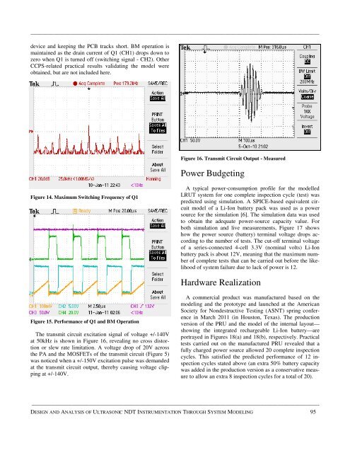
Figure 16. Transmit Circuit Output - Measured<br />
Power Budgeting<br />
Figure 14. Maximum Switching Frequency <strong>of</strong> Q1<br />
A typical power-consumption pr<strong>of</strong>ile for the modelled<br />
LRUT system for one complete inspection cycle (test) was<br />
predicted using simulation. A SPICE-based equivalent circuit<br />
model <strong>of</strong> a Li-Ion battery pack was used as a power<br />
source for the simulation [6]. The simulation data was used<br />
to obtain the adequate power-source capacity value. For<br />
both simulation <strong>and</strong> live measurements, Figure 17 shows<br />
how the power source (battery) terminal voltage drops according<br />
to the number <strong>of</strong> tests. The cut-<strong>of</strong>f terminal voltage<br />
<strong>of</strong> a series-connected 4-cell 3.3V (nominal volts) Li-Ion<br />
battery pack is about 12V, meaning that the maximum number<br />
<strong>of</strong> complete tests that can be carried out before the likelihood<br />
<strong>of</strong> system failure due to lack <strong>of</strong> power is 12.<br />
Hardware Realization<br />
Figure 15. Performance <strong>of</strong> Q1 <strong>and</strong> BM Operation<br />
The transmit circuit excitation signal <strong>of</strong> voltage +/-140V<br />
at 50kHz is shown in Figure 16, revealing no cross distortion<br />
or slew rate limitation. A voltage drop <strong>of</strong> 20V across<br />
the PA <strong>and</strong> the MOSFETs <strong>of</strong> the transmit circuit (Figure 5)<br />
was noticed when a +/-150V excitation pulse was dem<strong>and</strong>ed<br />
at the transmit circuit output, thereby causing voltage clipping<br />
at +/-140V.<br />
A commercial product was manufactured based on the<br />
modeling <strong>and</strong> the prototype <strong>and</strong> launched at the American<br />
Society for Nondestructive Testing (ASNT) spring conference<br />
in March 2011 (in Houston, Texas). The production<br />
version <strong>of</strong> the PRU <strong>and</strong> the model <strong>of</strong> the internal layout—<br />
showing the integrated rechargeable Li-Ion battery—are<br />
portrayed in Figures 18(a) <strong>and</strong> 18(b), respectively. Practical<br />
tests carried out on the manufactured PRU revealed that a<br />
fully charged power source allowed 20 complete inspection<br />
cycles. This satisfied the predicted performance <strong>of</strong> 12 inspection<br />
cycles stated above (an extra 50% battery capacity<br />
was added in the production version as a conservative measure<br />
to allow an extra 8 inspection cycles for a total <strong>of</strong> 20).<br />
——————————————————————————————————————————————————-<br />
DESIGN AND ANALYSIS OF ULTRASONIC <strong>NDT</strong> INSTRUMENTATION THROUGH SYSTEM MODELING 95