06-065 Mini ECO-i II for ARGO - Package
06-065 Mini ECO-i II for ARGO - Package
06-065 Mini ECO-i II for ARGO - Package

You also want an ePaper? Increase the reach of your titles
YUMPU automatically turns print PDFs into web optimized ePapers that Google loves.
<strong>06</strong>-<strong>06</strong>5 <strong>Mini</strong> <strong>ECO</strong>-i <strong>II</strong> <strong>for</strong> <strong>ARGO</strong> 2/8/<strong>06</strong> 4:37 PM Page a<br />
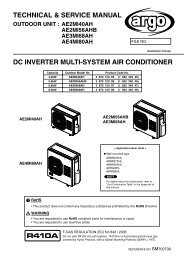
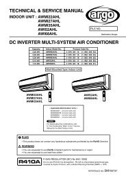
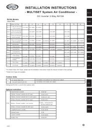
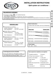
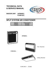
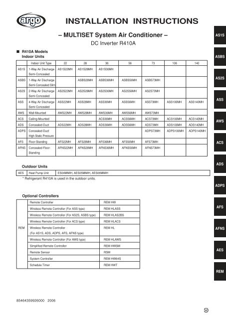
INSTALLATION INSTRUCTIONS<br />
– MULTISET System Air Conditioner –<br />
DC Inverter R410A<br />
AS1S<br />
■ R410A Models<br />
Indoor Units<br />
ASBS<br />
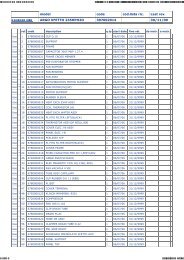
Indoor Unit Type 22 28 36 56 73 1<strong>06</strong> 140<br />
AS1S 1-Way Air Discharge AS1S22MH AS1S28MH AS1S36MH<br />
Semi-Concealed<br />
ASBS 1-Way Air Discharge ASBS28MH ASBS36MH ASBS56MH ASBS73MH<br />
Semi-Concealed Slim<br />
AS2S 2-Way Air Discharge AS2S22MH AS2S28MH AS2S36MH AS2S56MH AS2S73MH<br />
Semi-Concealed<br />
ASS 4-Way Air Discharge ASS22MH ASS28MH ASS36MH ASS56MH ASS73MH ASS1<strong>06</strong>MH ASS140MH<br />
Semi-Concealed<br />
AS2S<br />
ASS<br />
AWS Wall-Mounted AWS22MH AWS28MH AWS36MH AWS56MH AWS73MH<br />
ACS Ceiling-Mounted ACS36MH ACS56MH ACS73MH ACS1<strong>06</strong>MH ACS140MH<br />
ADS Concealed-Duct ADS22MH ADS28MH ADS36MH ADS56MH ADS73MH ADS1<strong>06</strong>MH ADS140MH<br />
AWS<br />
ADPS Concealed-Duct ADPS73MH ADPS1<strong>06</strong>MH ADPS140MH<br />
High Static Pressure<br />
AFS Floor-Standing AFS22MH AFS28MH AFS36MH AFS56MH AFS73MH<br />
AFNS Concealed-Floor- AFNS22MH AFNS28MH AFNS36MH AFNS56MH AFNS73MH<br />
Standing<br />
ACS<br />
Outdoor Units<br />
ADS<br />
AES Heat Pump Unit ES04MMIH, AES05MMIH, AES<strong>06</strong>MMIH<br />
* Refrigerant R410A is used in the outdoor units.<br />
ADPS<br />
Optional Controllers<br />
Remote Controller<br />
Wireless Remote Controller (For ASS type)<br />
Wireless Remote Controller (For AS2S, ASBS type)<br />
Wireless Remote Controller (For ACS type)<br />
REM HW<br />
REM HLASS<br />
REM HLAS2BS<br />
REM HLACS<br />
AFS<br />
REM Wireless Remote Controller REM HL<br />
(For AS1S, ADS, ADPS, AFS, AFNS type)<br />
AFNS<br />
Wireless Remote Controller (For AWS type)<br />
Simplified Remote Controller<br />
Remote Sensor<br />
System Controller<br />
Schedule Timer<br />
REM HLAWS<br />
REM HWSM<br />
RSM<br />
REM HW64S<br />
REM HWT<br />
AES<br />
REM<br />
85464359926000 20<strong>06</strong><br />
W
<strong>06</strong>-<strong>06</strong>5 <strong>Mini</strong> <strong>ECO</strong>-i <strong>II</strong> <strong>for</strong> <strong>ARGO</strong> 2/8/<strong>06</strong> 4:37 PM Page 2<br />
IMPORTANT!<br />
Please Read Be<strong>for</strong>e Starting<br />
This air conditioning system meets strict safety and operating<br />
standards. As the installer or service person, it is an important<br />
part of your job to install or service the system so it operates<br />
safely and efficiently.<br />
For safe installation and trouble-free operation, you must:<br />
● Carefully read this instruction booklet be<strong>for</strong>e beginning.<br />
● Follow each installation or repair step exactly as shown.<br />
● Observe all local, state, and national electrical codes.<br />
● This product is intended <strong>for</strong> professional use.<br />
Permission from the power supplier is required when<br />
installing an outdoor unit that is connected to a 16 A distribution<br />
network.<br />
● Pay close attention to all warning and caution notices<br />
given in this manual.<br />
This symbol refers to a hazard or<br />
WARNING unsafe practice which can result<br />
in severe personal injury or death.<br />
This symbol refers to a hazard or<br />
CAUTION unsafe practice which can result<br />
in personal injury or product or<br />
property damage.<br />
If Necessary, Get Help<br />
These instructions are all you need <strong>for</strong> most installation<br />
sites and maintenance conditions. If you require help <strong>for</strong> a<br />
special problem, contact our sales/service outlet or your<br />
certified dealer <strong>for</strong> additional instructions.<br />
In Case of Improper Installation<br />
The manufacturer shall in no way be responsible <strong>for</strong><br />
improper installation or maintenance service, including failure<br />
to follow the instructions in this document.<br />
SPECIAL PRECAUTIONS<br />
WARNING<br />
When Wiring<br />
ELECTRICAL SHOCK CAN CAUSE<br />
SEVERE PERSONAL INJURY OR DEATH.<br />
ONLY A QUALIFIED, EXPERIENCED<br />
ELECTRICIAN SHOULD ATTEMPT TO<br />
WIRE THIS SYSTEM.<br />
• Do not supply power to the unit until all wiring and tubing<br />
are completed or reconnected and checked.<br />
• Highly dangerous electrical voltages are used in this system.<br />
Carefully refer to the wiring diagram and these<br />
instructions when wiring. Improper connections and inadequate<br />
grounding can cause accidental injury or death.<br />
• Ground the unit following local electrical codes.<br />
• Connect all wiring tightly. Loose wiring may cause overheating<br />
at connection points and a possible fire hazard.<br />
When Transporting<br />
When Installing…<br />
…In a Room<br />
Properly insulate any tubing run inside a room to prevent<br />
“sweating” that can cause dripping and water damage to<br />
walls and floors.<br />
…In Moist or Uneven Locations<br />
Use a raised concrete pad or concrete blocks to provide a<br />
solid, level foundation <strong>for</strong> the outdoor unit. This prevents<br />
water damage and abnormal vibration.<br />
…In an Area with High Winds<br />
Securely anchor the outdoor unit down with bolts and a<br />
metal frame. Provide a suitable air baffle.<br />
…In a Snowy Area (<strong>for</strong> Heat Pump-type Systems)<br />
Install the outdoor unit on a raised plat<strong>for</strong>m that is higher<br />
than drifting snow. Provide snow vents.<br />
When Connecting Refrigerant Tubing<br />
• Ventilate the room well, in the event that is refrigerant<br />
gas leaks during the installation. Be careful not to allow<br />
contact of the refrigerant gas with a flame as this will<br />
cause the generation of poisonous gas.<br />
• Keep all tubing runs as short as possible.<br />
• Use the flare method <strong>for</strong> connecting tubing.<br />
• Apply refrigerant lubricant to the matching surfaces of<br />
the flare and union tubes be<strong>for</strong>e connecting them, then<br />
tighten the nut with a torque wrench <strong>for</strong> a leak-free connection.<br />
• Check carefully <strong>for</strong> leaks be<strong>for</strong>e starting the test run.<br />
When Servicing<br />
• Turn the power OFF at the main power box (mains)<br />
be<strong>for</strong>e opening the unit to check or repair electrical parts<br />
and wiring.<br />
• Keep your fingers and clothing away from any moving<br />
parts.<br />
• Clean up the site after you finish, remembering to check<br />
that no metal scraps or bits of wiring have been left<br />
inside the unit being serviced.<br />
CAUTION<br />
• Ventilate any enclosed areas when installing or testing<br />
the refrigeration system. Escaped refrigerant gas, on<br />
contact with fire or heat, can produce dangerously toxic<br />
gas.<br />
• Confirm after installation that no refrigerant gas is leaking.<br />
If the gas comes in contact with a burning stove, gas<br />
water heater, electric room heater or other heat source,<br />
it can cause the generation of poisonous gas.<br />
Be careful when picking up and moving the indoor and outdoor<br />
units. Get a partner to help, and bend your knees when lifting to<br />
reduce strain on your back. Sharp edges or thin aluminum fins<br />
on the air conditioner can cut your fingers.<br />
2
<strong>06</strong>-<strong>06</strong>5 <strong>Mini</strong> <strong>ECO</strong>-i <strong>II</strong> <strong>for</strong> <strong>ARGO</strong> 2/8/<strong>06</strong> 4:37 PM Page 3<br />
Check of Density Limit<br />
The room in which the air conditioner is to be<br />
installed requires a design that in the event of<br />
refrigerant gas leaking out, its density will not<br />
exceed a set limit.<br />
The refrigerant (R410A), which is used in the air conditioner,<br />
is safe, without the toxicity or combustibility of<br />
ammonia, and is not restricted by laws imposed to protect<br />
the ozone layer. However, since it contains more<br />
than air, it poses the risk of suffocation if its density<br />
should rise excessively. Suffocation from leakage of<br />
refrigerant is almost non-existent. With the recent<br />
increase in the number of high density buildings, however,<br />
the installation of multi air conditioner systems is<br />
on the increase because of the need <strong>for</strong> effective use<br />
of floor space, individual control, energy conservation<br />
by curtailing heat and carrying power, etc.<br />
Most importantly, the multi air conditioner system is<br />
able to replenish a large amount of refrigerant compared<br />
to conventional individual air conditioners. If a<br />
single unit of the multi air conditioner system is to be<br />
installed in a small room, select a suitable model and<br />
installation procedure so that if the refrigerant accidentally<br />
leaks out, its density does not reach the limit<br />
(and in the event of an emergency, measures can be<br />
made be<strong>for</strong>e injury can occur).<br />
In a room where the density may exceed the limit,<br />
create an opening with adjacent rooms, or install<br />
mechanical ventilation combined with a gas leak<br />
detection device. The density is as given below.<br />
Total amount of refrigerant (kg)<br />
Min. volume of the indoor unit installed room (m 3 )<br />
< Density limit (kg/m 3 )<br />
The density limit of refrigerant which is used in multi air conditioners<br />
is 0.3 kg/m 3 (ISO 5149).<br />
NOTE<br />
1. If there are 2 or more refrigerating systems in a single<br />
refrigerating device, the amount of refrigerant<br />
should be as charged in each independent device.<br />
For the amount of charge in this example:<br />
2. The standards <strong>for</strong> minimum room volume are as<br />
follows.<br />
(1) No partition (shaded portion)<br />
(2) When there is an effective opening with the adjacent<br />
room <strong>for</strong> ventilation of leaking refrigerant gas<br />
(opening without a door, or an opening 0.15% or<br />
larger than the respective floor spaces at the top<br />
or bottom of the door).<br />
Outdoor unit<br />
Refrigerant tubing<br />
Indoor unit<br />
(3) If an indoor unit is installed in each partitioned<br />
room and the refrigerant tubing is interconnected,<br />
the smallest room of course becomes the object.<br />
But when mechanical ventilation is installed interlocked<br />
with a gas leakage detector in the smallest<br />
room where the density limit is exceeded, the volume<br />
of the next smallest room becomes the object.<br />
Very<br />
small<br />
room<br />
Small<br />
room<br />
Medium<br />
room<br />
Refrigerant tubing<br />
Large room<br />
Outdoor unit<br />
Indoor unit<br />
Mechanical ventilation device – Gas leak detector<br />
3. The minimum indoor floor space compared with the<br />
amount of refrigerant is roughly as follows (when<br />
the ceiling is 2.7 m high):<br />
e.g., charged<br />
amount (10 kg)<br />
Indoor unit<br />
Outdoor unit<br />
e.g., charged<br />
amount (15 kg)<br />
Room A Room B Room C Room D Room E Room F<br />
The possible amount of leaked refrigerant gas in rooms<br />
A, B and C is 10 kg.<br />
The possible amount of leaked refrigerant gas in rooms<br />
D, E and F is 15 kg.<br />
m 2<br />
Min. indoor floor space<br />
40<br />
35<br />
30<br />
25<br />
20<br />
15<br />
10<br />
5<br />
0<br />
Range below the<br />
density limit<br />
of 0.3 kg/m 3<br />
(countermeasures<br />
not needed)<br />
Range above<br />
the density limit<br />
of 0.3 kg/m 3<br />
(countermeasures<br />
needed)<br />
10 20 30<br />
Total amount of refrigerant<br />
kg<br />
3
<strong>06</strong>-<strong>06</strong>5 <strong>Mini</strong> <strong>ECO</strong>-i <strong>II</strong> <strong>for</strong> <strong>ARGO</strong> 2/8/<strong>06</strong> 4:37 PM Page 4<br />
Precautions <strong>for</strong> Installation Using New Refrigerant<br />
1. Care regarding tubing<br />
1-1. Process tubing<br />
● Material: Use C1220 phosphorous deoxidized copper specified in JIS H3300 “Copper and Copper Alloy Seamless<br />
Pipes and Tubes.”<br />
● Tubing size: Be sure to use the sizes indicated in the table below.<br />
● Use a tube cutter when cutting the tubing, and be sure to remove any flash. This also applies to distribution<br />
joints (optional).<br />
● When bending tubing, use a bending radius that is 4 times the outer diameter of the tubing or larger.<br />
CAUTION<br />
Use sufficient care in handling the tubing. Seal the tubing ends with<br />
caps or tape to prevent dirt, moisture, or other <strong>for</strong>eign substances<br />
from entering. These substances can result in system malfunction.<br />
Copper tube<br />
Unit: mm<br />
Material<br />
O<br />
Outer diameter 6.35 9.52 12.7 15.88 19.05<br />
Wall thickness 0.8 0.8 0.8 1.0 1.0<br />
1-2. Prevent impurities including water, dust and oxide from entering the tubing. Impurities can cause R410A<br />
refrigerant deterioration and compressor defects. Due to the features of the refrigerant and refrigerating<br />
machine oil, the prevention of water and other impurities becomes more important than ever.<br />
2. Be sure to recharge the refrigerant only in liquid <strong>for</strong>m.<br />
2-1. Since R410A is a non-azeotrope, recharging the refrigerant in gas <strong>for</strong>m can lower per<strong>for</strong>mance and cause<br />
defects of the unit.<br />
2-2. Since refrigerant composition changes and per<strong>for</strong>mance decreases when gas leaks, collect the remaining<br />
refrigerant and recharge the required total amount of new refrigerant after fixing the leak.<br />
3. Different tools required<br />
3-1. Tool specifications have been changed due to the characteristics of R410A.<br />
Some tools <strong>for</strong> R22- and R407C-type refrigerant systems cannot be used.<br />
Item<br />
R407C tools<br />
New<br />
compatible<br />
tool?<br />
with R410A?<br />
Remarks<br />
Manifold gauge Yes No Types of refrigerant, refrigerating machine oil, and<br />
pressure gauge are different.<br />
Charge hose Yes No To resist higher pressure, material must be changed.<br />
Vacuum pump Yes Yes Use a conventional vacuum pump if it is equipped<br />
with a check valve. If it has no check valve,<br />
purchase and attach a vacuum pump adapter.<br />
Leak detector Yes No Leak detectors <strong>for</strong> CFC and HCFC that<br />
react to chlorine do not function because<br />
R410A contains no chlorine. Leak detector<br />
<strong>for</strong> HFC134a can be used <strong>for</strong> R410A.<br />
Flaring oil Yes No For systems that use R22, apply mineral oil (Suniso oil)<br />
to the flare nuts on the tubing to prevent refrigerant<br />
leakage. For machines that use R407C or R410A, apply<br />
synthetic oil (ether oil) to the flare nuts.<br />
Manifold gauge<br />
Vacuum pump<br />
Outlet<br />
Inlet<br />
* Using tools <strong>for</strong> R22 and R407C and new tools <strong>for</strong> R410A together can cause defects.<br />
4
<strong>06</strong>-<strong>06</strong>5 <strong>Mini</strong> <strong>ECO</strong>-i <strong>II</strong> <strong>for</strong> <strong>ARGO</strong> 2/8/<strong>06</strong> 4:37 PM Page 5<br />
3-2. Use R410A exclusive cylinder only.<br />
Valve<br />
Single-outlet valve<br />
(with siphon tube)<br />
Liquid refrigerant should be recharged<br />
with the cylinder standing on end as<br />
shown.<br />
Liquid<br />
5
<strong>06</strong>-<strong>06</strong>5 <strong>Mini</strong> <strong>ECO</strong>-i <strong>II</strong> <strong>for</strong> <strong>ARGO</strong> 2/8/<strong>06</strong> 4:37 PM Page 6<br />
IMPORTANT . . . . . . . . . . . . . . . . . . . . . . . . . . . . . . 2<br />
Please Read Be<strong>for</strong>e Starting<br />
Check of Density Limit<br />
Precautions <strong>for</strong> Installation Using New Refrigerant<br />
1. GENERAL . . . . . . . . . . . . . . . . . . . . . . . . . . . . . 8<br />
1-1. Tools Required <strong>for</strong> Installation (not supplied)<br />
1-2. Accessories Supplied with Unit<br />
1-3. Type of Copper Tube and Insulation Material<br />
1-4. Additional Materials Required <strong>for</strong> Installation<br />
1-5. Tubing Size<br />
1-6. Straight Equivalent Length of Joints<br />
1-7. Additional Refrigerant Charge<br />
1-8. System Limitations<br />
1-9. Tubing Length<br />
1-10. Check of Limit Density<br />
1-11. Installing Distribution Joint<br />
1-12 Optional Distribution Joint Kit<br />
1-13. Optional Ball Valve Kit<br />
1-14. Recommended Location of Ball Valves<br />
1-15. Example of Tubing Size Selection and<br />
Refrigerant Charge Amount<br />
2. SELECTING THE INSTALLATION SITE . . . . .21<br />
2-1. Indoor Unit<br />
2-2. Outdoor Unit<br />
2-3. Air Discharge Chamber <strong>for</strong> Top Discharge<br />
2-4. Installing the Unit in Heavy Snow Areas<br />
2-5. Precautions <strong>for</strong> Installation in Heavy Snow<br />
Areas<br />
2-6. Dimensions of Air-Discharge Chamber<br />
2-7. Dimensions of Outdoor Unit with<br />
Air-Discharge Chamber (field supply)<br />
2-8. Dimensions of Snow Ducting<br />
2-9. Dimensions of Outdoor Unit with<br />
Snow-Proof Vents (field supply)<br />
3. HOW TO INSTALL THE INDOOR UNIT . . . . . .29<br />
■ 1-Way Air Discharge Semi-Concealed Type<br />
(AS1S Type) . . . . . . . . . . . . . . . . . . . . . . . . . . .29<br />
3-1. Suspending the Indoor Unit<br />
3-2. Placing the Unit Inside the Ceiling<br />
3-3. Installing the Drain Piping<br />
3-4. Checking the Drainage<br />
■ 1-Way Air Discharge Semi-Concealed Slim Type<br />
(ASBS Type) . . . . . . . . . . . . . . . . . . . . . . . . . . .34<br />
3-5. Suspending the Indoor Unit<br />
3-6. Placing the Unit Inside the Ceiling<br />
3-7. Installing the Drain Piping<br />
3-8. Checking the Drainage<br />
■ 2-Way Air Discharge Semi-Concealed Type<br />
(AS2S Type) . . . . . . . . . . . . . . . . . . . . . . . . . . .39<br />
3-9. Suspending the Indoor Unit<br />
3-10. Placing the Unit Inside the Ceiling<br />
CONTENTS<br />
Page<br />
6<br />
3-11. Installing the Drain Piping<br />
3-12. Checking the Drainage<br />
Page<br />
■ 4-Way Air Discharge Semi-Concealed Type<br />
(ASS Type) . . . . . . . . . . . . . . . . . . . . . . . . . . . .43<br />
3-13. Preparation <strong>for</strong> Suspending<br />
3-14. Suspending the Indoor Unit<br />
3-15. Placing the Unit Inside the Ceiling<br />
3-16. Installing the Drain Piping<br />
3-17. Checking the Drainage<br />
■ Wall-Mounted Type (AWS Type) . . . . . . . . . . . .47<br />
3-18. Removing the Rear Panel from the Unit<br />
3-19. Selecting and Making a Hole<br />
3-20. Installing the Rear Panel onto the Wall<br />
3-21. Removing the Grille to Install the Indoor Unit<br />
3-22. Preparing the Tubing<br />
3-23. Shaping the Tubing<br />
3-24. Installing the Drain Hose<br />
■ Ceiling-Mounted Type (ACS Type) . . . . . . . . . .51<br />
3-25. Required <strong>Mini</strong>mum Space <strong>for</strong> Installation and<br />
Service<br />
3-26. Suspending the Indoor Unit<br />
3-27. Duct <strong>for</strong> Fresh Air<br />
3-28. Shaping the Tubing<br />
3-29. Installing the Drain Piping<br />
■ Concealed-Duct Type (ADS Type) . . . . . . . . . .58<br />
3-30. Required <strong>Mini</strong>mum Space <strong>for</strong> Installation and<br />
Service<br />
3-31. Suspending the Indoor Unit<br />
3-32. Installing the Drain Piping<br />
3-33. Checking the Drainage<br />
3-34. Increasing the Fan Speed<br />
■ Concealed-Duct High Static Pressure Type<br />
(ADPS Type) . . . . . . . . . . . . . . . . . . . . . . . . . . .63<br />
3-35. Required <strong>Mini</strong>mum Space <strong>for</strong> Installation and<br />
Service (73, 1<strong>06</strong>, 140 Type)<br />
3-36. Suspending the Indoor Unit<br />
3-37. Installing the Drain Piping<br />
3-38. Caution <strong>for</strong> Ducting Work<br />
■ Floor-Standing Type (AFS Type)<br />
Concealed Floor-Standing Type (AFNS Type) . . .67<br />
3-39. Required <strong>Mini</strong>mum Space <strong>for</strong> Installation and<br />
Service<br />
3-40. Dimensions and Part Names<br />
3-41. Removing and Attaching the Front Panel<br />
(Floor-Standing Type)<br />
3-42. Installing the Refrigerant Tubing<br />
3-43. Installing the Drain Piping<br />
3-44. Installing the Remote Controller<br />
4. HOW TO INSTALL THE OUTDOOR UNIT . . . .72<br />
4-1. Installing the Outdoor Unit<br />
4-2. Drainage Work<br />
4-3. Routing the Tubing and Wiring
<strong>06</strong>-<strong>06</strong>5 <strong>Mini</strong> <strong>ECO</strong>-i <strong>II</strong> <strong>for</strong> <strong>ARGO</strong> 2/8/<strong>06</strong> 4:37 PM Page 7<br />
5. ELECTRICAL WIRING . . . . . . . . . . . . . . . . . . .73<br />
5-1. General Precautions on Wiring<br />
5-2. Recommended Wire Length and Wire<br />
Diameter <strong>for</strong> Power Supply System<br />
5-3. Wiring System Diagrams<br />
6. HOW TO INSTALL THE REMOTE CONTROLLER<br />
(OPTIONAL PART) . . . . . . . . . . . . . . . . . . . . . .77<br />
6-1. When Using a Wall Box <strong>for</strong> Flush Mounting<br />
6-2. Basic Wiring Diagram<br />
6-3. Wiring System Diagram <strong>for</strong> Group Control<br />
6-4. Switching the Room Temperature Sensors<br />
6-5. Connecting to a Ventilation Fan<br />
6-6. Wiring the Remote Controller<br />
7. HOW TO PROCESS TUBING . . . . . . . . . . . . .82<br />
7-1. Connecting the Refrigerant Tubing<br />
7-2. Connecting Tubing Between Indoor and<br />
Outdoor Units<br />
7-3. Insulating the Refrigerant Tubing<br />
7-4. Taping the Tubes<br />
7-5. Finishing the Installation<br />
8. AIR PURGING . . . . . . . . . . . . . . . . . . . . . . . . .86<br />
■ Air Purging with a Vacuum Pump (<strong>for</strong> Test Run)<br />
Preparation<br />
Page<br />
9. HOW TO INSTALL THE CEILING PANEL . . . .89<br />
■ 1-Way Air Discharge Semi-Concealed Type<br />
(AS1S Type) . . . . . . . . . . . . . . . . . . . . . . . . . . .89<br />
9-1. Installing the Ceiling Panel<br />
9-2. How to Use the Stoppers<br />
■ 1-Way Air Discharge Semi-Concealed Slim Type<br />
(ASBS Type) . . . . . . . . . . . . . . . . . . . . . . . . . . .90<br />
9-3. Installing the Ceiling Panel<br />
■ 2-Way Air Discharge Semi-Concealed Type<br />
(AS2S Type) . . . . . . . . . . . . . . . . . . . . . . . . . . .92<br />
9-4. Be<strong>for</strong>e Installing the Ceiling Panel<br />
9-5. Installing the Ceiling Panel<br />
9-6. When Removing the Ceiling Panel <strong>for</strong> Servicing<br />
■ 4-Way Air Discharge Semi-Concealed Type<br />
(ASS Type) . . . . . . . . . . . . . . . . . . . . . . . . . . . .94<br />
9-7. Be<strong>for</strong>e Installing the Ceiling Panel<br />
9-8. Installing the Ceiling Panel<br />
9-9. Wiring the Ceiling Panel<br />
9-10. How to Attach the Corner & Air Intake Grille<br />
9-11. Checking After Installation<br />
9-12. When Removing the Ceiling Panel <strong>for</strong> Servicing<br />
9-13. Adjusting the Auto Flap<br />
10. TEST RUN . . . . . . . . . . . . . . . . . . . . . . . . . . . .98<br />
10-1. Preparing <strong>for</strong> Test Run<br />
10-2. Test Run Procedure<br />
10-3. Outdoor Unit PCB Setting<br />
10-4. Auto Address Setting<br />
10-5. Caution <strong>for</strong> Pump Down<br />
10-6. Meaning of Alarm Messages<br />
11. HOW TO INSTALL THE WIRELESS REMOTE<br />
CONTROLLER RECEIVER . . . . . . . . . . . . . .111<br />
■ REM HLASS <strong>for</strong> 4-Way Cassette (ASS Type) . . .111<br />
11-1. Installing the Receiver Unit<br />
11-2. Accessories<br />
11-3. Wiring the Receiver Unit<br />
11-4. Precautions on Simultaneous Installation of<br />
Wired Remote Controller and Wireless<br />
Remote Controller<br />
11-5. How to use the Test Run Setting<br />
■ REM HLACS <strong>for</strong> Ceiling Mounted (ACS Type) . . .114<br />
11-6. Installing the Receiver Unit<br />
11-7. Accessories Supplied with Unit<br />
11-8. Wiring the Receiver Unit<br />
11-9. Precautions on Simultaneous Installation of<br />
Wired Remote Controller and Wireless<br />
Remote Controller<br />
11-10. How to Use the Test Run Setting<br />
■ REM HLAS2BS <strong>for</strong> 2-Way and High Ceiling<br />
1-Way Type (AS2S, ASBS Type) . . . . . . . . . . .117<br />
11-11. Installing the Display<br />
11-12. Installing the Control Unit<br />
11-13. Installing the Display<br />
11-14. Installing the Control Unit<br />
11-15. Accessories<br />
11-16. Wiring the Receiver Unit<br />
11-17. Precautions on Simultaneous Installation of<br />
Wired Remote Controller and Wireless<br />
Remote Controller<br />
11-18. How to Use the Test Run Setting<br />
■ REM HL <strong>for</strong> AS1S, ADS, ADPS, AFS, AFNS Type<br />
. . . . . . . . . . . . . . . . . . . . . . . . . . . . . . . .122<br />
11-19. Accessories Supplied with Separate<br />
Receiver Unit<br />
11-20. Important In<strong>for</strong>mation <strong>for</strong> Installation of<br />
1 Separate Receiver Unit<br />
11-21. How to Install the Separate Receiver Unit<br />
11-22. Wiring the Separate Receiver Unit<br />
11-23. . . .Important In<strong>for</strong>mation <strong>for</strong> Installation of<br />
2 Separate Receiver Units<br />
11-24. Test Run Setting<br />
12. SPECIAL REMARKS . . . . . . . . . . . . . . . . . . .128<br />
■ DC Fan Tap Change Procedure <strong>for</strong> 4-Way<br />
Cassete (ASS Type)<br />
Page<br />
13. MARKINGS FOR DIRECTIVE<br />
97/23/EC(PED) . . . . . . . . . . . . . . . . . . . . . . . 129<br />
7
<strong>06</strong>-<strong>06</strong>5 <strong>Mini</strong> <strong>ECO</strong>-i <strong>II</strong> <strong>for</strong> <strong>ARGO</strong> 2/8/<strong>06</strong> 4:37 PM Page 8<br />
1. GENERAL<br />
This booklet briefly outlines where and how to install<br />
the air conditioning system. Please read over the<br />
entire set of instructions <strong>for</strong> the indoor and outdoor<br />
units and make sure all accessory parts listed are<br />
with the system be<strong>for</strong>e beginning.<br />
CAUTION<br />
Check local electrical codes<br />
and regulations be<strong>for</strong>e<br />
obtaining wire. Also, check<br />
any specified instructions<br />
or limitations.<br />
1-1. Tools Required <strong>for</strong> Installation (not supplied)<br />
1. Standard screwdriver<br />
2. Phillips head screwdriver<br />
3. Knife or wire stripper<br />
4. Tape measure<br />
5. Carpenter’s level<br />
6. Sabre saw or key hole saw<br />
7. Hacksaw<br />
8. Core bits<br />
9. Hammer<br />
10. Drill<br />
11. Tube cutter<br />
12. Tube flaring tool<br />
13. Torque wrench<br />
14. Adjustable wrench<br />
15. Reamer (<strong>for</strong> deburring)<br />
1-4. Additional Materials Required <strong>for</strong> Installation<br />
1. Refrigeration (armored) tape<br />
2. Insulated staples or clamps <strong>for</strong> connecting wire<br />
(See your local codes.)<br />
3. Putty<br />
4. Refrigeration tubing lubricant<br />
5. Clamps or saddles to secure refrigerant tubing<br />
6. Scale <strong>for</strong> weighing<br />
1-2. Accessories Supplied with Unit<br />
See Tables 1-1 to 1-10.<br />
Table<br />
Type<br />
1-1 1-Way Air Discharge Semi-Concealed<br />
1-2 1-Way Air Discharge Semi-Concealed Slim<br />
1-3 2-Way Air Discharge Semi-Concealed<br />
1-4 4-Way Air Discharge Semi-Concealed<br />
1-5 Wall-Mounted<br />
1-6 Ceiling-Mounted<br />
1-7 Concealed-Duct<br />
1-8 Concealed-Duct High Static Pressure<br />
1-9 Floor-Standing & Concealed Floor-Standing<br />
1-10 Outdoor Unit<br />
1-3. Type of Copper Tube and Insulation Material<br />
If you wish to purchase these materials separately<br />
from a local source, you will need:<br />
1. Deoxidized annealed copper tube <strong>for</strong> refrigerant<br />
tubing.<br />
2. Foamed polyethylene insulation <strong>for</strong> copper tubes as<br />
required to precise length of tubing. Wall thickness<br />
of the insulation should be not less than 8 mm.<br />
3. Use insulated copper wire <strong>for</strong> field wiring. Wire<br />
size varies with the total length of wiring. Refer to<br />
5. Electrical Wiring <strong>for</strong> details.<br />
8
<strong>06</strong>-<strong>06</strong>5 <strong>Mini</strong> <strong>ECO</strong>-i <strong>II</strong> <strong>for</strong> <strong>ARGO</strong> 2/8/<strong>06</strong> 4:37 PM Page 9<br />
Table 1-1 (1-Way Air Discharge Semi-Concealed)<br />
Part Name Figure Q’ty Remarks<br />
Flare insulator 2<br />
For gas and liquid tubes<br />
Insulating tape<br />
(Black)<br />
(White)<br />
3<br />
2<br />
For gas and liquid tubes<br />
For gas and liquid tube flare nuts<br />
Vinyl clamp 8<br />
Hose band 1<br />
Packing 1<br />
For flare insulator<br />
For securing drain hose<br />
For drain joint<br />
Drain insulator 1 For drain joint<br />
Drain hose<br />
1 For securing drain hose<br />
Installation gauge<br />
1<br />
For measuring clearance between the unit and ceiling<br />
Special washer<br />
8<br />
For suspension bolts<br />
Table 1-2 (1-Way Air Discharge Semi-Concealed Slim)<br />
Part Name Figure Q’ty Remarks<br />
Full-scale installation diagram 1<br />
Special washer 8<br />
Flare insulator 2<br />
(Black) 2<br />
Insulating tape<br />
(White) 2<br />
Vinyl clamp 8<br />
Hose band 1<br />
Packing 1<br />
Drain insulator 1<br />
Sealing putty 1<br />
Cable 1<br />
Drain hose 1<br />
For determining suspension bolt pitch<br />
For temporarily suspending indoor unit from ceiling<br />
For gas and liquid tubes<br />
For gas and liquid tubes<br />
For gas and liquid tube flare nuts<br />
For flare insulator<br />
For securing drain hose<br />
For drain joint<br />
For drain joint<br />
For sealing recessed portion of power supply<br />
Connection cable <strong>for</strong> fan motor<br />
For securing drain hose<br />
9
<strong>06</strong>-<strong>06</strong>5 <strong>Mini</strong> <strong>ECO</strong>-i <strong>II</strong> <strong>for</strong> <strong>ARGO</strong> 2/8/<strong>06</strong> 4:37 PM Page 10<br />
Table 1-3 (2-Way Air Discharge Semi-Concealed)<br />
Part Name Figure Q’ty Remarks<br />
Flare insulator 2 For gas and liquid tubes<br />
Insulating tape (White) 2<br />
Vinyl clamp 8<br />
Hose band 1<br />
Packing 1<br />
Drain insulator 1<br />
Installation gauge<br />
(Use the packaging side pad.)<br />
M5 × L40 (Black screw, with washer)<br />
Special washer<br />
1<br />
1<br />
4<br />
8<br />
For gas and liquid tube flare nuts<br />
For flare insulator and drain insulator<br />
For securing drain hose<br />
For drain joint<br />
For drain joint<br />
Gauge A<br />
(Install on tubing side.)<br />
Gauge B<br />
(Install on opposite side of tubing.)<br />
For fastening installation gauges<br />
For suspension bolts<br />
Drain hose (L = 25cm)<br />
1<br />
For securing drain hose<br />
Putty<br />
1 For sealing recessed portion of power supply<br />
Table 1-4 (4-Way Air Discharge Semi-Concealed)<br />
Part Name Figure Q’ty Remarks<br />
Full-scale installation diagram 1 Printed on container box<br />
Flare insulator 2<br />
Insulating tape (White) 2<br />
Hose band 1<br />
Packing 1<br />
For gas and liquid tubes<br />
For gas and liquid tube flare nuts<br />
For securing drain hose<br />
For drain joint<br />
Drain insulator 1 For drain joint<br />
Drain hose 1 For securing drain hose<br />
Washer 8 For suspension bolts<br />
Screw<br />
4<br />
For full-scale installation diagram<br />
Table 1-5 (Wall-Mounted)<br />
Part Name Figure Q’ty Remarks<br />
Plastic cover 1<br />
For improved tubing appearance<br />
Tapping screw<br />
Truss-head Phillips<br />
4 × 30 mm<br />
10 For fixing the rear panel<br />
Insulator 1 For insulating flare nut (73 type only)<br />
10
<strong>06</strong>-<strong>06</strong>5 <strong>Mini</strong> <strong>ECO</strong>-i <strong>II</strong> <strong>for</strong> <strong>ARGO</strong> 2/8/<strong>06</strong> 4:37 PM Page 11<br />
Table 1-6 (Ceiling-Mounted)<br />
Part Name Figure Q’ty Remarks<br />
Special washer 4<br />
Drain insulator<br />
T10<br />
1<br />
Flare insulator T5<br />
T3<br />
2 sets<br />
Insulating tape White<br />
(heat-resisting) 2<br />
Vinyl clamp 8<br />
Eyelet 1<br />
For temporarily suspending indoor unit from ceiling<br />
For drain hose joint<br />
For gas and liquid tube joints<br />
For gas and liquid flare joints<br />
For flare and drain insulator<br />
For power supply inlet<br />
Full-scale installation<br />
diagram<br />
1<br />
Printed on container box<br />
Drain hose L140<br />
1<br />
Hose band<br />
2<br />
For main unit + PVC pipe joints<br />
For drain hose connection<br />
Table 1-7 (Concealed-Duct)<br />
Washer<br />
Part Name Figure Q’ty Remarks<br />
8<br />
For suspending indoor unit from ceiling<br />
Flare insulator 2<br />
Insulating tape 2<br />
Drain insulator 1<br />
Hose band 1<br />
Packing 1<br />
For gas and liquid tubes<br />
For gas and liquid tube flare nuts<br />
For drain hose joint<br />
For securing drain hose<br />
For drain joint<br />
Drain hose 1<br />
Sealing putty 1<br />
Vinyl clamp 8<br />
Booster cable* 1<br />
* Booster cable is housed inside the electrical component box.<br />
● Use 3/8" <strong>for</strong> suspending bolts.<br />
● Field supply <strong>for</strong> suspending bolts and nuts.<br />
For sealing recessed portion of power supply<br />
For flare and drain insulators<br />
Connector <strong>for</strong> changeover to HT tap.<br />
11
<strong>06</strong>-<strong>06</strong>5 <strong>Mini</strong> <strong>ECO</strong>-i <strong>II</strong> <strong>for</strong> <strong>ARGO</strong> 2/8/<strong>06</strong> 4:37 PM Page 12<br />
Table 1-8 (Concealed-Duct High Static Pressure)<br />
Part Name Figure Q’ty Remarks<br />
Special washer 8<br />
Flare insulator 2<br />
Drain socket 1<br />
Tube connector 1<br />
For suspending indoor unit from ceiling<br />
For gas and liquid tubes<br />
For drain pipe connection<br />
For increasing size of liquid tube from ø6.35 to<br />
ø9.52 mm (only <strong>for</strong> 73 type)<br />
Table 1-9 (Floor-Standing & Concealed Floor-Standing)<br />
Part Name Figure Q’ty Remarks<br />
Connection pipe 1<br />
For connecting gas tubes<br />
Flare insulator 2<br />
For gas and liquid tubes<br />
Insulating tape (White) 2<br />
For gas and liquid tube flare nuts<br />
Insulating tape (Black) 2<br />
For gas and liquid tubes<br />
Vinyl clamp 7<br />
For ends of flare insulator<br />
Insulating tape (black and long) 1<br />
For drain pipe<br />
Drain insulator 1<br />
For drain hose joint<br />
Table 1-10 (Outdoor Unit)<br />
Q’ty<br />
Part name<br />
Figure<br />
04 Model<br />
(4 hp)<br />
05 Model<br />
(5 hp)<br />
<strong>06</strong> Model<br />
(6 hp)<br />
Tube Discharge<br />
Assy<br />
0<br />
0<br />
1<br />
Instruction manual<br />
paper<br />
1<br />
1<br />
1<br />
hp = horsepower<br />
12
<strong>06</strong>-<strong>06</strong>5 <strong>Mini</strong> <strong>ECO</strong>-i <strong>II</strong> <strong>for</strong> <strong>ARGO</strong> 2/8/<strong>06</strong> 4:37 PM Page 13<br />
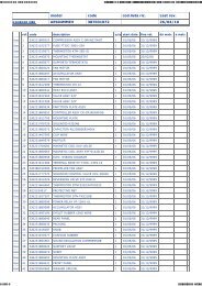
1-5. Tubing Size<br />
Table 1-11 Main Tubing Size (LA)<br />
kW<br />
System<br />
horsepower<br />
Gas tubing<br />
(mm)<br />
Liquid tubing<br />
(mm)<br />
11.2<br />
4<br />
ø15.88<br />
14.0<br />
5<br />
ø9.52<br />
15.5<br />
6<br />
ø19.05<br />
Unit: mm<br />
Note: When only one indoor unit is connected to a 6-hp outdoor unit, connect ø19.05 gas tubing up to just be<strong>for</strong>e the indoor<br />
unit, then use a socket or similar device (field supply) to change the tube diameter to ø15.88 and connect the gas tube<br />
to the indoor unit.<br />
Table 1-12 Main Tubing Size After Distribution (LB, LC...)<br />
Total capacity<br />
after distribution<br />
Tubing size<br />
Below kW<br />
Over kW<br />
Gas tubing (mm)<br />
Liquid tubing (mm)<br />
7.1<br />
(2.5 hp)<br />
–<br />
ø12.7<br />
ø9.52<br />
15.5<br />
(6 hp)<br />
7.1<br />
(2.5 hp)<br />
ø15.88<br />
ø9.52<br />
Unit: mm<br />
hp = horsepower<br />
Note: In case the total capacity of connected indoor units exceeds the total capacity of the outdoor units, select the main<br />
tubing size <strong>for</strong> the total capacity of the outdoor units.<br />
Table 1-13 Indoor Unit Tubing Connection ( 1, 2... n–1)<br />
Indoor unit type 22 28 36 56 73 1<strong>06</strong> 140<br />
Gas tubing (mm) ø12.7<br />
ø15.88<br />
Liquid tubing (mm)<br />
ø6.35<br />
ø9.52 Unit: mm<br />
1-6. Straight Equivalent Length of Joints<br />
Design the tubing system by referring to the following table <strong>for</strong> the straight equivalent length of joints.<br />
Table 1-14 Straight Equivalent Length of Joints<br />
Gas tubing size (mm)<br />
12.7<br />
15.88<br />
19.05<br />
90° elbow<br />
0.30<br />
0.35<br />
0.42<br />
45° elbow<br />
0.23<br />
0.26<br />
0.32<br />
U-shape tube bend (R60 100 mm)<br />
0.90<br />
1.05<br />
1.26<br />
Trap bend<br />
2.30<br />
2.80<br />
3.20<br />
Y-branch distribution joint<br />
Ball valve <strong>for</strong> service<br />
Equivalent length conversion not needed.<br />
Equivalent length conversion not needed.<br />
Table 1-15 Required Copper Tubing Dimensions<br />
Unit: mm<br />
Material<br />
O<br />
Outer diameter 6.35 9.52 12.7 15.88 19.05<br />
Copper tubing<br />
Wall thickness 0.8 0.8 0.8 1.0 1.0<br />
13
<strong>06</strong>-<strong>06</strong>5 <strong>Mini</strong> <strong>ECO</strong>-i <strong>II</strong> <strong>for</strong> <strong>ARGO</strong> 2/8/<strong>06</strong> 4:37 PM Page 14<br />
1-7. Additional Refrigerant Charge<br />
Additional refrigerant charge amount is calculated from the liquid tubing total length as follows.<br />
Table 1-16 Amount of Refrigerant Charge Per Meter, According to Liquid Tubing Size<br />
Liquid tubing size Amount of refrigerant<br />
charge/m (g/m)<br />
Required amount of charge = (Amount of refrigerant<br />
charge per meter of each size of liquid tube × its tube<br />
ø6.35 26<br />
length) + (...) + (...)<br />
ø9.52 56<br />
*Always charge accurately using a scale <strong>for</strong> weighing.<br />
Table 1-17 Refrigerant Charge Amount at Shipment (<strong>for</strong> outdoor unit)<br />
Heat pump unit<br />
(kg)<br />
AES04MMIH<br />
3.5<br />
AES05MMIH<br />
3.5<br />
AES<strong>06</strong>MMIH<br />
3.5<br />
1-8. System Limitations<br />
Table 1-18 System Limitations<br />
Outdoor units (Type) 04 05 <strong>06</strong><br />
Number of max. connectable indoor units<br />
6 8 9<br />
Max. allowable indoor/outdoor capacity ratio 50 – 130%<br />
1-9. Tubing Length<br />
Select the installation location so that the length and size of refrigerant tubing are within the allowable range shown<br />
in the figure below.<br />
Main tube of unit<br />
LA<br />
LB<br />
LC<br />
L1<br />
L2<br />
LD<br />
n<br />
H1<br />
1st branch<br />
Unit distribution tube<br />
L3<br />
1 2 3 n-1<br />
H2<br />
Note: Do not use commercially available T-joints <strong>for</strong> the liquid tubing.<br />
* Be sure to use special R410A distribution joints (DDVI: purchased separately)<br />
<strong>for</strong> outdoor unit connections and tubing branches.<br />
R410A distribution joint<br />
DDVI16 (<strong>for</strong> indoor unit)<br />
Table 1-19 Ranges that Apply to Refrigerant Tubing Lengths and to Differences in Installation Heights<br />
Items Marks Contents Length (m)<br />
Allowable tubing<br />
length<br />
Allowable elevation<br />
difference<br />
L = Length, H = Height<br />
L1<br />
L (L2 – L3)<br />
Max. tubing length<br />
Difference between max. length and min.<br />
length from the No.1 distribution joint<br />
Actual length 150<br />
Equivalent length 175<br />
1, 2 ~ n Max. length of each distribution tube 30<br />
Total max. tubing length including length of<br />
1+ 2 +~ n–1 +L1<br />
each distribution tube (only liquid tubing)<br />
When outdoor unit is installed higher than indoor unit 50<br />
H1<br />
When outdoor unit is installed lower than indoor unit 40<br />
H2 Max. difference between indoor units 15<br />
><br />
><br />
><br />
><br />
><br />
><br />
><br />
><br />
40<br />
200<br />
14
<strong>06</strong>-<strong>06</strong>5 <strong>Mini</strong> <strong>ECO</strong>-i <strong>II</strong> <strong>for</strong> <strong>ARGO</strong> 2/8/<strong>06</strong> 4:37 PM Page 15<br />
WARNING<br />
Always check the gas density<br />
limit <strong>for</strong> the room in<br />
which the unit is installed.<br />
1-10. Check of Limit Density<br />
When installing an air conditioner in a room, it is necessary<br />
to ensure that even if the refrigerant gas accidentally<br />
leaks out, its density does not exceed the limit<br />
level <strong>for</strong> that room.<br />
If the density could exceed the limit level, it is necessary<br />
to provide an opening between the unit and the<br />
adjacent room, or to install mechanical ventilation<br />
which is interlocked with the leak detector.<br />
(Total refrigerant charged amount: kg)<br />
(Min. indoor volume where the indoor unit is installed: m 3 )<br />
< Limit density 0.3 (kg/m 3 )<br />
The limit density of refrigerant which is used in this unit<br />
is 0.3 kg/m 3 (ISO 5149).<br />
The shipped outdoor unit comes charged with the<br />
amount of refrigerant fixed <strong>for</strong> each type, so add it to<br />
the amount that is charged in the field. (For the refrigerant<br />
charge amount at shipment, refer to the unit’s<br />
nameplate.)<br />
<strong>Mini</strong>mum indoor volume & floor area as against the<br />
amount of refrigerant is roughly as given in the following<br />
table.<br />
Min. indoor floor area<br />
(when the ceiling is 2.7 m high)<br />
m 2<br />
100<br />
m 3<br />
270.0<br />
95 256.5<br />
90 243.0<br />
85 229.5 Range below the<br />
80 216.0<br />
density limit of<br />
0.3 kg/m<br />
75 202.5<br />
(Countermeasures<br />
70 189.0 not needed)<br />
65 175.5<br />
60 162.0<br />
55 148.5<br />
50 135.0<br />
Range above the<br />
45 121.5<br />
density limit of<br />
0.3 kg/m<br />
40 108.0<br />
(Countermeasures<br />
35 94.5<br />
needed)<br />
30 81.0<br />
25 67.5<br />
20<br />
15<br />
54.0<br />
40.5<br />
20 30 40 50 60 70 80 kg<br />
Total amount of refrigerant<br />
Min. indoor volume<br />
CAUTION<br />
Pay special attention to any<br />
location, such as a basement,<br />
etc., where leaking refrigerant<br />
can accumulate, since refrigerant<br />
gas is heavier than air.<br />
Tube branching methods (horizontal use)<br />
15 to 30°<br />
1-11. Installing Distribution Joint<br />
(1) Refer to “HOW TO ATTACH DISTRIBUTION<br />
JOINT” enclosed with the optional distribution joint<br />
kit (DDVI16).<br />
(2) In order to prevent accumulation of refrigerant oil in<br />
stopped units, if the main tubing is horizontal then<br />
each branch tubing length should be at an angle that<br />
is greater than horizontal. If the main tubing is vertical,<br />
provide a raised starting portion <strong>for</strong> each branch.<br />
(3) If there are height differences between indoor units<br />
or if branch tubing that follows a distribution joint is<br />
connected to only 1 unit, a trap or ball valve must be<br />
added to that distribution joint. (When adding the ball<br />
valve, locate it within 40 cm of the distribution joint.)<br />
(Consult with <strong>ARGO</strong> separately concerning the ball<br />
valve.)<br />
If a trap or ball valve is not added, do not operate<br />
the system be<strong>for</strong>e repairs to a malfunctioning<br />
unit are completed. (The refrigerant oil sent<br />
through the tubing to the malfunctioning unit will<br />
accumulate and may damage the compressor.)<br />
B<br />
Ball valve<br />
(BV: purchased<br />
separately)<br />
Main tubing<br />
A<br />
Main tubing<br />
Arrow view<br />
B<br />
Horizontal A<br />
line View as seen<br />
from arrow<br />
Types of vertical trap specifications<br />
(When using ball valve)<br />
Indoor unit (1)<br />
Indoor unit (more than 2 units)<br />
(If only 1 unit is connected, a ball<br />
valve is also needed on this side.)<br />
(When not using ball valve)<br />
Horizontal<br />
Indoor unit<br />
Branch tubing is<br />
directed upward.<br />
More than<br />
20 cm<br />
Indoor unit is directed downward<br />
(Each unit is<br />
connected to tubing<br />
that is either level or<br />
is directed<br />
downward.)<br />
15
<strong>06</strong>-<strong>06</strong>5 <strong>Mini</strong> <strong>ECO</strong>-i <strong>II</strong> <strong>for</strong> <strong>ARGO</strong> 2/8/<strong>06</strong> 4:37 PM Page 16<br />
1-12. Optional Distribution Joint Kit<br />
See the installation instructions packaged with the distribution joint kit <strong>for</strong> the installation procedure.<br />
Table 1-20<br />
Model name Cooling capacity after distribution Remarks<br />
DDVI16 22.4 kW or less For indoor unit<br />
DDVI16<br />
Use: For indoor unit (Capacity after distribution joint is 22.4 kW or less.)<br />
Example: (F below indicates inner diameter. F below indicates outer diameter.)<br />
• When creating a tube of diameter G,<br />
use a tube cutter and cut between F<br />
and H. Cut at a point as close to H<br />
as possible.<br />
Gas tube<br />
210 55<br />
103<br />
Liquid tube<br />
185 50<br />
F F<br />
F<br />
H<br />
H<br />
HG<br />
F GH J I<br />
I J<br />
F<br />
F H<br />
I<br />
GH<br />
145 135 J<br />
83<br />
Insulator<br />
Insulator<br />
Table 1-21 Dimension <strong>for</strong> Connections of Each Part<br />
Unit: mm<br />
Position A B C D E F G H I J<br />
Dimension – – – – – ø19.05 ø15.88 ø12.7 ø9.52 ø6.35<br />
1-13. Optional Ball Valve Kit<br />
Table 1-22<br />
Valve connecting tube size (mm)<br />
Model No.<br />
Gas tube Liquid tube<br />
BV-RXP160AG 15.88<br />
9.52<br />
BV-RXP56AG 12.7<br />
6.35<br />
Indoor unit where used<br />
Total capacity of indoor units<br />
after the valve<br />
16.0 kW or less<br />
5.6 kW or less<br />
NOTE<br />
1. Because the diameter of this ball valve is approximately the same as the inner diameter of the connecting copper<br />
tube, correction <strong>for</strong> pressure loss is not necessary.<br />
2. Airtightness must be 3.6 MPa or more.<br />
It is recommended that the ball valve is installed at each outdoor unit (gas tube and liquid tube), in order to<br />
prevent refrigerant from being released into the atmosphere if the outdoor unit is eventually replaced.<br />
Dimensions<br />
Type with flare nut at each end<br />
A<br />
Figure<br />
E<br />
D<br />
Dimensions<br />
Size<br />
ø6.35 (1/4")<br />
ø9.52 (3/8")<br />
ø12.7 (1/2")<br />
ø15.88 (5/8")<br />
Unit: mm<br />
A B C D E<br />
72<br />
76<br />
89<br />
108<br />
42<br />
42<br />
42<br />
51<br />
54<br />
54<br />
58<br />
68<br />
16<br />
16<br />
20<br />
22<br />
44<br />
44<br />
51<br />
56<br />
C<br />
Insulator<br />
(divided in 2)<br />
Service port<br />
30˚<br />
Note: Install the service port so that it faces the extension side.<br />
16
<strong>06</strong>-<strong>06</strong>5 <strong>Mini</strong> <strong>ECO</strong>-i <strong>II</strong> <strong>for</strong> <strong>ARGO</strong> 2/8/<strong>06</strong> 4:37 PM Page 17<br />
Ball Valve Installation (<strong>for</strong> refrigerant R410A only)<br />
Check the size of the ball valve set you separately purchased.<br />
Model name<br />
Size<br />
BV-RXP56AG ø6.35 • ø12.7<br />
BV-RXP160AG ø9.52 • ø15.88<br />
These valves are flare-nut type.<br />
1. Installing the ball valve<br />
(1) If the ball valve is to be installed <strong>for</strong> indoor unit<br />
extension, or near an indoor unit, install it so that<br />
the service port faces the indoor unit side.<br />
(This facilitates indoor unit leak testing and vacuum<br />
procedures.)<br />
Install the ball valve as close as possible to the<br />
distribution joint.<br />
Outdoor unit<br />
Indoor<br />
Ball valve<br />
Outdoor<br />
CAUTION<br />
This ball valve is <strong>for</strong> use<br />
only in systems that utilize<br />
refrigerant R410A. The service<br />
port connection size is<br />
ø7.94. The face-to-face distance<br />
between the ø12.7 or<br />
ø15.88 flare nuts is 26 mm<br />
or 29 mm, respectively.<br />
Be sure to use only the<br />
supplied flare nuts. Be<br />
careful to use the correct<br />
tools and materials.<br />
Service<br />
port<br />
Indoor unit<br />
Indoor unit extension<br />
2. Flare nut tightening<br />
The flare nut on the service port side is fully tightened.<br />
Recommended tightening torque is<br />
(8~10 N·m).<br />
If the valve is used <strong>for</strong> extension, it can be used<br />
as-is. In all other cases, use 2 monkey wrenches<br />
in combination to loosen the flare nut.<br />
Valve cap<br />
Tightening torque (19~21 N•m)<br />
Fully tightened (this side only)<br />
Service port<br />
Tightening torque Plug (8~10 N•m)<br />
(this side only)<br />
Service port<br />
Cool with damp shopcloth or other<br />
means when heating brazed plug<br />
with torch.<br />
17
<strong>06</strong>-<strong>06</strong>5 <strong>Mini</strong> <strong>ECO</strong>-i <strong>II</strong> <strong>for</strong> <strong>ARGO</strong> 2/8/<strong>06</strong> 4:37 PM Page 18<br />
3. Opening and closing the valve<br />
This valve is open at the time of shipment from the<br />
factory. If the valve is used <strong>for</strong> extension, be sure<br />
to close it.<br />
Valve opened<br />
Spindle<br />
Valve closed<br />
Spindle<br />
4. Installing thermal insulation<br />
The thermal insulation used <strong>for</strong> a flare-nut type<br />
valve is in the <strong>for</strong>m of a bag. When the valve is<br />
used <strong>for</strong> extension, it can be used as-is. If the<br />
valve is used <strong>for</strong> any other purpose, use a box cutter<br />
or similar tool to cut away the part shown in the<br />
figure at right.<br />
The insulation is divided into 2 parts. After per<strong>for</strong>ming<br />
the leak test, use vinyl tape or other<br />
means to temporarily fasten the 2 parts together.<br />
Then carry out final finishing.<br />
Insulator<br />
Notch<br />
1-14. Recommended Location of Ball Valves<br />
● Select a valve location that allows service to be easily provided <strong>for</strong> each unit or each refrigerant system.<br />
(1) When adding ball valve <strong>for</strong> indoor unit<br />
Outdoor unit<br />
Main tube<br />
Distribution joint<br />
Distribution tube<br />
Main tube<br />
Distribution tube<br />
Ball valve (<strong>for</strong> extension)<br />
Ball valve (<strong>for</strong> extension)<br />
Less than 40 cm<br />
Indoor unit <strong>for</strong> extension<br />
Indoor unit <strong>for</strong> extension<br />
1. Location: Install the ball valve at the distribution tube (not main tube).<br />
2. Installation requirements<br />
• Be sure to install the ball valve up-grade to prevent the inadvertent flow of oil.<br />
• Install the ball valve at the shortest distance (within 40 cm) from the main tube. If the diameter of the ball valve<br />
is smaller than that of the main tube, use a reducer or the like to reduce the size of the tubing at that location.<br />
• Select a place where it is easy to operate, using careful consideration of the location in advance.<br />
18
<strong>06</strong>-<strong>06</strong>5 <strong>Mini</strong> <strong>ECO</strong>-i <strong>II</strong> <strong>for</strong> <strong>ARGO</strong> 2/8/<strong>06</strong> 4:37 PM Page 19<br />
1-15. Example of Tubing Size Selection and Refrigerant Charge Amount<br />
Additional refrigerant charging<br />
Based on the values in Tables 1-11, 1-12, 1-13 and 1-16, use the liquid tubing size and length, and calculate the<br />
amount of additional refrigerant charge using the <strong>for</strong>mula below.<br />
Required additional<br />
refrigerant charge (kg)<br />
= [56 × (a) + 26 × (b)] × 10 –3<br />
(a): Liquid tubing Total length of ø9.52 (m) (b): Liquid tubing Total length of ø6.35 (m)<br />
● Charging procedure<br />
Be sure to charge with R410A refrigerant in liquid <strong>for</strong>m.<br />
1. After per<strong>for</strong>ming a vacuum, charge with refrigerant from the liquid tubing side. At this time, all valves must be<br />
in the “fully closed” position.<br />
2. If it was not possible to charge the designated amount, operate the system in Cooling mode while charging<br />
with refrigerant from the gas tubing side. (This is per<strong>for</strong>med at the time of the test run. For this, all valves<br />
must be in the “fully open” position.)<br />
Charge with R410A refrigerant in liquid <strong>for</strong>m.<br />
With R410A refrigerant, charge while adjusting the amount being fed a little at a time in order to prevent<br />
liquid refrigerant from backing up.<br />
● After charging is completed, turn all valves to the “fully open” position.<br />
● Replace the tubing covers as they were be<strong>for</strong>e.<br />
Tightening torque <strong>for</strong> valve stem cap: 19~21 N·m<br />
4<br />
1<br />
Tightening torque: 68~82 N·m<br />
Tightening torque: 34~42 N·m<br />
3<br />
2<br />
Tightening torque <strong>for</strong> valve stem cap: 28~32 N·m<br />
CAUTION<br />
1. R410A additional charging absolutely must be done through liquid charging.<br />
2. The R410A refrigerant cylinder has a gray base color, and the top part is pink.<br />
3. The R410A refrigerant cylinder includes a siphon tube. Check that the siphon<br />
tube is present. (This is indicated on the label at the top of the cylinder.)<br />
4. Due to differences in the refrigerant, pressure, and refrigerant oil involved in<br />
installation, it is not possible in some cases to use the same tools <strong>for</strong> R22 and<br />
<strong>for</strong> R410A.<br />
19
<strong>06</strong>-<strong>06</strong>5 <strong>Mini</strong> <strong>ECO</strong>-i <strong>II</strong> <strong>for</strong> <strong>ARGO</strong> 2/8/<strong>06</strong> 4:37 PM Page 20<br />
Example:<br />
Main tube of unit<br />
LA<br />
LB<br />
LC<br />
L1<br />
L2<br />
LD<br />
5<br />
1st branch<br />
Unit distribution tube<br />
1 2 3 4<br />
model 22 model 28 model 36 model 56<br />
model 73<br />
● Example of each tubing length<br />
Main tubing Distribution joint tubing<br />
LA = 40 m Indoor side<br />
LB = 5 m 1 = 5 m 4 = 6 m<br />
LC = 5 m 2 = 5 m 5 = 5 m<br />
LD = 15 m 3 = 2 m<br />
● Obtain charge amount <strong>for</strong> each tubing size<br />
Note that the charge amounts per 1 meter are different <strong>for</strong> each liquid tubing size.<br />
ø9.52 → LA + LB + LC + LD : 65 m × 0.056 kg/m = 3.64 kg<br />
ø6.35 → 1 + 2 + 3 + 4 + 5 : 23 m × 0.026 kg/m = 0.598 kg<br />
Additional refrigerant charge amount is 4.238 kg.<br />
Total<br />
4.238 kg<br />
CAUTION<br />
Be sure to check the limit density<br />
<strong>for</strong> the room in which the indoor<br />
unit is installed.<br />
Checking of limit density<br />
Density limit is determined on the basis of the size of a<br />
room using an indoor unit of minimum capacity. For<br />
instance, when an indoor unit is used in a room (floor<br />
area 7.43 m 2 × ceiling height 2.7 m = room volume<br />
20.<strong>06</strong> m 3 ), the graph at right shows that the minimum<br />
room volume should be 14.1 m 3 (floor area 5.2 m 2 ) <strong>for</strong><br />
refrigerant of 4.238 kg. Accordingly, openings such as<br />
louvers are required <strong>for</strong> this room.<br />
<br />
Overall refrigerant charge amount <strong>for</strong> the air conditioner: kg<br />
(<strong>Mini</strong>mum room volume <strong>for</strong> indoor unit: m 3 )<br />
m 3<br />
108.0<br />
94.5<br />
81.0<br />
67.5<br />
54.0<br />
40.5<br />
27.0<br />
13.5<br />
0<br />
m 2<br />
Min. indoor floor area<br />
(when the ceiling is 2.7 m high)<br />
40<br />
35<br />
30<br />
25<br />
20<br />
15<br />
10<br />
5<br />
0<br />
Range below the<br />
density limit<br />
of 0.3 kg/m 3<br />
(countermeasures<br />
not needed)<br />
Range above<br />
the density limit<br />
of 0.3 kg/m 3<br />
(countermeasures<br />
needed)<br />
10 20 30<br />
Total amount of refrigerant<br />
kg<br />
= 4.238 (kg) + 3.5 (kg) = 0.39 (kg/m 3 ) ≥ 0.3 (kg/m 3 )<br />
20.<strong>06</strong> (m 3 )<br />
There<strong>for</strong>e, openings such as louvers are required <strong>for</strong><br />
this room.<br />
20
<strong>06</strong>-<strong>06</strong>5 <strong>Mini</strong> <strong>ECO</strong>-i <strong>II</strong> <strong>for</strong> <strong>ARGO</strong> 2/8/<strong>06</strong> 4:37 PM Page 21<br />
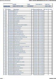
2. SELECTING THE INSTALLATION SITE<br />
Ceiling-Mounted Type<br />
Ceiling<br />
2-1. Indoor Unit<br />
AVOID:<br />
● areas where leakage of flammable gas may be<br />
expected.<br />
● places where large amounts of oil mist exist.<br />
● direct sunlight.<br />
● locations near heat sources which may affect the<br />
per<strong>for</strong>mance of the unit.<br />
● locations where external air may enter the room<br />
directly. This may cause “sweating” on the air discharge<br />
ports, causing them to spray or drip.<br />
● locations where the remote controller will be splashed<br />
with water or affected by dampness or humidity.<br />
● installing the remote controller behind curtains or furniture.<br />
● locations where high-frequency emissions are generated.<br />
DO:<br />
● select an appropriate position from which every corner<br />
of the room can be uni<strong>for</strong>mly cooled.<br />
● select a location where the ceiling is strong enough<br />
to support the weight of the unit.<br />
● select a location where tubing and drain pipe have<br />
the shortest run to the outdoor unit.<br />
● allow room <strong>for</strong> operation and maintenance as well as<br />
unrestricted air flow around the unit.<br />
● install the unit within the maximum elevation difference<br />
above or below the outdoor unit and within a<br />
total tubing length (L) from the outdoor unit as<br />
detailed in Table 1-19.<br />
● allow room <strong>for</strong> mounting the remote controller about<br />
1m off the floor, in an area that is not in direct sunlight<br />
nor in the flow of cool air from the indoor unit.<br />
min. 25 cm<br />
NOTE<br />
Concealed-Duct Type<br />
2-Way, 4-Way Semi-Concealed Type<br />
1 m<br />
Side view<br />
1 m 1 m<br />
min. 25 cm<br />
The rear of the indoor unit can be installed flush<br />
against the wall.<br />
Air<br />
discharge<br />
min. 1 m<br />
Front view<br />
min. 50 cm<br />
Fig. 2-1<br />
Fig. 2-2<br />
Air intake<br />
Max. 25 cm<br />
Obstacle<br />
1 m<br />
1 m<br />
Wall<br />
1-Way Semi-Concealed & Slim Type<br />
Semi-Concealed Type<br />
Obstacle<br />
Ceiling<br />
min. 5 cm<br />
Wall<br />
Semi-Concealed Slim Type<br />
100 cm<br />
20 cm<br />
NOTE<br />
Air delivery will be degraded if the distance from the<br />
floor to the ceiling is greater than 3 m (<strong>for</strong> ASBS type,<br />
greater than 3.5 m).<br />
Floor-Standing, Concealed Floor-Standing Type<br />
Air<br />
discharge<br />
Air<br />
intake<br />
min. 5 cm<br />
Side view<br />
Wall<br />
Fig. 2-3<br />
20 cm<br />
100<br />
cm<br />
20 cm<br />
min.<br />
10 cm<br />
min.<br />
10 cm<br />
min. 100 cm<br />
Wall-Mounted Type<br />
min. 100 cm<br />
min.<br />
15 cm<br />
min.15 cm<br />
min.<br />
15 cm<br />
Horizontal view<br />
Fig. 2-4<br />
Vertical view<br />
21<br />
Front View<br />
Fig. 2-5
<strong>06</strong>-<strong>06</strong>5 <strong>Mini</strong> <strong>ECO</strong>-i <strong>II</strong> <strong>for</strong> <strong>ARGO</strong> 2/8/<strong>06</strong> 4:37 PM Page 22<br />
2-2. Outdoor Unit<br />
AVOID:<br />
● heat sources, exhaust fans, etc. (Fig. 2-6)<br />
● damp, humid or uneven locations<br />
DO:<br />
● choose a place as cool as possible.<br />
● choose a place that is well ventilated and outside<br />
air temperature does not exceed maximum 45°C<br />
constantly.<br />
● allow enough room around the unit <strong>for</strong> air intake/<br />
exhaust and possible maintenance. (Fig. 2-7)<br />
● use lug bolts or equal to bolt down unit, reducing<br />
vibration and noise.<br />
Installation space<br />
Distance between obstructions and the unit air inlet<br />
and outlet must be as shown below.<br />
Hot air<br />
Outdoor<br />
unit<br />
Fig. 2-6<br />
Exhaust fan<br />
Heat source<br />
(Obstruction above unit)<br />
More than 1 cm<br />
*2<br />
*3<br />
Inlet side C<br />
Outlet side<br />
More than<br />
100 cm<br />
*1<br />
More than 1 cm<br />
*4<br />
Air direction chamber<br />
(field supply)<br />
*1<br />
A<br />
B<br />
Inlet side<br />
More than 20 cm<br />
(Obstruction on<br />
inlet side)<br />
Fig. 2-7<br />
(Ground)<br />
Fig. 2-8<br />
CAUTION<br />
● Concerning inlet-side distance “C” (Fig. 2-7)<br />
The minimum <strong>for</strong> distance “C” is 15 cm if there are no obstructions on the outlet side<br />
(wall *1 side) and *2 or *4 is not present. In all other cases, the minimum <strong>for</strong> distance<br />
“C” is 20 cm.<br />
● If the unit is installed with the outlet side facing wall *1, then there must be no obstructions<br />
on 2 of the remaining 3 sides: *2, *3, *4.<br />
● If wall *1 is on the outlet side (Fig. 2-7), or if obstructions are present on all 3 sides *2,<br />
*3, and *4 (Fig. 2-7), then the minimum distance <strong>for</strong> “A” and “B” is 2 m (Fig. 2-9). Even<br />
if there is no wall on the outlet side, a minimum of 100 cm is required.<br />
In case of multiple installations<br />
● provide a solid base (concrete block, 10 × 40 cm<br />
beams or equal), a minimum of 15 cm above<br />
ground level to reduce humidity and protect the unit<br />
against possible water damage and decreased service<br />
life. (Fig. 2-9)<br />
● use lug bolts or equal to bolt down unit, reducing<br />
vibration and noise.<br />
Anchor bolts<br />
(4 pieces)<br />
Fig. 2-9<br />
22
<strong>06</strong>-<strong>06</strong>5 <strong>Mini</strong> <strong>ECO</strong>-i <strong>II</strong> <strong>for</strong> <strong>ARGO</strong> 2/8/<strong>06</strong> 4:37 PM Page 23<br />
2-3. Air Discharge Chamber <strong>for</strong> Top Discharge<br />
Be sure to install an air discharge chamber in the<br />
field when:<br />
● it is difficult to keep a space of min. 50 cm between<br />
the air discharge outlet and an obstacle.<br />
Air discharge<br />
● the air discharge outlet is facing a sidewalk and<br />
discharged hot air may annoy passers-by.<br />
Refer to Fig. 2-10.<br />
2-4. Installing the Unit in Heavy Snow Areas<br />
In locations with strong wind, snow-proof ducting<br />
should be fitted and direct exposure to the wind<br />
should be avoided as much as possible.<br />
■ Countermeasures against snow and wind<br />
In regions with snow and strong wind, the following<br />
problems may occur when the outdoor unit is not provided<br />
with a plat<strong>for</strong>m and snow-proof ducting:<br />
a) The outdoor fan may not run and damage to the<br />
unit may occur.<br />
b) There may be no air flow.<br />
c) The tubing may freeze and burst.<br />
d) The condenser pressure may drop because of<br />
strong wind, and the indoor unit may freeze.<br />
2-5. Precautions <strong>for</strong> Installation in Heavy Snow<br />
Areas<br />
(1) The plat<strong>for</strong>m should be higher than the max. snow<br />
depth. (Fig. 2-11)<br />
(2) The 2 anchoring feet of the outdoor unit should be<br />
used <strong>for</strong> the plat<strong>for</strong>m, and the plat<strong>for</strong>m should be<br />
installed beneath the air intake side of outdoor<br />
unit.<br />
(3) The plat<strong>for</strong>m foundation must be firm and the unit<br />
must be secured with anchor bolts.<br />
(4) In case of installation on a roof subject to strong<br />
wind, countermeasures must be taken to prevent<br />
the unit from being blown over.<br />
Fig. 2-10<br />
In regions with significant snowfall, the outdoor unit should<br />
be provided with a plat<strong>for</strong>m and snow-proof duct.<br />
Without snowproof<br />
ducting<br />
(Low plat<strong>for</strong>m)<br />
Outdoor<br />
Unit<br />
Fig. 2-11<br />
With snowproof<br />
ducting<br />
(High plat<strong>for</strong>m)<br />
Duct<br />
Air<br />
Intake<br />
Fig. 2-12<br />
23
<strong>06</strong>-<strong>06</strong>5 <strong>Mini</strong> <strong>ECO</strong>-i <strong>II</strong> <strong>for</strong> <strong>ARGO</strong> 2/8/<strong>06</strong> 4:37 PM Page 24<br />
2-6. Dimensions of Air-Discharge Chamber<br />
Reference diagram <strong>for</strong> air-discharge chamber (field supply)<br />
For AES04/05/<strong>06</strong>MMIH<br />
1 Unit front, air discharge chamber<br />
2 Unit left side, air discharge chamber<br />
3 Unit light side, air discharge chamber<br />
4 Rein<strong>for</strong>cement brackets, 4 locations<br />
2<br />
300<br />
29.5<br />
240<br />
1 4<br />
3<br />
240<br />
29.5<br />
537<br />
35<br />
35<br />
Rectangular<br />
hole<br />
Rectangular<br />
hole<br />
317<br />
250<br />
250<br />
Rectangular<br />
hole<br />
317 70<br />
310<br />
997<br />
1090<br />
Rectangular<br />
hole<br />
250<br />
537 70<br />
569<br />
25 544<br />
25<br />
Unit: mm<br />
2-7. Dimensions of Outdoor Unit with Air-Discharge Chamber (field supply)<br />
For AES04/05/<strong>06</strong>MMIH<br />
340<br />
Wind<br />
direction<br />
170<br />
660<br />
Wind direction<br />
13 13<br />
110<br />
20<br />
380 10<br />
405<br />
13<br />
300<br />
20<br />
15<br />
300<br />
68 544<br />
108<br />
Wind direction<br />
940<br />
Wind direction<br />
Wind<br />
direction<br />
Wind<br />
direction<br />
997<br />
18<br />
1230<br />
Wind<br />
direction<br />
Wind<br />
direction<br />
Unit: mm<br />
24
<strong>06</strong>-<strong>06</strong>5 <strong>Mini</strong> <strong>ECO</strong>-i <strong>II</strong> <strong>for</strong> <strong>ARGO</strong> 2/8/<strong>06</strong> 4:37 PM Page 25<br />
Reference <strong>for</strong> air-discharge chamber (field supply)<br />
Required space around outdoor unit<br />
For Required AES04/05/<strong>06</strong>MMIH space around outdoor unit<br />
If an air discharge chamber is used, the space shown below must be secured around the outdoor unit.<br />
If the unit is used without the required space, a protective device may activate, preventing the unit from operating.<br />
(1) Single-unit installation<br />
Min. 1000<br />
Min. 200<br />
Unit: mm<br />
CAUTION<br />
The top and both sides must remain open.<br />
If there are obstacles to the front and rear of the outdoor unit,<br />
the obstacle at either the front or rear must be no taller than the<br />
height of the outdoor unit.<br />
(2) Multiple-unit installation<br />
● Installation in lateral rows<br />
More than 300<br />
More than 300<br />
More than 400<br />
More than 200<br />
Unit: mm<br />
CAUTION<br />
The front and top must remain open.<br />
The obstacles must be no taller than the height of the outdoor unit.<br />
● Installation in front-rear rows<br />
Installation with intakes facing<br />
intakes or outlets facing outlets<br />
Installation with intakes facing outlets<br />
More than 400<br />
More than 1500<br />
More than 2000<br />
CAUTION<br />
The front and both sides must remain open.<br />
Unit: mm<br />
25
<strong>06</strong>-<strong>06</strong>5 <strong>Mini</strong> <strong>ECO</strong>-i <strong>II</strong> <strong>for</strong> <strong>ARGO</strong> 2/8/<strong>06</strong> 4:37 PM Page 26<br />
2-8. Dimensions of Snow Ducting<br />
Reference diagram <strong>for</strong> snow-proof vents (field supply)<br />
For AES04/05/<strong>06</strong>MMIH<br />
Fastened by screws at 13 locations<br />
764<br />
1 Unit top, snow-proof vent<br />
2 Unit left side<br />
3 Unit right side<br />
4<br />
4 Unit reverse side<br />
5 Unit reverse side<br />
6 Unit sides, rein<strong>for</strong>cement brackets <strong>for</strong> snow-proof vent<br />
1<br />
Unit: mm<br />
645<br />
3 302<br />
444<br />
95 500<br />
101<br />
2<br />
1209<br />
500<br />
1209<br />
732<br />
450<br />
732<br />
233<br />
150<br />
20<br />
338<br />
233<br />
Fastened by screws at<br />
3 locations (also on reverse side)<br />
500<br />
Unit anchor hole<br />
(7 – ø 7 hole)<br />
16<br />
Fastened by screw at<br />
1 location (also on reverse side)<br />
388<br />
41 730<br />
778<br />
46<br />
2-9. Dimensions of Outdoor Unit with Snow-Proof Vents (field supply)<br />
For AES04/05/<strong>06</strong>MMIH<br />
764<br />
179<br />
Wind direction Wind direction<br />
Wind direction<br />
Wind direction<br />
632<br />
940<br />
302<br />
Wind direction<br />
1230<br />
1209<br />
645<br />
732<br />
20<br />
380 10<br />
405<br />
20<br />
15<br />
Unit: mm<br />
Wind direction<br />
26
<strong>06</strong>-<strong>06</strong>5 <strong>Mini</strong> <strong>ECO</strong>-i <strong>II</strong> <strong>for</strong> <strong>ARGO</strong> 2/8/<strong>06</strong> 4:37 PM Page 27<br />
Reference diagram <strong>for</strong> snow-proof vents – 1<br />
Space requirements <strong>for</strong> setting – (1)<br />
AES04/05/<strong>06</strong>MMIH<br />
[Obstacle to the rear of unit]<br />
[Obstacle to the front of unit]<br />
●• Top is open:<br />
(1) Single-unit installation<br />
(2) Obstacles on both sides<br />
●• Top is open:<br />
(1) Single-unit installation<br />
Min. A<br />
Min. D<br />
Min. H<br />
Min. B<br />
Min. C<br />
(2) Multiple-unit installation (2 or more units)<br />
(3) Multiple-unit installation (2 or more units)<br />
Min. I<br />
Min. I<br />
Min. J<br />
Min. G<br />
Outdoor unit<br />
H I J<br />
Min. E<br />
Min. E<br />
Min. E<br />
AES04/05/<strong>06</strong>MMIH<br />
500 300 1000<br />
Min. F<br />
Outdoor unit<br />
AES04/05/<strong>06</strong>MMIH<br />
A B C D E F G<br />
150 150<br />
300 200 300 150 200<br />
●• Top is blocked by an obstacle:<br />
Min. M<br />
Min. N<br />
Min. L<br />
Min. K<br />
Note: In cases 2 and 3 the height of the obstacle<br />
must be no taller than the height of the outdoor<br />
unit.<br />
●• Top is blocked by an obstacle:<br />
Outdoor unit K L<br />
AES04/05/<strong>06</strong>MMIH 500 150<br />
Outdoor unit M N<br />
AES04/05/<strong>06</strong>MMIH 1000 1000<br />
Unit: mm<br />
27
<strong>06</strong>-<strong>06</strong>5 <strong>Mini</strong> <strong>ECO</strong>-i <strong>II</strong> <strong>for</strong> <strong>ARGO</strong> 2/8/<strong>06</strong> 4:37 PM Page 28<br />
Reference diagram <strong>for</strong> snow-proof vents – 2<br />
Space requirements <strong>for</strong> setting – (2)<br />
AES04/05/<strong>06</strong>MMIH<br />
[Obstacles to the front and rear of unit]<br />
●• The top and both sides must remain open. Either the obstacle to the front or<br />
the obstacle to the rear must be no taller than the height of the outdoor unit.<br />
(1) Single-unit installation<br />
Min. O<br />
Min. P<br />
Q<br />
Dimension Q<br />
If a snow protection duct is attached after the unit is<br />
installed, verify that dimension Q is 500 mm or more.<br />
Outdoor unit<br />
AES04/05/<strong>06</strong>MMIH<br />
O P<br />
1000 150<br />
(2) Obstacles on both sides<br />
Min. 300<br />
Min. 300<br />
Min. 1000<br />
Min. 200<br />
Q<br />
[Installation in front-rear rows]<br />
●• The top and both sides must remain open. Either the obstacle to the front or the obstacle<br />
to the rear must be no taller than the height of the outdoor unit.<br />
Min. 300<br />
0<br />
Min. 1000 Min. 1500 Min. 2000<br />
Min. 200<br />
Dimension Q<br />
If a snow protection duct is<br />
attached after the unit is<br />
installed, verify that dimension<br />
Q is 500 mm or more.<br />
Unit: mm<br />
28
<strong>06</strong>-<strong>06</strong>5 <strong>Mini</strong> <strong>ECO</strong>-i <strong>II</strong> <strong>for</strong> <strong>ARGO</strong> 2/8/<strong>06</strong> 4:37 PM Page 29<br />
3. HOW TO INSTALL THE INDOOR UNIT<br />
■ 1-Way Air Discharge Semi-Concealed Type<br />
(AS1S Type)<br />
3-1. Suspending the Indoor Unit<br />
(1) Follow the diagrams to make the holes in the ceiling.<br />
(Figs. 3-1 and 3-2)<br />
(2) Depending on the ceiling type:<br />
● Insert suspension bolts as shown in Fig. 3-3<br />
or<br />
● Use existing ceiling supports or construct a suitable<br />
support as shown in Fig. 3-4.<br />
WARNING<br />
It is important that you use<br />
extreme care in supporting<br />
the indoor unit from the ceiling.<br />
Ensure that the ceiling<br />
is strong enough to support<br />
the weight of the unit.<br />
Be<strong>for</strong>e hanging the unit, test<br />
the strength of each<br />
attached suspension bolt.<br />
20 20<br />
287<br />
15<br />
20<br />
780 (Ceiling opening dimension)<br />
652 (Suspension bolt pitch)<br />
74<br />
268<br />
560<br />
Fig. 3-1<br />
74<br />
Drain outlet<br />
15<br />
483<br />
(Suspension bolt pitch)<br />
590<br />
(Ceiling opening dimension)<br />
4 – 12 × 37 oblong holes<br />
Suspension lug<br />
65<br />
Unit: mm<br />
Unit: mm<br />
Power wiring outlet<br />
AS1S<br />
(3) Cut the ceiling material, if necessary.<br />
(Figs. 3-1 and 3-2)<br />
60<br />
115 40 100<br />
30<br />
Drain inspection port<br />
Flared refrigerant connection outlet (liquid tube)<br />
Flared refrigerant connection outlet (gas tube)<br />
Fig. 3-2<br />
Hole-in-anchor<br />
Hole-in-plug Concrete Insert<br />
Suspension bolt (M10 or 3/8")<br />
(field supply)<br />
Fig. 3-3<br />
Ceiling tiles<br />
Ceiling support<br />
Fig. 3-4<br />
29
<strong>06</strong>-<strong>06</strong>5 <strong>Mini</strong> <strong>ECO</strong>-i <strong>II</strong> <strong>for</strong> <strong>ARGO</strong> 2/8/<strong>06</strong> 4:37 PM Page 30<br />
If the system requires fresh air to be drawn into the unit,<br />
cut and remove the insulation (both externally and internally)<br />
at the location shown as A in Fig. 3-5.<br />
177<br />
Unit: mm<br />
AS1S<br />
CAUTION<br />
When making the cuts to<br />
the insulation, be careful<br />
not to damage the drain<br />
pan.<br />
140<br />
3-2. Placing the<br />
Unit Inside the Ceiling<br />
Fig. 3-5<br />
For fresh air intake<br />
(ø125 hole) A<br />
(1) When placing the unit inside the ceiling, determine<br />
the pitch of the suspension bolts.<br />
Tubing must be laid and connected inside the ceiling<br />
when suspending the unit. If the ceiling is<br />
already constructed, lay the tubing into position <strong>for</strong><br />
connection to the unit be<strong>for</strong>e placing the unit<br />
inside the ceiling.<br />
Nuts and washers<br />
Upper<br />
Suspension bolt<br />
Suspension lug<br />
(2) Thread the 3 hexagonal nuts and 2 washers (field<br />
supply) onto each of the the 4 suspension bolts as<br />
shown in Fig. 3-6. Use 1 nut and 1 washer <strong>for</strong> the<br />
upper side, and 2 nuts and 1 washer <strong>for</strong> the lower<br />
side, so that the unit will not fall off the suspension<br />
lugs.<br />
Double nuts<br />
Lower<br />
Fig. 3-6<br />
(3) The distance between the unit and the opening of<br />
the ceiling and the distance between the bottom<br />
surface of the ceiling and the bottom surface of the<br />
flange of the unit should follow the dimensions<br />
given in Figs. 3-7 and 3-8.<br />
20<br />
74 74<br />
Suspension bolts<br />
Tubing side<br />
20<br />
Suspension bolts<br />
Fig. 3-7<br />
Unit: mm<br />
Ceiling<br />
material<br />
37<br />
5<br />
Unit: mm<br />
Fig. 3-8<br />
30
<strong>06</strong>-<strong>06</strong>5 <strong>Mini</strong> <strong>ECO</strong>-i <strong>II</strong> <strong>for</strong> <strong>ARGO</strong> 2/8/<strong>06</strong> 4:37 PM Page 31<br />
(4) Adjust the distance between the unit and the<br />
opening in the ceiling to give clearances of 15 mm<br />
in the front and back directions and 70 mm in the<br />
right and left directions so that the height between<br />
the bottom surface of the flange of the unit and the<br />
bottom surface of the ceiling is 37 mm, and the airintake<br />
side is 5 mm. To check these dimensions<br />
<strong>for</strong> positioning the unit, use the installation gauge<br />
which is taped on the unit. (Fig. 3-9)<br />
70<br />
5<br />
37<br />
15<br />
Unit: mm<br />
AS1S<br />
(5) Confirm all clearances with the installation gauge<br />
as follows:<br />
Installation gauge<br />
● Between each side of the unit and the opening of<br />
the ceiling:<br />
15 mm<br />
70 mm<br />
Fig. 3-9<br />
● Between bottom of unit flange and ceiling material:<br />
5 mm (2 corners)<br />
37 mm (2 corners)<br />
Improper clearance can lead to poor mounting of the<br />
ceiling panel, causing condensation and dripping.<br />
(Fig. 3-9)<br />
3-3. Installing the Drain Piping<br />
(1) Prepare standard hard PVC pipe (O.D. 32 mm) <strong>for</strong><br />
the drain and use the supplied drain hose and<br />
hose band to prevent water leaks.<br />
The PVC pipe must be purchased separately. The<br />
unit’s transparent drain port allows you to check<br />
drainage. (Fig. 3-10)<br />
CAUTION<br />
Align the hose band with end of the<br />
hose, and tighten so that it does not<br />
contact the bead.<br />
Drainage check<br />
section on drain port<br />
(transparent)<br />
Drain hose<br />
(supplied)<br />
Hard PVC<br />
socket VP-25<br />
(not supplied)<br />
Hard PVC<br />
pipe<br />
VP-25<br />
(not supplied)<br />
● Do not use adhesive at the drain connection<br />
port on the indoor unit.<br />
● Insert the drain pipe until it contacts the socket,<br />
as shown in the figure at right, then secure it<br />
tightly with the hose band.<br />
● Tighten the hose clamps so their locking nuts<br />
face upward. (Fig. 3-10)<br />
● Do not use the supplied drain hose bent at a 90°<br />
angle. (The maximum permissible bend is 45°.)<br />
PVC adhesive<br />
Bead Packing (supplied)<br />
Fig. 3-10<br />
Drain insulator (supplied)<br />
(2) After checking the drainage, wrap the supplied<br />
packing and drain pipe insulator around the pipe,<br />
then secure it with the supplied clamps. (Fig. 3-11)<br />
NOTE<br />
Make sure the drain pipe has a downward gradient<br />
(1/100 or more) and that there are no water traps.<br />
Vinyl clamps<br />
Fig. 3-11<br />
31
<strong>06</strong>-<strong>06</strong>5 <strong>Mini</strong> <strong>ECO</strong>-i <strong>II</strong> <strong>for</strong> <strong>ARGO</strong> 2/8/<strong>06</strong> 4:37 PM Page 32<br />
CAUTION<br />
AS1S<br />
● Do not install an air bleeder as this may cause<br />
water to spray from the drain pipe outlet.<br />
(Fig. 3-12)<br />
● If it is necessary to increase the height of the<br />
drain pipe, the section directly after the connection<br />
port can be raised a maximum of 50<br />
cm. Do not raise it any higher than 50 cm, as<br />
this could result in water leaks. (Fig. 3-13)<br />
● Do not install the pipe with an upward gradient<br />
from the connection port. This will cause the<br />
drain water to flow backward and leak when the<br />
unit is not operating. (Fig. 3-14)<br />
● Do not apply <strong>for</strong>ce to the piping on the unit side<br />
when connecting the drain pipe. The pipe<br />
should not be allowed to hang unsupported<br />
from its connection to the unit. Fasten the pipe<br />
to a wall, frame, or other support as close to<br />
the unit as possible. (Fig. 3-15)<br />
● Provide insulation <strong>for</strong> any pipes that are run<br />
indoors.<br />
Air bleeder<br />
Fig. 3-12<br />
30 cm or less (as short as possible)<br />
50 cm or less<br />
Fig. 3-13<br />
Upward gradient prohibited<br />
Fig. 3-14<br />
Support<br />
pieces<br />
Fig. 3-15<br />
32
<strong>06</strong>-<strong>06</strong>5 <strong>Mini</strong> <strong>ECO</strong>-i <strong>II</strong> <strong>for</strong> <strong>ARGO</strong> 2/8/<strong>06</strong> 4:37 PM Page 33<br />
3-4. Checking the Drainage<br />
After wiring and drain piping are completed, use the<br />
following procedure to check that the water will drain<br />
smoothly. For this, prepare a bucket and wiping cloth<br />
to catch and wipe up spilled water.<br />
Siphon pump<br />
AS1S<br />
(1) Connect power to the power terminal board (R, S<br />
terminals) inside the electrical component box.<br />
(2) Pour water into the drain pan about 500 cc using a<br />
siphon pump through the air outlet grille.<br />
(Fig. 3-16)<br />
(3) Short the check pin (CHK) on the indoor control<br />
board and operate the drain pump. Check the<br />
water flow through the transparent drain pipe and<br />
see if there is any leakage.<br />
Fig. 3-16<br />
Drain pan<br />
CAUTION<br />
Be careful since the fan will<br />
start when you short the<br />
pin on the indoor control<br />
board.<br />
(4) When the drainage check is complete, open the<br />
check pin (CHK) and remount the insulator.<br />
CAUTION<br />
The bottom drain port is <strong>for</strong><br />
use only during test runs<br />
and servicing inspections.<br />
Do not connect the drain<br />
pipe to the bottom drain<br />
port.<br />
33
<strong>06</strong>-<strong>06</strong>5 <strong>Mini</strong> <strong>ECO</strong>-i <strong>II</strong> <strong>for</strong> <strong>ARGO</strong> 2/8/<strong>06</strong> 4:37 PM Page 34<br />
■ 1-Way Air Discharge Semi-Concealed Slim<br />
Type (ASBS Type)<br />
Front face<br />
ASBS<br />
3-5. Suspending the Indoor Unit<br />
(1) Place the full-scale diagram (supplied) on the ceiling<br />
at the spot where you want to install the indoor<br />
unit. Use a pencil to mark the drill holes. Refer to<br />
Table 3-1 and Figs. 3-17 and 3-19.<br />
NOTE<br />
Since the diagram is made of paper, it may shrink or<br />
stretch due to high temperature or humidity. For this<br />
reason, be<strong>for</strong>e drilling the holes maintain the correct<br />
dimensions between the markings.<br />
(2) Follow the diagrams to make the holes in the ceiling.<br />
(Figs. 3-18 and 3-19)<br />
Table 3-1<br />
Type<br />
Length<br />
A<br />
B<br />
28, 36, 56 1,193 1,089<br />
73 1,390 1,286<br />
The distance between the<br />
bottom of the suspension<br />
bolts and the bottom surface<br />
of the ceiling should be 30 to<br />
100 mm. (Fig. 3-24)<br />
88 35<br />
Unit: mm<br />
52<br />
690(Ceiling<br />
opening dimension)<br />
221 40<br />
Refrigerant tubing joint<br />
(liquid tube side)<br />
Rear<br />
Full-scale diagram<br />
Fig. 3-17<br />
A (Ceiling opening dimension)<br />
52 B (Suspension bolt pitch)<br />
(52)<br />
197 405<br />
(Suspension bolt pitch)<br />
Refrigerant tubing joint<br />
(gas tube side)<br />
Air discharge side<br />
Fig. 3-18<br />
Suspension lug<br />
18<br />
Drain hose<br />
Refrigerant tube<br />
39<br />
157 28<br />
Drain<br />
connection port<br />
140<br />
Unit: mm<br />
40<br />
192<br />
221<br />
Unit: mm<br />
157<br />
198<br />
15<br />
(3) Depending on the ceiling type:<br />
Air-discharge side<br />
● Insert suspension bolts as shown in Fig. 3-20.<br />
or<br />
● Use existing ceiling supports or construct a suitable<br />
support as shown in Fig. 3-21.<br />
Fig. 3-19<br />
Hole-in-anchor<br />
Hole-in-plug Concrete Insert<br />
WARNING<br />
It is important that you<br />
use extreme care in supporting<br />
the indoor unit<br />
from the ceiling. Ensure<br />
that the ceiling is strong<br />
enough to support the<br />
weight of the unit. Be<strong>for</strong>e<br />
hanging the unit, test the<br />
strength of each attached<br />
suspension bolt.<br />
Suspension bolt (M10 or 3/8")<br />
(field supply)<br />
Fig. 3-20<br />
Ceiling tiles<br />
Ceiling support<br />
(4) Cut the ceiling material, if necessary.<br />
(Figs. 3-18 and 3-19)<br />
Fig. 3-21<br />
34
<strong>06</strong>-<strong>06</strong>5 <strong>Mini</strong> <strong>ECO</strong>-i <strong>II</strong> <strong>for</strong> <strong>ARGO</strong> 2/8/<strong>06</strong> 4:37 PM Page 35<br />
(5) If the system requires fresh air to be drawn into<br />
the unit, cut and remove the insulation (both externally<br />
and internally) at the location shown as A<br />
in Fig. 3-22.<br />
3-6. Placing the Unit Inside the Ceiling<br />
(1) When placing the unit inside the ceiling, determine<br />
the pitch of the suspension bolts using the supplied<br />
full-scale installation diagram. (Fig. 3-17)<br />
Tubing must be laid and connected inside the ceiling<br />
when suspending the unit. If the ceiling is<br />
already constructed, lay the tubing into position <strong>for</strong><br />
connection to the unit be<strong>for</strong>e placing the unit<br />
inside the ceiling.<br />
125<br />
Nuts and washers<br />
635<br />
Fig. 3-22<br />
Fresh air intake<br />
knock-out hole<br />
ø125<br />
Suspension bolt<br />
88<br />
Suspension lug<br />
Unit: mm<br />
88<br />
Power supply<br />
inlet<br />
ASBS<br />
(2) Thread the 3 hexagonal nuts and 2 washers (field<br />
supply) onto each of the the 4 suspension bolts as<br />
shown in Fig. 3-23. Use 1 nut and 1 washer <strong>for</strong> the<br />
upper side, and 2 nuts and 1 washer <strong>for</strong> the lower<br />
side, so that the unit will not fall off the suspension<br />
lugs.<br />
Double nuts<br />
Upper<br />
Lower<br />
(3) The indoor unit should be suspended from the<br />
suspension bolts (Fig. 3-23) so that the distance<br />
between the bottom of the suspension lug and the<br />
bottom surface of the ceiling is 30 to 40 mm.<br />
(Fig. 3-24)<br />
Clearance between the indoor unit and the bottom<br />
surface of the ceiling is adjustable after the ceiling<br />
panel is attached to the unit.<br />
(4) The unit should be adjusted using water level or<br />
as shown in Fig. 3-25 so that the drain pipe side is<br />
slanted 5 mm lower than the opposite side.<br />
(5) After completing the adjustment of the clearance,<br />
fasten all upper and lower suspension nuts tightly.<br />
Suspension<br />
lug<br />
30 to 40 mm<br />
Fig. 3-23<br />
Full-scale<br />
installation diagram<br />
Fig. 3-24<br />
30 to 40 mm<br />
Drain pipe side<br />
Poured<br />
water<br />
0 to 5 mm<br />
Vinyl hose<br />
Fig. 3-25<br />
35
<strong>06</strong>-<strong>06</strong>5 <strong>Mini</strong> <strong>ECO</strong>-i <strong>II</strong> <strong>for</strong> <strong>ARGO</strong> 2/8/<strong>06</strong> 4:37 PM Page 36<br />
3-7. Installing the Drain Piping<br />
ASBS<br />
(1) Prepare standard hard PVC pipe (O.D. 32 mm) <strong>for</strong><br />
the drain and use the supplied drain hose and hose<br />
band to prevent water leaks. The PVC pipe must be<br />
purchased separately. The unit’s transparent drain<br />
port allows you to check drainage. (Fig. 3-26a)<br />
CAUTION<br />
Align the hose band with end of the<br />
hose, and tighten so that it does not<br />
contact the bead.<br />
Drainage check<br />
section on drain port<br />
(transparent)<br />
Drain hose<br />
(supplied)<br />
Hard PVC<br />
socket VP-25<br />
(not supplied)<br />
Hard PVC<br />
pipe<br />
VP-25<br />
(not supplied)<br />
● Do not use adhesive at the drain connection<br />
port on the indoor unit.<br />
● Insert the drain pipe until it contacts the socket,<br />
as shown in the figure at right, then secure<br />
it tightly with the hose band.<br />
● Tighten the hose clamps so their locking nuts<br />
face upward. (Fig. 3-26a)<br />
● Do not use the supplied drain hose bent at a 90°<br />
angle. (The maximum permissible bend is 45°.)<br />
PVC adhesive<br />
Bead Packing (supplied)<br />
Fig. 3-26a<br />
Drain insulator (supplied)<br />
(2) After checking the drainage, wrap the supplied<br />
packing and drain pipe insulator around the pipe,<br />
then secure it with the supplied clamps. (Fig. 3-26b)<br />
NOTE<br />
Make sure the drain pipe has a downward gradient<br />
(1/100 or more) and that there are no water traps.<br />
Vinyl clamps<br />
Fig. 3-26b<br />
36
<strong>06</strong>-<strong>06</strong>5 <strong>Mini</strong> <strong>ECO</strong>-i <strong>II</strong> <strong>for</strong> <strong>ARGO</strong> 2/8/<strong>06</strong> 4:37 PM Page 37<br />
CAUTION<br />
Air bleeder prohibited<br />
● Do not install an air bleeder as this may cause<br />
water to spray from the drain pipe outlet.<br />
(Fig. 3-27)<br />
● If it is necessary to increase the height of the drain<br />
pipe, the pipe can be raised a maximum of 59 cm<br />
from the bottom of the ceiling. Do not raise it any<br />
higher than 59 cm, as this could result in water<br />
leaks. (Fig. 3-28)<br />
● Do not install the pipe with an upward gradient from<br />
the connection port. This will cause the drain water<br />
to flow backward and leak when the unit is not<br />
operating. (Fig. 3-29)<br />
● Do not apply <strong>for</strong>ce to the piping on the unit side<br />
when connecting the drain pipe. The pipe should<br />
not be allowed to hang unsupported from its connection<br />
to the unit. Fasten the pipe to a wall, frame,<br />
or other support as close to the unit as possible.<br />
(Fig. 3-30)<br />
● Provide insulation <strong>for</strong> any pipes that are run<br />
indoors.<br />
3-8. Checking the Drainage<br />
After wiring and drain piping are completed, use the<br />
following procedure to check that the water will drain<br />
smoothly. For this, prepare a bucket and wiping cloth<br />
to catch and wipe up spilled water.<br />
(1) Connect power to the power terminal board (R, S<br />
terminals) inside the electrical component box.<br />
(2) Short the check pin (CHK) on the indoor control<br />
board and operate the drain pump.<br />
Siphon pump<br />
Fig. 3-27<br />
Fig. 3-28<br />
Fig. 3-29<br />
Fig. 3-30<br />
Fig. 3-31<br />
30 cm or less<br />
(as short as possible)<br />
59 cm or less<br />
Upward gradient prohibited<br />
Support<br />
pieces<br />
ASBS<br />
CAUTION<br />
Be careful since the fan will<br />
start when you short the<br />
pin on the indoor control<br />
board.<br />
(3) Pour water into the drain pan using a siphon pump<br />
through the air outlet grille. (Fig. 3-31) Check the<br />
water flow through the transparent drain pipe and<br />
see if there is any leakage.<br />
37
<strong>06</strong>-<strong>06</strong>5 <strong>Mini</strong> <strong>ECO</strong>-i <strong>II</strong> <strong>for</strong> <strong>ARGO</strong> 2/8/<strong>06</strong> 4:37 PM Page 38<br />
(4) When the check of drainage is complete, open the<br />
check pin (CHK) and remount the insulator.<br />
ASBS<br />
CAUTION<br />
Use 4 × 8 tapping screws to<br />
fasten cover drainage. If the<br />
screws used are longer<br />
than 8 mm, it may make a<br />
hole in the drain pan and<br />
cause leakage.<br />
Drain pump installation screw<br />
Cleaning the sub drain pan<br />
Be<strong>for</strong>e beginning work, make necessary preparations<br />
(e.g., prepare a bucket, wiping cloth, etc.).<br />
(1) Unscrew the 2 screws securing the cover, and<br />
place them on the reverse side to remove the<br />
cover.<br />
(2) Release the screw securing the sub drain pan<br />
support L-shape bracket, and remove the bracket<br />
while holding the sub drain pan with your hand.<br />
Drain pump<br />
Drain hose<br />
Sub drain pan<br />
CAUTION<br />
Continuing to work without<br />
holding the sub drain pan<br />
causes accumulated water<br />
in the sub drain pan to leak<br />
out.<br />
Fig. 3-32<br />
(3) Drain any water and clean the sub drain pan by<br />
tilting it downward. To remove the drain pump,<br />
remove the 4 drain pump installation screws, the<br />
drain hose, and the wiring.<br />
Removing the side panel<br />
(1) Push the tab on both sides of the side panel<br />
inward (a) to disengage the tab (first stage) and<br />
move the panel horizontally (b).<br />
(2) Push the area in the vicinity of the tab (second<br />
stage) inward while holding both sides of the side<br />
panel to remove the side panel.<br />
Tab (second stage)<br />
Tab (first stage)<br />
Tab of both sides<br />
Fig. 3-33<br />
b<br />
a<br />
Side panel<br />
38
<strong>06</strong>-<strong>06</strong>5 <strong>Mini</strong> <strong>ECO</strong>-i <strong>II</strong> <strong>for</strong> <strong>ARGO</strong> 2/8/<strong>06</strong> 4:37 PM Page 39<br />
■ 2-Way Air Discharge Semi-Concealed Type<br />
(AS2S Type)<br />
3-9. Suspending the Indoor Unit<br />
(1) Follow the diagrams to make the holes in the ceiling.<br />
Table 3-2<br />
Unit: mm<br />
A B C D E<br />
22, 28, 36, 56 1,020 920 840 400 440<br />
73 1,320 1,220 1,140 550 590<br />
(2) Depending on the ceiling type:<br />
● Insert suspension bolts as shown in Fig. 3-36<br />
20 600<br />
40<br />
70<br />
D<br />
C<br />
Center of panel<br />
and ceiling<br />
opening<br />
E<br />
Suspension bolt pitch B<br />
Ceiling opening dimension A<br />
Fig. 3-34<br />
530<br />
30<br />
Suspension bolt pitch<br />
640<br />
Ceiling opening dimension<br />
Unit: mm<br />
AS2S<br />
or<br />
● Use existing ceiling supports or construct a suitable<br />
support as shown in Fig. 3-37.<br />
110<br />
600<br />
Unit: mm<br />
WARNING<br />
It is important that you use<br />
extreme care in supporting<br />
the indoor unit from the ceiling.<br />
Ensure that the ceiling<br />
is strong enough to support<br />
the weight of the unit.<br />
Be<strong>for</strong>e hanging the unit, test<br />
the strength of each<br />
attached suspension bolt.<br />
Drain outlet<br />
Refrigerant<br />
connection outlet<br />
(gas tube)<br />
30<br />
70<br />
220<br />
115<br />
195<br />
Refrigerant connection<br />
outlet (liquid tube)<br />
Outlet <strong>for</strong> power cord,<br />
inter-unit wiring &<br />
optional cord<br />
290<br />
60 – 65<br />
350<br />
8<br />
(3) Cut the ceiling material, if necessary. (Refer to<br />
Figs. 3-34 and 3-35, and Table 3-2.)<br />
Adjust so that the distance between the indoor unit<br />
and the ceiling bottom is 60 to 65 mm.<br />
Fig. 3-35<br />
Hole-in-anchor<br />
Hole-in-plug Concrete Insert<br />
Suspension bolt (M10 or 3/8")<br />
(field supply)<br />
Fig. 3-36<br />
Ceiling tiles<br />
Ceiling support<br />
Fig. 3-37<br />
39
<strong>06</strong>-<strong>06</strong>5 <strong>Mini</strong> <strong>ECO</strong>-i <strong>II</strong> <strong>for</strong> <strong>ARGO</strong> 2/8/<strong>06</strong> 4:37 PM Page 40<br />
AS2S<br />
(5) If the system requires fresh air to be drawn into<br />
the unit, cut and remove the insulation (both externally<br />
and internally) at the location shown as A<br />
in Fig. 3-38.<br />
CAUTION<br />
When making the cuts to the<br />
insulation, be careful not to<br />
damage the drain pan.<br />
3-10. Placing the Unit Inside the Ceiling<br />
(1) When placing the unit inside the ceiling, determine<br />
the pitch of the suspension bolts.<br />
Tubing must be laid and connected inside the ceiling<br />
when suspending the unit. If the ceiling is<br />
already constructed, lay the tubing into position <strong>for</strong><br />
connection to the unit be<strong>for</strong>e placing the unit<br />
inside the ceiling.<br />
(2) Thread the 3 hexagonal nuts and 2 washers (field<br />
supply) onto each of the the 4 suspension bolts as<br />
shown in Fig. 3-40. Use 1 nut and 1 washer <strong>for</strong> the<br />
upper side, and 2 nuts and 1 washer <strong>for</strong> the lower<br />
side, so that the unit will not fall off the suspension<br />
lugs.<br />
(3) The distance between the unit and the opening in<br />
the ceiling and the distance between the bottom<br />
surface of the ceiling and the bottom surface of the<br />
flange of the unit should follow the dimensions<br />
given in Figs. 3-39. Use the supplied installation<br />
gauge to check.<br />
3-11. Installing the Drain Piping<br />
(1) Prepare a standard hard PVC pipe (O.D. 32 mm)<br />
<strong>for</strong> the drain and use the supplied drain hose and<br />
hose band to prevent water leaks. The PVC pipe<br />
must be purchased separately.<br />
When doing this, leave a gap between the drain<br />
socket and the PVC pipe to allow the drainage to<br />
be checked. The unit’s transparent drain port<br />
allows you to check the drainage. (Fig. 3-41)<br />
Nuts and washers<br />
Double nuts<br />
ø150<br />
ø162<br />
ø138<br />
A<br />
Fig. 3-38<br />
Fig. 3-39<br />
Suspension bolt<br />
Suspension lug<br />
Upper<br />
Lower<br />
Fig. 3-40<br />
60<br />
Unit: mm<br />
CAUTION<br />
● Do not use adhesive at the drain connection port<br />
on the indoor unit.<br />
● Insert the drain pipe until it contacts the socket,<br />
as shown in the figure at right, then secure it<br />
tightly with the hose band.<br />
● Tighten the hose clamps so their locking nuts<br />
face upward. (Fig. 3-41)<br />
● Do not use the supplied drain hose bent at a 90°<br />
angle. (The maximum permissible bend is 45°.)<br />
Align the hose band with end of the<br />
hose, and tighten so that it does not<br />
contact the bead.<br />
Drainage check<br />
section on drain port<br />
(transparent)<br />
Bead<br />
Drain hose<br />
(supplied)<br />
Fig. 3-41<br />
Hard PVC<br />
socket VP-25<br />
(not supplied)<br />
Hard PVC<br />
pipe<br />
VP-25<br />
(not supplied)<br />
PVC adhesive<br />
Packing (supplied)<br />
40
<strong>06</strong>-<strong>06</strong>5 <strong>Mini</strong> <strong>ECO</strong>-i <strong>II</strong> <strong>for</strong> <strong>ARGO</strong> 2/8/<strong>06</strong> 4:37 PM Page 41<br />
(2) After checking the drainage, wrap the supplied<br />
packing and drain pipe insulator around the pipe,<br />
then secure it with the supplied clamps. (Fig. 3-42)<br />
Drain insulator (supplied)<br />
NOTE<br />
Make sure the drain pipe has a downward gradient<br />
(1/100 or more) and that there are no water traps.<br />
Vinyl clamps<br />
Fig. 3-42<br />
CAUTION<br />
● Do not install an air bleeder as this may cause<br />
water to spray from the drain pipe outlet.<br />
(Fig. 3-43)<br />
● If it is necessary to increase the height of the<br />
drain pipe, the section directly after the connection<br />
port can be raised a maximum of 50<br />
cm. Do not raise it any higher than 50 cm, as<br />
this could result in water leaks. (Fig. 3-44)<br />
● Do not install the pipe with an upward gradient<br />
from the connection port. This will cause the<br />
drain water to flow backward and leak when the<br />
unit is not operating. (Fig. 3-45)<br />
● Do not apply <strong>for</strong>ce to the piping on the unit side<br />
when connecting the drain pipe. The pipe<br />
should not be allowed to hang unsupported<br />
from its connection to the unit. Fasten the pipe<br />
to a wall, frame, or other support as close to<br />
the unit as possible. (Fig. 3-46)<br />
● Provide insulation <strong>for</strong> any pipes that are<br />
installed indoors.<br />
Air bleeder prohibited<br />
Fig. 3-43<br />
30 cm or less (as short as possible)<br />
50 cm or less<br />
Fig. 3-44<br />
Upward gradient prohibited<br />
AS2S<br />
Fig. 3-45<br />
Support<br />
pieces<br />
Fig. 3-46<br />
41
<strong>06</strong>-<strong>06</strong>5 <strong>Mini</strong> <strong>ECO</strong>-i <strong>II</strong> <strong>for</strong> <strong>ARGO</strong> 2/8/<strong>06</strong> 4:37 PM Page 42<br />
3-12. Checking the Drainage<br />
After wiring and drain piping are completed, use the<br />
following procedure to check that the water will drain<br />
smoothly. For this, prepare a bucket and wiping cloth<br />
to catch and wipe up spilled water.<br />
(1) Connect power to the power terminal board (R, S<br />
terminals) inside the electrical component box.<br />
(2) Remove the tube cover and through the opening,<br />
slowly pour about 1,200 cc of water into the drain<br />
pan to check the drainage.<br />
(3) Short the check pin (CHK) on the indoor control<br />
board and operate the drain pump. Check the<br />
water flow through the transparent drain port and<br />
see if there is any leakage.<br />
AS2S<br />
Drainage check section<br />
(transparent drain port)<br />
Inspection cover<br />
CAUTION<br />
Be careful since the fan will<br />
start when you short the<br />
pin on the indoor control<br />
board.<br />
(4) When the check of drainage is complete, open the<br />
check pin (CHK) and remount the tube cover.<br />
(Fig. 3-47)<br />
CAUTION<br />
To mount the tube cover,<br />
use 4 × 8 tapping screws.<br />
(Fig. 3-47)<br />
Do not use long screws as<br />
they may puncture the<br />
drain pan and cause water<br />
leakage.<br />
Fig. 3-47<br />
Water <strong>for</strong> checking drainage<br />
(Approx. 1,200 cc)<br />
42
<strong>06</strong>-<strong>06</strong>5 <strong>Mini</strong> <strong>ECO</strong>-i <strong>II</strong> <strong>for</strong> <strong>ARGO</strong> 2/8/<strong>06</strong> 4:37 PM Page 43<br />
■ 4-Way Air Discharge Semi-Concealed Type<br />
(ASS Type)<br />
3-13. Preparation <strong>for</strong> Suspending<br />
This unit uses a drain pump. Use a carpenter’s level<br />
to check that the unit is level.<br />
3-14. Suspending the Indoor Unit<br />
(1) Fix the suspension bolts securely in the ceiling<br />
using the method shown in the diagrams (Figs. 3-<br />
48 and 3-49), by attaching them to the ceiling support<br />
structure, or by any other method that<br />
ensures that the unit will be securely and safely<br />
suspended.<br />
(2) Follow Fig. 3-49 and Table 3-3 to make the holes<br />
in the ceiling.<br />
Table 3-3<br />
Unit: mm<br />
Length<br />
Type A B C D<br />
28, 36, 56,<br />
73, 1<strong>06</strong>, 140<br />
788 723 885 885<br />
(3) Determine the pitch of the suspension bolts using<br />
the supplied full-scale installation diagram. The<br />
diagram and table (Fig. 3-50 and Table 3-4) show<br />
the relationship between the positions of the suspension<br />
fitting, unit, and panel.<br />
Note: For DC Fan Tap Change Procedure <strong>for</strong> 4-Way<br />
Cassette, see page 128.<br />
Hole-in-anchor<br />
Hole-in-plug Concrete Insert<br />
Suspension bolt (M10 or 3/8")<br />
(field supply)<br />
Fig. 3-48<br />
B (suspension bolt pitch)<br />
D (ceiling opening dimension)<br />
ASS<br />
Table 3-4<br />
Length<br />
Type<br />
28, 36, 56, 73<br />
1<strong>06</strong>, 140<br />
Unit: mm<br />
A B C D E<br />
113 173 256 210 88<br />
113 173 319 210 88<br />
A (suspension bolt pitch)<br />
C (ceiling opening dimension)<br />
Fig. 3-49<br />
Drain outlet (other side)<br />
(VP25)<br />
Refrigerant tubing joint (liquid side)<br />
Refrigerant tubing joint (gas side)<br />
Suspension lug<br />
D<br />
E<br />
A<br />
B<br />
35<br />
C<br />
Fig. 3-50<br />
43
<strong>06</strong>-<strong>06</strong>5 <strong>Mini</strong> <strong>ECO</strong>-i <strong>II</strong> <strong>for</strong> <strong>ARGO</strong> 2/8/<strong>06</strong> 4:37 PM Page 44<br />
ASS<br />
3-15. Placing the Unit Inside the Ceiling<br />
(1) When placing the unit inside the ceiling, determine<br />
the pitch of the suspension bolts using the supplied<br />
full-scale installation diagram. (Fig. 3-51)<br />
Tubing and wiring must be laid inside the ceiling<br />
when suspending the unit. If the ceiling is already<br />
constructed, lay the tubing and wiring into position<br />
<strong>for</strong> connection to the unit be<strong>for</strong>e placing the unit<br />
inside the ceiling.<br />
(2) The length of suspension bolts must be appropriate<br />
<strong>for</strong> a distance between the bottom of the bolt<br />
and the bottom of the unit of more than 15 mm as<br />
shown in Fig. 3-51.<br />
(3) Thread the 3 hexagonal nuts and 2 washers (field<br />
supply) onto each of the 4 suspension bolts as<br />
shown in Fig. 3-52. Use 1 nut and 1 washer <strong>for</strong> the<br />
upper side, and 2 nuts and 1 washer <strong>for</strong> the lower<br />
side, so that the unit will not fall off the suspension<br />
lugs.<br />
(4) Adjust so that the distance between the unit and<br />
the ceiling bottom is 12 to 17 mm. Tighten the nuts<br />
on the upper side and lower side of the suspension<br />
lug.<br />
(5) Remove the protective polyethylene used to protect<br />
the fan parts during transport.<br />
Over 15 mm<br />
Supplied bolt<br />
Nuts and washers<br />
(use <strong>for</strong> upper and lower)<br />
Full-scale installation diagram<br />
(printed on top of container box)<br />
Fig. 3-51<br />
Suspension bolt<br />
Suspension lug<br />
12 – 17 mm<br />
Double nut<br />
Notch<br />
12 – 17 (mm)<br />
Fig. 3-52<br />
44
<strong>06</strong>-<strong>06</strong>5 <strong>Mini</strong> <strong>ECO</strong>-i <strong>II</strong> <strong>for</strong> <strong>ARGO</strong> 2/8/<strong>06</strong> 4:37 PM Page 45<br />
3-16. Installing the Drain Piping<br />
(1) Prepare a standard hard PVC pipe (O.D. 32 mm)<br />
<strong>for</strong> the drain and use the supplied drain hose and<br />
hose band to prevent water leaks.<br />
The PVC pipe must be purchased separately. The<br />
unit’s transparent drain port allows you to check<br />
drainage. (Fig. 3-53)<br />
Connection pipe<br />
(drain port)<br />
Hose band<br />
Supplied<br />
drain hose<br />
Hard PVC<br />
socket Hard PVC pipe<br />
VP-25 VP-25<br />
(Field supply) (Field supply)<br />
CAUTION<br />
● Insert the drain pipe until it contacts the socket,<br />
as shown in Fig. 3-53, then secure it tightly with<br />
the hose band.<br />
Align the hose<br />
band with the end<br />
of the pipe<br />
Packing<br />
(supplied)<br />
PVC adhesive<br />
● Do not use adhesive when connecting the supplied<br />
hose.<br />
Reasons: 1. It may cause water to leak from the<br />
connection. Since the connection is<br />
slippery just after the adhesive has<br />
been applied, the pipe easily slips off.<br />
Bead<br />
Fig. 3-53<br />
ASS<br />
2. The pipe cannot be removed when<br />
maintenance is needed.<br />
● Do not bend the supplied drain hose 90° or<br />
more. The hose may slip off.<br />
● Align the hose bands with the end of the hose.<br />
Tighten the hose band firmly. Please make sure<br />
that the bead is not covered by the hose band.<br />
(Fig. 3-53)<br />
Drain insulator (supplied)<br />
(2) After checking the drainage, wrap the supplied<br />
packing and drain pipe insulator around the pipe.<br />
(Fig. 3-54)<br />
CAUTION<br />
Tighten the hose clamps so<br />
their locking nuts face<br />
upward. (Fig. 3-53)<br />
Vinyl clamps<br />
Fig. 3-54<br />
NOTE<br />
Make sure the drain pipe has a downward gradient<br />
(1/100 or more) and that there are no water traps.<br />
Air bleeder prohibited<br />
CAUTION<br />
● Do not install an air bleeder<br />
as this may cause water to<br />
spray from the drain pipe<br />
outlet. (Fig. 3-55)<br />
Fig. 3-55<br />
45
<strong>06</strong>-<strong>06</strong>5 <strong>Mini</strong> <strong>ECO</strong>-i <strong>II</strong> <strong>for</strong> <strong>ARGO</strong> 2/8/<strong>06</strong> 4:37 PM Page 46<br />
CAUTION<br />
● If it is necessary to<br />
increase the height of<br />
the drain pipe, the section<br />
directly after the<br />
connection port can be<br />
raised a maximum of 64<br />
cm. Do not raise it any<br />
higher than 64 cm, as<br />
this could result in water<br />
leaks. (Fig. 3-56)<br />
30 cm or less (as short as possible)<br />
64 cm or less<br />
ASS<br />
● Do not install the pipe<br />
with an upward gradient<br />
from the connection<br />
port. This will cause the<br />
drain water to flow backward<br />
and leak when the<br />
unit is not operating.<br />
(Fig. 3-57)<br />
Fig. 3-56<br />
Upward gradient prohibited<br />
● Do not apply <strong>for</strong>ce to the<br />
piping on the unit side<br />
when connecting the<br />
drain pipe. The pipe<br />
should not be allowed to<br />
hang unsupported from<br />
its connection to the<br />
unit. Fasten the pipe to a<br />
wall, frame, or other support<br />
as close to the unit<br />
as possible. (Fig. 3-58)<br />
Fig. 3-57<br />
Support<br />
pieces<br />
Fig. 3-58<br />
● Provide insulation <strong>for</strong><br />
any pipes that are run<br />
indoors.<br />
3-17. Checking the Drainage<br />
After wiring and drain piping are completed, use the<br />
following procedure to check that the water will drain<br />
smoothly. For this, prepare a bucket and wiping cloth<br />
to catch and wipe up spilled water.<br />
(1) Connect power to the power terminal board (R, S<br />
terminals) inside the electrical component box.<br />
(2) Slowly pour about 1,200 cc of water into the drain<br />
pan to check drainage. (Fig. 3-59)<br />
(3) Short the check pin (CHK) on the indoor control<br />
board and operate the drain pump. Check the<br />
water flow through the transparent drain pipe and<br />
see if there is any leakage.<br />
(4) When the check of drainage is complete, open the<br />
check pin (CHK) and remount the tube cover.<br />
Drainage check<br />
Over 100 mm<br />
CAUTION<br />
Be careful since the fan will<br />
start when you short the<br />
pin on the indoor control<br />
board.<br />
Plastic container <strong>for</strong><br />
water intake<br />
Drain pan outlet<br />
Water (Approx. 1,200 cc)<br />
Fig. 3-59<br />
46
<strong>06</strong>-<strong>06</strong>5 <strong>Mini</strong> <strong>ECO</strong>-i <strong>II</strong> <strong>for</strong> <strong>ARGO</strong> 2/8/<strong>06</strong> 4:37 PM Page 47<br />
■ Wall-Mounted Type (AWS Type)<br />
3-18. Removing the Rear Panel from the Unit<br />
(1) Remove the set screws used to fasten the rear<br />
panel to the indoor unit during transportation.<br />
(2) Press up on the frame at the 2 locations shown by<br />
the arrows in the figure at right, and remove the<br />
rear panel.<br />
NOTE<br />
Tubing can be extended in 4 directions as shown in<br />
Fig. 3-61. Select the direction which will provide the<br />
shortest run to the outdoor unit.<br />
3-19. Selecting and Making a Hole<br />
(1) Remove the rear panel from the indoor unit and<br />
place it on the wall at the location selected. Fix the<br />
rear panel and hook the unit onto it temporarily.<br />
Make sure the unit is horizontal using a carpenter’s<br />
level or tape measure to measure down from<br />
the ceiling.<br />
(2) Determine which notch of the rear panel should be<br />
used. (Fig. 3-62)<br />
(3) Be<strong>for</strong>e drilling a hole, check that there are no<br />
studs or pipes behind the determined location.<br />
The above precautions are also applicable if tubing<br />
goes through the wall in any other location.<br />
(4) Using a sabre saw, key hole saw or hole-cutting<br />
drill attachment, make a hole (dia. 80 mm) in the<br />
wall. (Fig. 3-63)<br />
(5) Measure the thickness of the wall from the inside<br />
edge to the outside edge and cut the PVC pipe at<br />
a slight angle 6 mm shorter than the thickness of<br />
the wall. (Fig. 3-64)<br />
Screws used during<br />
transportation<br />
Left tubing<br />
Center of left rear<br />
tubing hole<br />
Press<br />
Remove the rear panel<br />
Fig. 3-60<br />
Left-rear tubing<br />
Fig. 3-61<br />
Tubing hole diameter<br />
Fig. 3-62<br />
ø80<br />
Right-rear<br />
tubing<br />
(recommended)<br />
Right tubing<br />
Center of right<br />
rear tubing hole<br />
AWS<br />
CAUTION<br />
Avoid areas where electrical<br />
wiring or conduits are<br />
located.<br />
Indoor<br />
side<br />
Outdoor<br />
side<br />
(6) Place the plastic cover over the end of the pipe (<strong>for</strong><br />
indoor side only) and insert in the wall. (Fig. 3-65)<br />
NOTE<br />
The hole should be made at a slight downward gradient<br />
to the outside.<br />
Fig. 3-63<br />
PVC pipe (locally purchased)<br />
Plastic<br />
cover<br />
INSIDE<br />
Wall<br />
OUTSIDE<br />
PVC pipe<br />
Slight<br />
angle<br />
Cut at slight angle<br />
Fig. 3-65<br />
47<br />
Fig. 3-64
<strong>06</strong>-<strong>06</strong>5 <strong>Mini</strong> <strong>ECO</strong>-i <strong>II</strong> <strong>for</strong> <strong>ARGO</strong> 2/8/<strong>06</strong> 4:37 PM Page 48<br />
3-20. Installing the Rear Panel onto the Wall<br />
Confirm that the wall is strong enough to support the unit.<br />
See either Item a) or b) below depending on the wall<br />
type.<br />
AWS<br />
a) If the Wall is Wooden<br />
(1) Attach the rear panel to the wall with the 10 screws<br />
provided. (Fig. 3-66)<br />
If you are not able to line up the holes in the rear panel<br />
with the beam locations marked on the wall, use Rawl<br />
plugs or toggle bolts to go through the holes on the<br />
panel or drill 5 mm dia. holes in the panel over the<br />
stud locations and then mount the rear panel.<br />
(2) Check with a tape measure or carpenter’s level. This<br />
is important so that the unit is correctly installed.<br />
(Fig. 3-67)<br />
(3) Make sure the panel is flush against the wall. Any<br />
space between the wall and unit will cause noise<br />
and vibration.<br />
b) If the Wall is Brick, Concrete or Similar<br />
Drill 4.8 mm dia. holes in the wall. Insert Rawl plugs <strong>for</strong><br />
appropriate mounting screws. (Fig. 3-68)<br />
3-21. Removing the Grille to Install the Indoor Unit<br />
In principle, with this model wiring can be completed<br />
without removing the grille.<br />
However, if it is necessary to change the settings on the<br />
PCB, follow the procedure below.<br />
Fig. 3-66<br />
Fig. 3-67<br />
Fig. 3-68<br />
4.8 mm<br />
dia. hole<br />
Rawl plug<br />
Intake grille<br />
Removing the grille<br />
(1) Lift up on both sides of the air-intake grille to open it.<br />
(Fig. 3-69)<br />
(2) Remove the filter. (Fig. 3-69)<br />
(3) Adjust the flap so that it is horizontal. (Fig. 3-70)<br />
(4) Open the installation screw covers below the grille<br />
(3 locations). (Fig. 3-70)<br />
(5) Remove the screws. (Fig. 3-70)<br />
(6) Remove the grille. (Fig. 3-71)<br />
Attaching the grille<br />
(1) Close the flap.<br />
(2) Keep the grille installation tabs aligned with the top<br />
portion of the grille, and reinstall the lower portion of<br />
the grille.<br />
Fit the installation tabs into the grooves and press<br />
the lower portion of the grille back into its original<br />
position to install it.<br />
(3) Press on the installation tabs to completely close<br />
the grille.<br />
Check that the grille and frame are fitted tightly<br />
together.<br />
Filter<br />
Flap<br />
Open the grille<br />
Fig. 3-69<br />
Installation screw cover<br />
Fig. 3-70<br />
Remove the grille<br />
Fig. 3-71<br />
48
<strong>06</strong>-<strong>06</strong>5 <strong>Mini</strong> <strong>ECO</strong>-i <strong>II</strong> <strong>for</strong> <strong>ARGO</strong> 2/8/<strong>06</strong> 4:37 PM Page 49<br />
3-22. Preparing the Tubing<br />
(1) Arrangement of tubing by directions<br />
a) Right or left tubing<br />
The corner of the right or left frame should be<br />
cut with a hack saw or similar. (Fig. 3-72)<br />
b) Right-rear or left-rear tubing<br />
In this case, the corners of the frame do not<br />
need to be cut.<br />
(2) Be sure to insulate the part of the drain hose that<br />
is run indoors, and the refrigerant tubing.<br />
If these are not insulated, condensation may result<br />
in dripping and damage to walls and furniture.<br />
The flare nuts on the 73 type (only) are large;<br />
there<strong>for</strong>e, use the supplied insulation material.<br />
(3) To mount the indoor unit on the rear panel.<br />
1. When installing the indoor unit, position the<br />
indoor unit onto the installation tabs on the<br />
upper part of the rear panel. (Fig. 3-73)<br />
2. Press on the air outlet to hold it in place, and<br />
press the lower part of the indoor unit until a<br />
“click” sound is heard and the indoor unit is<br />
securely fastened to the installation tabs on the<br />
lower side of the rear panel. (Fig. 3-74)<br />
Raising the clamp to lift up the indoor unit will facilitate<br />
this work. (Fig. 3-75)<br />
To remove the indoor unit, press up on the 2 locations<br />
( ▲ marks) on the lower part of the unit frame<br />
to disconnect the installation tabs. Refer to Section<br />
3-18. “Removing the Rear Panel from the Unit (Fig.<br />
3-60).”<br />
Then lift up the indoor unit to remove it.<br />
3-23. Shaping the Tubing<br />
Fig. 3-72<br />
Right tubing<br />
outlet<br />
When left and right side tubing<br />
Press<br />
Fig. 3-73<br />
Installation tabs<br />
Installation tabs<br />
Fig. 3-74<br />
Clamp<br />
Frame<br />
AWS<br />
Right-rear tubing<br />
(1) Shape the refrigerant tubing so that it can easily<br />
go into the hole. (Fig. 3-76)<br />
(2) After per<strong>for</strong>ming a leak test, wrap both the refrigerant<br />
tubing and drain hose together with insulating<br />
tape.<br />
The drain hose should be positioned below the<br />
refrigerant tubes, and should be given sufficient<br />
space so that no strong tension is applied to it.<br />
(3) Push the wiring, refrigerant tubing and drain hose<br />
through the hole in the wall. Adjust the indoor unit<br />
so it is securely seated on the rear panel.<br />
Rear panel tab<br />
Fig. 3-75<br />
Insulating<br />
tape<br />
Refrigerant<br />
tubing<br />
Plastic cover<br />
Indoor and<br />
outdoor unit<br />
connection wiring<br />
Fig. 3-76<br />
49
<strong>06</strong>-<strong>06</strong>5 <strong>Mini</strong> <strong>ECO</strong>-i <strong>II</strong> <strong>for</strong> <strong>ARGO</strong> 2/8/<strong>06</strong> 4:37 PM Page 50<br />
Left or left-rear tubing<br />
(1) Pass the tubing and drain hose into the rear of the<br />
indoor unit. Provide sufficient length <strong>for</strong> the connections<br />
to be made.<br />
Next, bend the tubing with a pipe bender, and connect<br />
them.<br />
(2) After per<strong>for</strong>ming a leak test, wrap the refrigerant<br />
tubing and drain hose together with insulating<br />
tape, as shown in the figure at right.<br />
Then fit the tubing into the tubing storage space in<br />
the rear of the indoor unit and clamp in place.<br />
(3) Adjust the indoor unit so that it is securely installed<br />
onto the rear panel.<br />
Insulating tape<br />
Fig. 3-77<br />
Insulation<br />
Refrigerant tubing<br />
Rear panel<br />
Inter-unit wiring<br />
3-24. Installing the Drain Hose<br />
Drain hose<br />
Fig. 3-78<br />
AWS<br />
a) The drain hose should be slanted downward to the<br />
outside. (Fig. 3-79)<br />
b) Never <strong>for</strong>m a trap in the course of the hose.<br />
c) If the drain hose will run in the room, insulate the<br />
hose* so that chilled condensation will not damage<br />
furniture or floors.<br />
* Foamed polyethylene or its equivalent is recommended.<br />
Indoor unit<br />
Slant<br />
Refrigerant<br />
tubing<br />
WARNING<br />
Do not supply power to the<br />
unit or operate it until all<br />
tubing and wiring to the<br />
outdoor unit are completed.<br />
Fig. 3-79<br />
50
<strong>06</strong>-<strong>06</strong>5 <strong>Mini</strong> <strong>ECO</strong>-i <strong>II</strong> <strong>for</strong> <strong>ARGO</strong> 2/8/<strong>06</strong> 4:37 PM Page 51<br />
■ Ceiling-Mounted Type (ACS Type)<br />
3-25. Required <strong>Mini</strong>mum Space <strong>for</strong> Installation and Service<br />
(1) Dimensions of suspension bolt pitch and unit<br />
Length<br />
Type<br />
A B C<br />
B<br />
C<br />
36, 56<br />
73<br />
1<strong>06</strong>, 140<br />
855<br />
1125<br />
1540<br />
910<br />
1180<br />
1595<br />
210<br />
210<br />
210<br />
320<br />
(Suspension bolt pitch)<br />
170<br />
Ceiling side<br />
680<br />
Air intake<br />
Unit: mm<br />
27.5 A<br />
27.5<br />
(Suspension bolt pitch)<br />
Fig. 3-80<br />
Air<br />
(2) Refrigerant tubing • drain hose position<br />
Left side<br />
Rear (Figure shows view from front)<br />
75 97 Right side 216<br />
(Liquid tubing •<br />
Gas tubing)<br />
171<br />
Liquid<br />
tubing<br />
105<br />
171<br />
Gas tubing<br />
ACS<br />
39<br />
251 84 146 161<br />
39<br />
Closed with rubber stopper at time of shipment.<br />
Left drain position<br />
Fig. 3-81<br />
Right drain position<br />
251<br />
Unit: mm<br />
(3) Unit opening position (Refrigerant tubing • drain hose • power inlet port • remote controller wiring inlet port)<br />
Left-side drain hose<br />
outlet port<br />
*1<br />
Side panel<br />
*3<br />
*3<br />
Remote controller<br />
wiring inlet port<br />
(φ30, rubber grommet<br />
on right side only)<br />
Remote<br />
controller wiring<br />
inlet port<br />
(φ30, knock-out)<br />
171<br />
32<br />
53<br />
84<br />
216<br />
123 Top outlet port 110 76<br />
Power inlet port<br />
(φ40, knock-out)<br />
Power inlet port<br />
(φ40, knock-out)<br />
Knock-out<br />
Rear outlet port<br />
Outside air intake duct connection port<br />
(φ100, knock-out)<br />
32<br />
60<br />
Rear tubing hole<br />
Left-side drain<br />
hose outlet port<br />
90<br />
Fig. 3-82<br />
347<br />
*2<br />
262<br />
125 72<br />
85<br />
1<strong>06</strong><br />
Unit: mm<br />
70<br />
50<br />
130<br />
Right-side drain<br />
hose outlet port<br />
Side panel<br />
*1<br />
Position of plate<br />
inside side panel<br />
*1 Use a compass saw, jig saw or similar<br />
tool and cut along the indented<br />
portion of the side panel.<br />
*2 If the optional drain up kit is installed,<br />
this becomes the upper tubing outlet<br />
port.<br />
For details, refer to the manual <strong>for</strong><br />
the optional part.<br />
*3 If the remote controller wiring inlet<br />
port is changed to the left side or the<br />
left top side, change the location of<br />
the rubber grommet. Use aluminum<br />
tape or similar material to seal the<br />
unused inlet port on the right side.<br />
51
<strong>06</strong>-<strong>06</strong>5 <strong>Mini</strong> <strong>ECO</strong>-i <strong>II</strong> <strong>for</strong> <strong>ARGO</strong> 2/8/<strong>06</strong> 4:37 PM Page 52<br />
(4) Wall and ceiling side opening position<br />
Figure shows view from front<br />
Figure shows view from top<br />
Ceiling<br />
Wall<br />
90<br />
*<br />
155<br />
145<br />
90<br />
φ100 wall side opening<br />
φ100 wall side opening<br />
(<strong>for</strong> left-side drain hose)<br />
φ100 ceiling opening<br />
135<br />
φ100 ceiling opening<br />
125<br />
Unit: mm<br />
Fig. 3-83<br />
3-26. Suspending the Indoor Unit<br />
(1) Place the full-scale diagram (supplied) on the ceiling<br />
at the spot where you want to install the indoor<br />
unit. Use a pencil to mark the drill holes.<br />
(Fig. 3-84).<br />
Full-scale<br />
installation diagram<br />
Ceiling<br />
Wall<br />
NOTE<br />
Fig. 3-84<br />
ACS<br />
Since the diagram is made of paper, it may shrink or<br />
stretch slightly because of high temperature or humidity.<br />
For this reason, be<strong>for</strong>e drilling the holes maintain<br />
the correct dimensions between the markings.<br />
(2) Drill holes at the 4 points indicated on the fullscale<br />
diagram.<br />
(3) Depending on the ceiling type:<br />
a) Insert suspension bolts as shown in Fig. 3-85.<br />
or<br />
b) Use existing ceiling supports or construct a suitable<br />
support as shown in Fig. 3-86.<br />
WARNING<br />
It is important that you use<br />
extreme care in supporting<br />
the indoor unit from the ceiling.<br />
Ensure that the ceiling<br />
is strong enough to support<br />
the weight of the unit. Be<strong>for</strong>e<br />
hanging the ceiling unit, test<br />
the strength of each<br />
attached suspension bolt.<br />
Hole-in-anchor<br />
Hole-in-plug Concrete Insert<br />
A<br />
Suspension bolt (M10 or 3/8")<br />
(field supply)<br />
Fig. 3-85<br />
A<br />
Fig. 3-86<br />
Ceiling tiles<br />
Ceiling support<br />
(4) Screw in the suspension bolts, allowing them to<br />
protrude from the ceiling as shown in Figs. 3-85<br />
and 3-86. The distance of each exposed bolt must<br />
be of equal length within 50 mm. (Fig. 3-87)<br />
unit<br />
Ceiling<br />
surface<br />
Within<br />
50 mm<br />
Fixture<br />
Fig. 3-87<br />
52
<strong>06</strong>-<strong>06</strong>5 <strong>Mini</strong> <strong>ECO</strong>-i <strong>II</strong> <strong>for</strong> <strong>ARGO</strong> 2/8/<strong>06</strong> 4:37 PM Page 53<br />
(5) Be<strong>for</strong>e suspending the indoor unit, remove the 2<br />
or 3 screws on the latch of the air-intake grilles,<br />
open the grilles, and remove them by pushing the<br />
claws of the hinges as shown in Fig. 3-88a. Then<br />
remove both side panels sliding them along the<br />
unit toward the front after removing the 2 attachment<br />
screws. (Fig. 3-88b)<br />
(6) Carry out the preparation <strong>for</strong> suspending the<br />
indoor unit. The suspension method varies<br />
depending on whether there is a suspended ceiling<br />
or not. (Figs. 3-89a and 3-89b)<br />
(7) Suspend the indoor unit as follows:<br />
a) Mount 1 washer and 2 hexagonal nuts on each<br />
suspension bolt as shown in Fig. 3-89c.<br />
Pull out the<br />
air-intake grille<br />
pushing claws<br />
of the hinges<br />
Screw<br />
Latch<br />
Slide<br />
Air-intake grille<br />
Fig. 3-88a<br />
Hinge<br />
Slide toward<br />
front side<br />
Side panel<br />
Fig. 3-88b<br />
ACS<br />
Suspension bolt<br />
(field supply)<br />
Unit<br />
Fixture<br />
Fig. 3-89a<br />
Ceiling surface<br />
Washer (supplied)<br />
Double nut<br />
(field supply)<br />
Suspension bolt<br />
(field supply)<br />
Washer (field supply)<br />
Unit<br />
Fig. 3-89b<br />
Washer (supplied)<br />
Double nut<br />
(field supply)<br />
Approx.<br />
25 mm<br />
Washer<br />
(supplied)<br />
Suspension bolt<br />
Fig. 3-89c<br />
Ceiling<br />
surface<br />
Nut<br />
(field supply)<br />
53
<strong>06</strong>-<strong>06</strong>5 <strong>Mini</strong> <strong>ECO</strong>-i <strong>II</strong> <strong>for</strong> <strong>ARGO</strong> 2/8/<strong>06</strong> 4:37 PM Page 54<br />
b) Lift the indoor unit, and place it on the washers<br />
through the notches, in order to fix it in place.<br />
(Fig. 3-90)<br />
c) Tighten the 2 hexagonal nuts on each suspension<br />
bolt to suspend the indoor unit as shown in<br />
Fig. 3-91.<br />
NOTE<br />
The ceiling surface is not always level. Please confirm<br />
that the indoor unit is evenly suspended. For the<br />
installation to be correct, leave a clearance of about<br />
10 mm between the ceiling panel and the ceiling surface<br />
and fill the gap with an appropriate insulation or<br />
filler material.<br />
(8) If the tubing and wiring are to go towards the rear<br />
of the unit, make holes in the wall. (Fig. 3-92)<br />
(9) Measure the thickness of the wall from the inside<br />
to the outside and cut PVC pipe at a slight angle<br />
to fit. Insert the PVC pipe in the wall. (Fig. 3-93)<br />
Fig. 3-90<br />
Fig. 3-91<br />
ACS<br />
NOTE<br />
The hole should be made at a slight downward slant<br />
to the outside.<br />
Indoor<br />
side<br />
Outdoor<br />
side<br />
Fig. 3-92<br />
PVC pipe (locally purchased)<br />
INSIDE<br />
Wall<br />
OUTSIDE<br />
PVC pipe<br />
Slight<br />
angle<br />
Cut at slight angle<br />
Fig. 3-93<br />
54
<strong>06</strong>-<strong>06</strong>5 <strong>Mini</strong> <strong>ECO</strong>-i <strong>II</strong> <strong>for</strong> <strong>ARGO</strong> 2/8/<strong>06</strong> 4:37 PM Page 55<br />
3-27. Duct <strong>for</strong> Fresh Air<br />
There is a duct connection port (knock-out hole) at<br />
the right-rear of the top panel of the indoor unit <strong>for</strong><br />
drawing in fresh air. If it is necessary to draw in fresh<br />
air, remove the cover by opening the hole and connecting<br />
the duct to the indoor unit through the connection<br />
port. (Fig. 3-94a)<br />
3-28. Shaping the Tubing<br />
● The positions of the refrigerant tubing connections<br />
are shown in the figure below. (The tubing can be<br />
routed in 3 directions.)<br />
* When routing the tubing out through the top or right<br />
sides, knock out the appropriate parts in the top<br />
panel and cut notches in the side panel as shown<br />
in Fig. 3-82.<br />
* When routing the tubing out through the top, the<br />
optional L-shape tubing kit is required.<br />
Remote controller<br />
wiring inlet port<br />
(φ30, rubber<br />
grommet on right<br />
side only)<br />
Power inlet port<br />
(φ40, knock-out)<br />
Rear tubing hole<br />
Rear outlet port<br />
Outside air intake duct<br />
connection port<br />
(φ100, knock-out)<br />
Left-side drain<br />
hose outlet port<br />
Fig. 3-94a<br />
If the tubing is to be routed out together, use a<br />
box cutter or similar tool to cut out the part of<br />
the rear cover indicated by the marked area in<br />
the figure below, to match the positions of the<br />
tubes. Then draw out the tubing.<br />
ACS<br />
3-29. Installing the Drain Piping<br />
● Prepare standard PVC pipe <strong>for</strong> the drain and connect<br />
it to the indoor unit drain pipe with the supplied<br />
hose clamps to prevent water leaks.<br />
(1) Drain hose connection<br />
● The drain hose is connected below the refrigerant<br />
tubing.<br />
(2) Installing the drain hose<br />
● To install the drain hose, first place 1 of the 2 hose<br />
bands over the unit drain port and the other hose<br />
band over the hard PVC pipe (not supplied). Then<br />
connect both ends of the supplied drain hose.<br />
● On the unit drain side, grasp the hose band with<br />
pliers and insert the drain hose all the way to the<br />
base.<br />
CAUTION<br />
Fig. 3-94b Fig. 3-94c<br />
● Attach so that the hose<br />
band fastener is on the side<br />
of the drain port. (Fig. 3-96)<br />
● Attach the hose bands so<br />
that each is approximately 5<br />
to 25 mm from the end of<br />
the supplied drain hose.<br />
Rear cover<br />
55
<strong>06</strong>-<strong>06</strong>5 <strong>Mini</strong> <strong>ECO</strong>-i <strong>II</strong> <strong>for</strong> <strong>ARGO</strong> 2/8/<strong>06</strong> 4:37 PM Page 56<br />
ACS<br />
● If other commercially available hose bands are<br />
used, the drain hose may become pinched or wrinkled<br />
and there is danger of water leakage. There<strong>for</strong>e<br />
be sure to use the supplied hose bands. When<br />
sliding the hose bands, be careful to avoid scratching<br />
the drain hose.<br />
● Do not use adhesive when connecting the supplied<br />
drain hose to the drain port (either on the main unit<br />
or the PVC pipe).<br />
● Wrap the hose with the supplied drain hose insulation<br />
and use the 4 twist ties so that the hose is<br />
insulated with no gaps.<br />
● Connect the drain piping so that it slopes downward<br />
from the unit to the outside. (Fig. 3-95)<br />
● Never allow traps to occur in the course of the piping.<br />
● Insulate any piping inside the room to prevent dripping.<br />
● After the drain piping, pour water into the drain pan<br />
to check that the water drains smoothly.<br />
● If the drain hose is to be raised, use the optional<br />
drain up kit.<br />
The drain hose can be raised 60 cm above the top<br />
of the main unit. (For details, refer to the manual of<br />
the optional part.)<br />
Drain port<br />
* If the drain hose is routed Screwdriver<br />
through the left side, refer to<br />
Fig. 3-94b, and follow the<br />
procedure above to install<br />
Rubber stopper<br />
the hose. Rettach the rubber<br />
stopper that was earlier removed onto the right<br />
side.<br />
The rubber stopper can be inserted easily by using<br />
a screwdriver or similar tool to press the stopper<br />
into the drain port on the main unit. Press the stopper<br />
into the main unit drain port as far as it will go.<br />
CAUTION<br />
Check local electrical codes<br />
and regulations be<strong>for</strong>e<br />
wiring. Also, check any specified<br />
instruction or limitations.<br />
Twist tie<br />
(4 ties, supplied)<br />
Drain hose<br />
Unit drain port insulation<br />
(supplied)<br />
5<br />
5<br />
25 25<br />
140<br />
Unit drain pan<br />
Good<br />
Not good<br />
Fig. 3-95<br />
Fig. 3-96<br />
Hard PVC pipe<br />
(equivalent to<br />
VP-20)<br />
(Field supply)<br />
Drain hose<br />
(supplied)<br />
Min. 1/100<br />
Position to<br />
fasten hose<br />
bands<br />
Hose band<br />
(2 bands, supplied)<br />
Unit: mm<br />
56
<strong>06</strong>-<strong>06</strong>5 <strong>Mini</strong> <strong>ECO</strong>-i <strong>II</strong> <strong>for</strong> <strong>ARGO</strong> 2/8/<strong>06</strong> 4:37 PM Page 57<br />
How to carry out power supply wiring<br />
(1) Wiring connection ports<br />
The power inlet ports are located at the rear and top.<br />
The remote controller wiring inlet ports are located at<br />
the rear and top (<strong>for</strong> use with the wired remote controller).<br />
For details, refer to Fig. 3-94a. For the method used<br />
to insert the wiring, refer to the figure below.<br />
(Fig. 3-97)<br />
CAUTION<br />
When removing the fastening<br />
bracket from the cover<br />
of the electrical component<br />
box, use caution to avoid<br />
dropping the bracket.<br />
(2) How to carry out wiring<br />
● Open the knock-out hole on the rear or top of the<br />
main unit. Attach the supplied rubber grommet and<br />
pull the power wiring into the main unit.<br />
● Feed the wiring into the wiring inlet port on the<br />
electrical component box. Connect the wiring to the<br />
terminal plate and fasten in place with the supplied<br />
clamp.<br />
● Per<strong>for</strong>m electrical and grounding work in accordance<br />
with the package A/C power specifications,<br />
and following local electrical codes and regulations.<br />
ACS<br />
Remote controller wiring inlet port<br />
* Insert the remote controller<br />
wiring into the electrical<br />
component box from the<br />
inlet port as shown in the<br />
figure. This is done<br />
regardless of whether the<br />
wiring was inserted from<br />
the top, rear, or left side of<br />
the main unit.<br />
Clamp<br />
Power, inter-unit wiring<br />
Power, inter-unit wiring, remote<br />
controller wiring inlet port<br />
Fig. 3-97<br />
57
<strong>06</strong>-<strong>06</strong>5 <strong>Mini</strong> <strong>ECO</strong>-i <strong>II</strong> <strong>for</strong> <strong>ARGO</strong> 2/8/<strong>06</strong> 4:37 PM Page 58<br />
■ Concealed-Duct Type (ADS Type)<br />
3-30. Required <strong>Mini</strong>mum Space <strong>for</strong> Installation and<br />
Service<br />
● This air conditioner is usually installed above the ceiling<br />
so that the indoor unit and ducts are not visible. Only<br />
the air intake and air outlet ports are visible from below.<br />
● The minimum space <strong>for</strong> installation and service is<br />
shown in Fig. 3-98 and Table 3-5.<br />
● It is recommended that space is provided (450 × 450<br />
mm) <strong>for</strong> checking and servicing the electrical system.<br />
● Fig. 3-99 and Table 3-6 show the detailed dimensions<br />
of the indoor unit.<br />
Table 3-5<br />
Unit: mm<br />
min. 250<br />
A (Suspension bolt pitch)<br />
580<br />
Indoor unit<br />
Air outlet duct flange<br />
min.<br />
250<br />
min. 400<br />
Fig. 3-98<br />
Electrical<br />
component box<br />
Inspection<br />
access<br />
450 450<br />
Refrigerant<br />
tubing<br />
min. 650<br />
Unit: mm<br />
Type<br />
22, 28, 36, 56<br />
73<br />
1<strong>06</strong>, 140<br />
A (Length)<br />
780<br />
1,080<br />
1,560<br />
Number of<br />
duct flanges<br />
2<br />
3<br />
4<br />
Table 3-6<br />
Unit: mm<br />
Type<br />
Dimension<br />
A<br />
B<br />
C<br />
D<br />
E F G H I J K<br />
No. of holes<br />
L M<br />
ADS<br />
22, 28, 36, 56<br />
73<br />
1<strong>06</strong>, 140<br />
662<br />
962<br />
1,442<br />
600<br />
700 780 290 262 680 715 180 – 340 8 12<br />
(200 × 3)<br />
900<br />
245<br />
1,000 1,080 290 272 980 1,015 130<br />
250 12 16<br />
(180 × 5) (245 × 1)<br />
1,380<br />
490<br />
1,480 1,560 335 310 1,460 1,495 130<br />
240 16 18<br />
(230 × 6) (245 × 2)<br />
90<br />
185<br />
260<br />
(O.D.)<br />
25<br />
55<br />
10<br />
55 200<br />
10<br />
(Ceiling opening dimension)<br />
275<br />
(Suspension bolt pitch)<br />
580<br />
88<br />
100<br />
10 10<br />
L-ø6<br />
(Hole)<br />
I J<br />
K<br />
J I<br />
11<br />
19<br />
A (O.D.)<br />
19<br />
31<br />
H (Duct suspension bolt pitch)<br />
G (Ceiling opening dimension)<br />
B<br />
31<br />
4-ø12<br />
(Hole)<br />
M-ø3.3<br />
(Hole)<br />
9<br />
10<br />
11<br />
Inspection access<br />
(450 × 450)<br />
(Field supply)<br />
Refrigerant tubing joint (liquid tube)<br />
Refrigerant tubing joint (gas tube)<br />
Upper drain port (O.D. 32 mm)<br />
Bottom drain port (O.D. 26 mm)<br />
Suspension lug<br />
Power supply outlet (2-ø30)<br />
Fresh air intake port (ø150)<br />
Flange <strong>for</strong> the flexible air outlet duct (ø200)<br />
Tube cover<br />
Electrical component box<br />
Flange <strong>for</strong> the air intake duct<br />
(Option or field supply)<br />
630 25<br />
10<br />
70 30<br />
160<br />
310<br />
25 210<br />
25<br />
175<br />
190<br />
10<br />
9<br />
25<br />
C<br />
40<br />
D (150)<br />
(Suspension bolt pitch)<br />
E E E F 75<br />
65<br />
115<br />
85<br />
25<br />
35<br />
70 130<br />
285<br />
Inspection access panel<br />
Ceiling<br />
Fig. 3-99<br />
58<br />
Unit: mm
<strong>06</strong>-<strong>06</strong>5 <strong>Mini</strong> <strong>ECO</strong>-i <strong>II</strong> <strong>for</strong> <strong>ARGO</strong> 2/8/<strong>06</strong> 4:37 PM Page 59<br />
3-31. Suspending the Indoor Unit<br />
Depending on the ceiling type:<br />
• Insert suspension bolts as shown in Fig. 3-100<br />
or<br />
• Use existing ceiling supports or construct a suitable<br />
support as shown in Fig. 3-101.<br />
WARNING<br />
It is important that you use<br />
extreme care in supporting<br />
the indoor unit inside the<br />
ceiling. Ensure that the ceiling<br />
is strong enough to support<br />
the weight of the unit.<br />
Be<strong>for</strong>e hanging the unit, test<br />
the strength of each<br />
attached suspension bolt.<br />
(1) When placing the unit inside the ceiling, determine<br />
the pitch of the suspension bolts referring to the<br />
dimensional data on the previous page. (Fig. 3-98<br />
and Table 3-5)<br />
Tubing must be laid and connected inside the ceiling<br />
when suspending the unit. If the ceiling is<br />
already constructed, lay the tubing into position <strong>for</strong><br />
connection to the unit be<strong>for</strong>e placing the unit<br />
inside the ceiling.<br />
(2) Screw in the suspension bolts allowing them to<br />
protrude from the ceiling as shown in Fig. 3-100.<br />
(Cut the ceiling material, if necessary.)<br />
(3) Thread the 3 hexagonal nuts and 2 washers (field<br />
supply) onto each of the 4 suspension bolts as<br />
shown in Figs. 3-102 and 3-103. Use 1 nut and 1<br />
washer <strong>for</strong> the upper part, and 2 nuts and 1 washer<br />
<strong>for</strong> the lower part, so that the unit will not fall off<br />
the suspension lugs.<br />
Hole-in-anchor<br />
Hole-in-plug Concrete Insert<br />
Nuts and washers<br />
(use <strong>for</strong> upper and lower)<br />
Suspension bolt (M10 or 3/8")<br />
(field supply)<br />
Fig. 3-100<br />
Fig. 3-101<br />
Ceiling tiles<br />
Ceiling support<br />
Suspension bolt<br />
Suspension lug<br />
ADS<br />
Double nuts<br />
Notch<br />
Fig. 3-102<br />
Suspension bolt<br />
Hexagonal nut<br />
Double nuts<br />
Fig. 3-103<br />
59
<strong>06</strong>-<strong>06</strong>5 <strong>Mini</strong> <strong>ECO</strong>-i <strong>II</strong> <strong>for</strong> <strong>ARGO</strong> 2/8/<strong>06</strong> 4:37 PM Page 60<br />
● Fig. 3-104 shows an example of installation.<br />
Bolt anchor<br />
Air outlet duct<br />
Suspension bolt<br />
Air-intake duct<br />
Air-outlet grille<br />
Ceiling material<br />
Indoor unit<br />
Air-intake grille<br />
Fig. 3-104<br />
ADS<br />
3-32. Installing the Drain Piping<br />
(1) Prepare standard hard PVC pipe (O.D. 32 mm) <strong>for</strong><br />
the drain and use the supplied hose band to prevent<br />
water leaks.<br />
The PVC pipe must be purchased separately.<br />
The transparent drain part on the unit allows you<br />
to check drainage. (Fig. 3-105a)<br />
CAUTION<br />
● Do not use adhesive at the<br />
drain connection port on<br />
the indoor unit.<br />
● Insert the drain pipe until it<br />
contacts the socket, as<br />
shown in the figure at right,<br />
then secure it tightly with<br />
the hose band.<br />
● Do not use the supplied<br />
drain hose bent at a 90°<br />
angle. (The maximum permissible<br />
bend is 45°.)<br />
● Tighten the hose clamps so<br />
their locking nuts face<br />
upward. (FIg. 3-105a)<br />
Align the hose band with end of the<br />
hose, and tighten so that it does not<br />
contact the bead.<br />
Drainage check<br />
section on drain port<br />
(transparent)<br />
Bead<br />
Drain hose<br />
(supplied)<br />
Fig. 3-105a<br />
Hard PVC<br />
socket VP-25<br />
(not supplied)<br />
Hard PVC<br />
pipe<br />
VP-25<br />
(not supplied)<br />
PVC adhesive<br />
Packing (supplied)<br />
Drain insulator (supplied)<br />
(2) After connecting the drain piping securely, wrap<br />
the supplied packing and drain pipe insulator<br />
around the pipe, then secure it with the supplied<br />
vinyl clamps. (Fig. 3-105b)<br />
NOTE<br />
Make sure the drain pipe has a downward gradient<br />
(1/100 or more) and that there are no water traps.<br />
Vinyl clamps<br />
Fig. 3-105b<br />
60
<strong>06</strong>-<strong>06</strong>5 <strong>Mini</strong> <strong>ECO</strong>-i <strong>II</strong> <strong>for</strong> <strong>ARGO</strong> 2/8/<strong>06</strong> 4:37 PM Page 61<br />
CAUTION<br />
● Do not install an air bleeder<br />
as this may cause water<br />
to spray from the drain<br />
pipe outlet. (Fig. 3-1<strong>06</strong>)<br />
● If it is necessary to increase the height of the<br />
drain pipe, the section directly after the connection<br />
port can be raised a maximum of 50<br />
cm. Do not raise it any higher than 50 cm, as<br />
this could result in water leaks. (Fig. 3-107)<br />
● Do not install the pipe with an upward gradient from<br />
the connection port. This will cause the drain water<br />
to flow backward and leak when the unit is not<br />
operating. (Fig. 3-108)<br />
● Do not apply <strong>for</strong>ce to the piping on the unit side<br />
when connecting the drain pipe. The pipe should<br />
not be allowed to hang unsupported from its connection<br />
to the unit. Fasten the pipe to a wall, frame,<br />
or other support as close to the unit as possible.<br />
(Fig. 3-109)<br />
Air bleeder<br />
Prohibited<br />
Fig. 3-1<strong>06</strong><br />
30 cm or less<br />
50 cm or less<br />
Good<br />
Fig. 3-107<br />
Upward gradient<br />
3-33. Checking the Drainage<br />
After wiring and drain piping are completed, use the<br />
following procedure to check that the water will drain<br />
smoothly. For this, prepare a bucket and wiping cloth<br />
to catch and wipe up spilled water.<br />
(1) Connect power to the power terminal board (R, S<br />
terminals) inside the electrical component box.<br />
(2) Remove the tube cover and through the opening,<br />
slowly pour about 1,200 cc of water into the drain<br />
pan to check drainage.<br />
(3) Short the check pin (CHK) on the indoor control<br />
board and operate the drain pump. Check the<br />
water flow through the transparent drain port and<br />
see if there is any leakage.<br />
Prohibited<br />
Fig. 3-108<br />
Support pieces<br />
Fig. 3-109<br />
ADS<br />
CAUTION<br />
Be careful since the fan will<br />
start when you short the pin<br />
on the indoor control board.<br />
(4) When the check of drainage is complete, open the<br />
check pin (CHK) and remount the insulator and<br />
drain cap onto the drain inspection port.<br />
Water intake<br />
Fig. 3-110<br />
61
<strong>06</strong>-<strong>06</strong>5 <strong>Mini</strong> <strong>ECO</strong>-i <strong>II</strong> <strong>for</strong> <strong>ARGO</strong> 2/8/<strong>06</strong> 4:37 PM Page 62<br />
3-34. Increasing the Fan Speed<br />
If external static pressure is too great (due to long<br />
extension of ducts, <strong>for</strong> example), the air flow volume<br />
may drop too low at each air outlet. This problem may<br />
be solved by increasing the fan speed using the following<br />
procedure:<br />
(1) Remove 4 screws on the electrical component box<br />
and remove the cover plate.<br />
(2) Disconnect the fan motor sockets in the box.<br />
(3) Take out the booster cable (sockets at both ends)<br />
clamped in the box.<br />
(4) Securely connect the booster cable sockets<br />
between the disconnected fan motor sockets in<br />
step 2 as shown in Fig. 3-111.<br />
(5) Place the cable neatly in the box and reinstall the<br />
cover plate.<br />
Indoor Fan Per<strong>for</strong>mance<br />
External Static Pressure<br />
150<br />
(Pa)<br />
100<br />
Fan<br />
motor<br />
Limit line<br />
15<br />
(mmAq)<br />
10<br />
HT<br />
50<br />
5<br />
H<br />
M<br />
L<br />
0<br />
0<br />
5<br />
10<br />
Air Flow (m 3 /minute)<br />
Limit line<br />
Booster cable<br />
Fan motor socket<br />
(At shipment)<br />
22, 28, 36 Type<br />
Electrical component box<br />
Fig. 3-111<br />
External Static Pressure<br />
150<br />
(Pa)<br />
100<br />
50<br />
0<br />
Limit line<br />
Limit line<br />
Booster cable<br />
(Booster cable installed)<br />
56 Type<br />
L<br />
HT<br />
H<br />
M<br />
15<br />
(mmAq)<br />
10<br />
0<br />
10<br />
15<br />
Air Flow (m 3 /minute)<br />
5<br />
73 Type 1<strong>06</strong> Type 140 Type<br />
ADS<br />
External Static Pressure<br />
150<br />
(Pa)<br />
100<br />
50<br />
Limit line<br />
Limit line<br />
L<br />
HT<br />
H<br />
M<br />
15<br />
(mmAq)<br />
10<br />
5<br />
External Static Pressure<br />
150<br />
(Pa)<br />
100<br />
50<br />
Limit line<br />
Limit line<br />
L<br />
M<br />
HT<br />
H<br />
15<br />
(mmAq)<br />
10<br />
5<br />
External Static Pressure<br />
150<br />
(Pa)<br />
100<br />
50<br />
Limit line<br />
Limit line<br />
L<br />
M<br />
HT<br />
H<br />
15<br />
(mmAq)<br />
10<br />
5<br />
0<br />
10<br />
20<br />
Air Flow (m 3 /minute)<br />
0<br />
0<br />
20<br />
30<br />
Air Flow (m 3 /minute)<br />
0<br />
0<br />
20<br />
0<br />
30 40<br />
Air Flow (m 3 /minute)<br />
NOTE<br />
HT : Using booster cable<br />
H<br />
: At shipment<br />
Fig. 3-112<br />
■ How to read the diagram<br />
The vertical axis is the external static pressure (Pa) while the horizontal axis represents the air flow (m 3 /minute).<br />
The characteristic curves <strong>for</strong> “HT,” “H,” “M” and “L” fan speed control are shown. The nameplate values are shown<br />
based on the “H” air flow. For the 73 type, the air flow is 18 m 3 /minute, while the external static pressure is 49 Pa at<br />
“H” position. If external static pressure is too great (due to long extension of ducts, <strong>for</strong> example), the air flow volume<br />
may drop too low at each air outlet. This problem may be solved by increasing the fan speed as explained above.<br />
62
<strong>06</strong>-<strong>06</strong>5 <strong>Mini</strong> <strong>ECO</strong>-i <strong>II</strong> <strong>for</strong> <strong>ARGO</strong> 2/8/<strong>06</strong> 4:37 PM Page 63<br />
■ Concealed-Duct High Static Pressure Type<br />
(ADPS Type)<br />
3-35. Required <strong>Mini</strong>mum Space <strong>for</strong> Installation<br />
and Service (73, 1<strong>06</strong>, 140 Type)<br />
● This air conditioner is usually installed above the<br />
ceiling so that the indoor unit and ducts are not visible.<br />
Only the air intake and air outlet ports are visible<br />
from below.<br />
● The minimum space <strong>for</strong> installation and service is<br />
shown in Fig. 3-113.<br />
● It is recommended that space be provided (600 ×<br />
600 mm) <strong>for</strong> checking and servicing the electrical<br />
system.<br />
● Fig. 3-114 and Table 3-7 show the detailed dimensions<br />
of the indoor unit.<br />
793<br />
940<br />
980<br />
Suspension<br />
bolt pitch<br />
940<br />
Inspection access<br />
(600 × 600)<br />
Drain pan<br />
Ceiling face<br />
500<br />
130 290<br />
Suspension<br />
bolt pitch<br />
Electrical<br />
component<br />
box<br />
Fig. 3-113<br />
Min. 600<br />
(Space <strong>for</strong> service)<br />
Air suction side<br />
Refrigerant tubing<br />
Min. 600<br />
Space <strong>for</strong><br />
service<br />
Min. 130<br />
Min.<br />
(73 Type)<br />
550<br />
or<br />
Min.<br />
(1<strong>06</strong>, 140 Type)<br />
580<br />
Unit: mm<br />
7×100=700<br />
22 - ø3.2 55<br />
(Hole <strong>for</strong> full<br />
circumference) 40<br />
48<br />
20<br />
90<br />
60<br />
80 290 130<br />
(Suspension bolt pitch)<br />
46<br />
16 - ø3.2<br />
(Hole <strong>for</strong> full<br />
circumference)<br />
4×100=400<br />
Unit: mm 15 980 (Suspension bolt pitch) 15<br />
140<br />
500<br />
Electrical component box<br />
4-ø20 hole <strong>for</strong><br />
suspension bolt<br />
Table 3-7<br />
Type<br />
73, 1<strong>06</strong><br />
Length<br />
A<br />
420<br />
450<br />
Unit: mm<br />
B C<br />
395 68<br />
425 98<br />
ADPS<br />
10<br />
620<br />
500 70<br />
10<br />
1010<br />
35 940 35<br />
Refrigerant liquid line (ø9.52 or ø6.35)<br />
Refrigerant gas line (ø19.05 or ø15.88)<br />
Power supply entry<br />
Drain connection (25A, O.D. 32 mm)<br />
Duct connection <strong>for</strong> suction<br />
Duct connection <strong>for</strong> discharge<br />
25<br />
A<br />
310<br />
55 100100 55<br />
50<br />
55<br />
100 100<br />
300<br />
B<br />
Fig. 3-114<br />
100<br />
81<br />
Drain pan<br />
(274)<br />
23 5<br />
Unit: mm<br />
63
<strong>06</strong>-<strong>06</strong>5 <strong>Mini</strong> <strong>ECO</strong>-i <strong>II</strong> <strong>for</strong> <strong>ARGO</strong> 2/8/<strong>06</strong> 4:37 PM Page 64<br />
3-36. Suspending the Indoor Unit<br />
Depending on the ceiling type:<br />
● Insert suspension bolts as shown in Fig. 3-115<br />
or<br />
● Use existing ceiling supports or construct a suitable<br />
support as shown in Fig. 3-116.<br />
Hole-in-anchor<br />
Hole-in-plug Concrete Inser t<br />
WARNING<br />
It is important that you use<br />
extreme care in supporting the<br />
indoor unit inside the ceiling.<br />
Ensure that the ceiling is strong<br />
enough to suport the weight of<br />
the unit. Be<strong>for</strong>e hanging the<br />
unit, test the strength of each<br />
attached suspension bolt.<br />
Suspension bolt (M10 or 3/8")<br />
(field supply)<br />
Fig. 3-115<br />
Ceiling tiles<br />
Ceiling support<br />
ADPS<br />
(1) When placing the unit inside the ceiling, determine<br />
the pitch of the suspension bolts referring to the<br />
dimensional data on the previous page.<br />
(Fig. 3-113)<br />
Tubing must be laid and connected inside the ceiling<br />
when suspending the unit. If the ceiling is<br />
already constructed, lay the tubing into position <strong>for</strong><br />
connection to the unit be<strong>for</strong>e placing the unit<br />
inside the ceiling.<br />
(2) Screw in the suspension bolts allowing them to<br />
protrude from the ceiling as shown in Fig. 3-115.<br />
(Cut the ceiling material, if necessary.)<br />
(3) Suspend and fix the indoor unit using the 2 hexagonal<br />
nuts (field supply) and special washers (supplied<br />
with the unit) as shown in Fig. 3-117.<br />
Hexagonal nuts<br />
and washers<br />
(2 sets)<br />
20~50 mm<br />
Fig. 3-116<br />
Fig. 3-117<br />
Suspension bolt<br />
Air-outlet grille<br />
Air-intake grille<br />
Fig. 3-118<br />
64
<strong>06</strong>-<strong>06</strong>5 <strong>Mini</strong> <strong>ECO</strong>-i <strong>II</strong> <strong>for</strong> <strong>ARGO</strong> 2/8/<strong>06</strong> 4:37 PM Page 65<br />
3-37. Installing the Drain Piping<br />
(1) Prepare standard hard PVC pipe (O.D. 32 mm) <strong>for</strong><br />
the drain and use the supplied drain socket to prevent<br />
water leaks. The PVC pipe must be purchased<br />
separately.<br />
When doing this, apply adhesive <strong>for</strong> the PVC pipe<br />
at the connection point.<br />
(2) If connecting a drain joint (supplied) to the threaded<br />
drain port, first wrap the drain port threads with<br />
sealing tape, then connect the joint. (Fig. 3-119a)<br />
Drain pan<br />
Drain opening<br />
(25A male screw)<br />
Sealing tape<br />
Drain joint<br />
(supplied)<br />
(3) After connecting the drain pipe securely, wrap<br />
insulator (field supply) around the pipe.<br />
Fig. 3-119a<br />
(4) Ensure the drain pipe has a downward gradient<br />
(1/100 or more) and prepare traps as indicated in<br />
Fig. 3-119b.<br />
(5) Also, in another part of the pipe arrangement, prepare<br />
traps with an inspection plug to clean dust or<br />
debris that may cause leaking of water.<br />
(Fig. 3-120)<br />
Good<br />
Min. 1/100<br />
(6) After connecting the drain piping, slowly pour<br />
water into the drain pan to check that the water<br />
drains smoothly.<br />
Not good<br />
Fig. 3-119b<br />
Min.<br />
100 mm<br />
Min. 50 mm<br />
ADPS<br />
Inspection plug<br />
Fig. 3-120<br />
65
<strong>06</strong>-<strong>06</strong>5 <strong>Mini</strong> <strong>ECO</strong>-i <strong>II</strong> <strong>for</strong> <strong>ARGO</strong> 2/8/<strong>06</strong> 4:37 PM Page 66<br />
3-38. Caution <strong>for</strong> Ducting Work<br />
● This unit has high static pressure (applicable external<br />
static pressure Max. 167 to 216 pa (17–22 mm Aq).<br />
In the case of small pressure resistance (<strong>for</strong><br />
instance, a short duct), install a damper <strong>for</strong> adjusting<br />
air flow volume as air flow volume / air flow<br />
noise increases.<br />
● If the air conditioner is to be installed in a room<br />
such as an office or meeting room which needs a<br />
low sound level, provide a supply and return noise<br />
absorption chamber with an acoustic liner.<br />
● Include an air filter (field supply) at the return duct.<br />
Indoor Fan Per<strong>for</strong>mance<br />
How to Read the Diagram<br />
The vertical axis is the External Static Pressure (mmAq) while the horizontal axis represents the Air Flow<br />
(m 3 /minute). The characteristic curve <strong>for</strong> the “H,” “Med,” and “Lo” fan speed control.<br />
The nameplate values are shown based on the “H” air flow. There<strong>for</strong>e in the case of 73 Type, the flow is<br />
23 m 3 /minute, while the External Static Pressure is 19 mmAq at “H” position. If the external static pressure is too<br />
great (due to long extension of duct, <strong>for</strong> example), the air flow volume may drop too low at each air outlet.<br />
73 Type 1<strong>06</strong> Type 140 Type<br />
ADPS<br />
External Static Pressure<br />
250<br />
(Pa)<br />
200<br />
150<br />
100<br />
50<br />
Limit line<br />
L<br />
H<br />
M<br />
H<br />
M<br />
Limit line<br />
25<br />
(mmAq)<br />
20<br />
15<br />
10<br />
5<br />
External Static Pressure<br />
250<br />
(Pa)<br />
200<br />
150<br />
100<br />
50<br />
Limit line<br />
L<br />
M<br />
H<br />
Limit line<br />
H<br />
M<br />
25<br />
(mmAq)<br />
20<br />
15<br />
10<br />
5<br />
External Static Pressure<br />
250<br />
(Pa)<br />
200<br />
150<br />
100<br />
50<br />
Limit line<br />
L<br />
M<br />
H<br />
Limit line<br />
H,M<br />
25<br />
(mmAq)<br />
20<br />
15<br />
10<br />
5<br />
0<br />
20<br />
0<br />
25 30<br />
0<br />
25 30 35<br />
0<br />
0<br />
30 35 40<br />
0<br />
Air Flow (m 3 /minute)<br />
Air Flow (m 3 /minute)<br />
Air Flow (m 3 /minute)<br />
NOTE<br />
H :<br />
At shipment<br />
Fig. 3-121<br />
66
<strong>06</strong>-<strong>06</strong>5 <strong>Mini</strong> <strong>ECO</strong>-i <strong>II</strong> <strong>for</strong> <strong>ARGO</strong> 2/8/<strong>06</strong> 4:37 PM Page 67<br />
■ Floor-Standing Type (AFS Type)<br />
Concealed Floor-Standing Type (AFNS Type)<br />
3-39. Required <strong>Mini</strong>mum Space <strong>for</strong> Installation and<br />
Service<br />
Install the unit where cooled or heated air from the unit<br />
can circulate well in the room. Do not put obstacles<br />
which may obstruct the air flow in front of the air intake<br />
and outlet grilles.<br />
min.<br />
10 cm<br />
Horizontal view<br />
min. 100 cm<br />
min.<br />
10 cm<br />
Vertical view<br />
min. 100 cm<br />
NOTE Fig. 3-122<br />
Ensure there is adequate space <strong>for</strong> maintenance of the<br />
electrical component box, air filter and, refrigerant<br />
tubes.<br />
3-40. Dimensions and Part Names<br />
Floor-Standing Type (AFS Type)<br />
1 4-ø12 holes (<strong>for</strong> fastening the indoor unit to the<br />
floor with screws)<br />
2 Air filter<br />
3 Refrigerant connection outlet (liquid tube)<br />
4 Refrigerant connection outlet (gas tube)<br />
5 Level adjusting bolt<br />
6 Drain outlet (20 A)<br />
7 Power cord outlet (downward, rear)<br />
8 Refrigerant tubing outlet (downward, rear)<br />
9 Location <strong>for</strong> mounting the remote controller (remote<br />
controller is attachable in the room)<br />
Table 3-8<br />
Type<br />
Unit: mm<br />
Length A B C Liquid Gas<br />
tube tube<br />
22, 28, 36 1<strong>06</strong>5 665 632 9.52 12.7<br />
56, 73 1380 980 947 9.52 15.88<br />
161 26 15<br />
57<br />
100 177 230<br />
C<br />
B<br />
A<br />
Air outlet<br />
Side panel<br />
Refrigerant tubing space <strong>for</strong><br />
downward tubing<br />
156<br />
67<br />
76<br />
213<br />
AFS<br />
AFNS<br />
25 R<br />
615<br />
36<br />
155<br />
260<br />
54 54<br />
Air inlet<br />
107 205<br />
Rear-tube outlet<br />
Unit: mm<br />
Fig. 3-123<br />
67
<strong>06</strong>-<strong>06</strong>5 <strong>Mini</strong> <strong>ECO</strong>-i <strong>II</strong> <strong>for</strong> <strong>ARGO</strong> 2/8/<strong>06</strong> 4:37 PM Page 68<br />
Concealed Floor-Standing Type (AFNS Type)<br />
1 4-ø12 holes (<strong>for</strong> fastening the indoor unit to the<br />
floor with screws)<br />
2 Air filter<br />
3 Refrigerant connection outlet (liquid tube)<br />
4 Refrigerant connection outlet (gas tube)<br />
5 Level adjusting bolt<br />
6 Drain outlet (20A)<br />
7 Flange <strong>for</strong> air-outlet duct<br />
Table 3-9<br />
Type<br />
Unit: mm<br />
Length A B C D Liquid Gas<br />
tube tube<br />
22, 28, 36 858 692 672 665 9.52 12.7<br />
56, 73 1173 1007 1002 980 9.52 15.88<br />
56<br />
100<br />
D<br />
166<br />
A<br />
Air outlet<br />
B<br />
C (Internal dimension)<br />
46<br />
229<br />
125<br />
155<br />
66<br />
374<br />
147<br />
616<br />
260<br />
402<br />
539<br />
AFS<br />
30 Air inlet 30<br />
70<br />
147<br />
205<br />
AFNS<br />
Fig. 3-124<br />
Unit: mm<br />
NOTE<br />
Make an opening in the housing of the unit so that maintenance service can be pe<strong>for</strong>med on the electric component<br />
box, air filter, refrigerant tubing connection, and drain pipe.<br />
68
<strong>06</strong>-<strong>06</strong>5 <strong>Mini</strong> <strong>ECO</strong>-i <strong>II</strong> <strong>for</strong> <strong>ARGO</strong> 2/8/<strong>06</strong> 4:37 PM Page 69<br />
3-41. Removing and Attaching the Front Panel<br />
(Floor-Standing Type)<br />
NOTE<br />
A dew-prevention heater is secured behind the front<br />
panel. When removing or attaching the panel, take<br />
care not to damage the lead wire to the heater.<br />
How to remove the front panel<br />
(1) Remove the 2 screws at the lower part of the front<br />
panel.<br />
(2) Holding A at the upper right of the unit, push up at<br />
B at the lower right of the panel. The right side of<br />
the front panel is removed. Then remove the left<br />
side of the front panel following the same procedure.<br />
(3) Disengage the lead wire connector (2P red) <strong>for</strong> the<br />
dew-prevention heater.<br />
(4) Remove the chain connecting the front panel of<br />
the unit by unhooking it from the fixture attached<br />
to the panel.<br />
A<br />
Front panel<br />
B<br />
Fig. 3-125<br />
Tab<br />
Side panel<br />
How to attach the front panel<br />
(1) Hook the chain to the fixture of the front panel.<br />
(2) Connect the lead wire connector.<br />
(3) Align the slots at the lower part of the front panel<br />
to the tabs at the lower part of the indoor unit and<br />
put the upper trim tab of the front panel on the<br />
groove of the unit. Then press down the panel.<br />
(4) Insert the 2 screws at the lower part of the front<br />
panel.<br />
3-42. Installing the Refrigerant Tubing<br />
(1) When connecting the wide tube use the supplied<br />
tubing.<br />
(2) Tubes can be extended in 2 directions: downward<br />
and at rear.<br />
For floor-standing type<br />
● When a rear tube is required, it can run through the<br />
rear-tube outlet of the rear panel.<br />
● When a downward tube is required, refer to the<br />
opening dimensions shown in Fig. 3-127.<br />
Fixture Chain Lead-wire connector<br />
Dew-prevention<br />
(2p Red)<br />
heater<br />
Front panel<br />
Fig. 3-126<br />
AFS<br />
AFNS<br />
69
<strong>06</strong>-<strong>06</strong>5 <strong>Mini</strong> <strong>ECO</strong>-i <strong>II</strong> <strong>for</strong> <strong>ARGO</strong> 2/8/<strong>06</strong> 4:37 PM Page 70<br />
CAUTION<br />
Insulate both gas and<br />
liquid tubes.<br />
● To insulate tubes<br />
(1) Wrap the flare nuts with the supplied white insulating<br />
tape.<br />
(2) Wrap the flare nuts with the supplied flare insulator.<br />
(3) Fill the clearance between the union insulator and<br />
flare insulator with black insulating tape. Fasten<br />
both ends of the flare insulator with the supplied<br />
vinyl clamps.<br />
Rear-tube outlet<br />
Refrigerant tubing space<br />
<strong>for</strong> downward tubing<br />
177<br />
Holes <strong>for</strong> fixing the<br />
unit to the floor<br />
167<br />
Unit: mm<br />
Fig. 3-127<br />
Insulating tape (black)<br />
Insulating tape (white)<br />
Flare insulator<br />
AFS<br />
AFNS<br />
Insulator<br />
Flare nut<br />
Vinyl clamps<br />
Fig. 3-128<br />
Insulating tape<br />
70
<strong>06</strong>-<strong>06</strong>5 <strong>Mini</strong> <strong>ECO</strong>-i <strong>II</strong> <strong>for</strong> <strong>ARGO</strong> 2/8/<strong>06</strong> 4:37 PM Page 71<br />
3-43. Installing the Drain Piping<br />
CAUTION<br />
Water leaks may occur<br />
if the drain pipes are<br />
connected inadequately.<br />
(1) When rear-side drain piping is required bend the<br />
drain hose attached to the indoor unit by 90°.<br />
Connect a drain pipe (field supply) to the drain<br />
hose through the rear tubing outlet in the rear<br />
panel. Use a hard PVC pipe (VP20) <strong>for</strong> the drain<br />
piping.<br />
(2) Ensure that the drain pipe has a downward gradient<br />
of 1/100 or more and that there are no water<br />
traps.<br />
(3) Provide insulation <strong>for</strong> the drain pipe.<br />
(4) After the drain piping is completed, pour water<br />
into the drain pan to check if the water drains<br />
smoothly.<br />
(5) Remove any dust or debris in the drain pan so that<br />
the pipe is not clogged.<br />
3-44. Installing the Remote Controller<br />
A remote controller (optional wired remote controller)<br />
can be mounted in the indoor unit (floor-standing<br />
type).<br />
(1) Remove the cover of the optional wired remote<br />
controller. (Fig. 3-131)<br />
(2) Remove the front panel. Remove the screws and<br />
fixture. (Fig. 3-132)<br />
(3) Place the remote controller into the space in the<br />
unit as shown in Fig 3-132. Assemble the lead<br />
wires of the remote controller to its rear side center<br />
and route them to the lead wire guide.<br />
(4) Secure the fixture using the supplied screws.<br />
Drain hose (supplied)<br />
Hard PVC pipe<br />
VP20<br />
(field supply)<br />
Drain hose<br />
Drain pipe (PVC)<br />
Fig. 3-129<br />
Drain insulator (supplied)<br />
Vinyl clamp<br />
(supplied)<br />
Hose band<br />
(supplied)<br />
Vinyl clamps<br />
(supplied)<br />
Fig. 3-130<br />
Insulating tape<br />
(supplied)<br />
Drain hose insulator<br />
(field supply)<br />
AFS<br />
Lead wire guide<br />
AFNS<br />
Remote<br />
controller<br />
Fig. 3-131<br />
To remove the cover from the remote controller, insert<br />
a screwdriver between the cover and the controller as<br />
shown in the figure above, and turn the screwdriver in<br />
the direction indicated by the arrow.<br />
Screw<br />
Fig. 3-132<br />
71
<strong>06</strong>-<strong>06</strong>5 <strong>Mini</strong> <strong>ECO</strong>-i <strong>II</strong> <strong>for</strong> <strong>ARGO</strong> 2/8/<strong>06</strong> 4:37 PM Page 72<br />
4. HOW TO INSTALL THE OUTDOOR UNIT<br />
4-1. Installing the Outdoor Unit<br />
● Use concrete or a similar material to create the base,<br />
and ensure good drainage.<br />
● Ordinarily, ensure a base height of 5 cm or more. If a<br />
drain pipe is used, or <strong>for</strong> use in cold-weather regions,<br />
ensure a height of 15 cm or more at the feet on both<br />
sides of the unit.<br />
(In this case, leave clearance below the unit <strong>for</strong> the<br />
drain pipe, and to prevent freezing of drainage water<br />
in cold-weather regions.)<br />
● Refer to the Fig. 4-1 <strong>for</strong> the anchor bolt dimensions.<br />
● Be sure to anchor the feet with the anchor bolts<br />
(M10). In addition, use anchoring washers on the top<br />
side. (Use large square 32 × 32 SUS washers with<br />
JIS nominal diameters of 10.) (Field supply)<br />
340<br />
296<br />
Drain port (2 locations)<br />
170 660 110<br />
219 150<br />
13<br />
13<br />
13 13<br />
19 20<br />
15 380 10<br />
405<br />
4-2. Drainage Work<br />
Follow the procedure below to ensure adequate draining<br />
<strong>for</strong> the outdoor unit.<br />
● For the drain port dimensions, refer to the figure at<br />
right.<br />
● Ensure a base height of 15 cm or more at the feet on<br />
both sides of the unit.<br />
● When using a drain pipe, install the drain socket<br />
(optional part STK-DS25T) onto the drain port. Seal<br />
the other drain port with the rubber cap supplied with<br />
the drain socket.<br />
● For details, refer to the instruction manual of the drain<br />
socket (optional part STK-DS25T).<br />
4-3. Routing the Tubing and Wiring<br />
● The tubing and wiring can be extended out in 4 directions:<br />
front, rear, right, and down.<br />
● The service valves are housed inside the unit. To<br />
access them, remove the inspection panel. (To<br />
remove the inspection panel, remove the 3 screws,<br />
then slide the panel downward and pull it toward you.)<br />
(1) If the routing direction is through the front, rear, or<br />
right, use a nipper or similar tool to cut out the<br />
knockout holes <strong>for</strong> the inter-unit control wiring outlet,<br />
power wiring outlet, and tubing outlet from the<br />
appropriate covers A and B.<br />
(2) If the routing direction is down, use a nipper or similar<br />
tool to cut out the lower flange from cover A.<br />
940<br />
Anchor bolt (M10)<br />
Drain port<br />
Fig. 4-1<br />
Inter-unit control wiring outlet<br />
Inspection panel<br />
Rear<br />
Cover A<br />
Cover B<br />
Front<br />
Right<br />
Power wiring outlet<br />
Down<br />
Tubing outlet<br />
Fig. 4-2<br />
CAUTION<br />
● Route the tubing so that it does<br />
not contact the compressor,<br />
panel, or other parts inside the<br />
unit. Increased noise will result if<br />
the tubing contacts these parts.<br />
● When routing the tubing, use a<br />
tube bender to bend the tubes.<br />
72
<strong>06</strong>-<strong>06</strong>5 <strong>Mini</strong> <strong>ECO</strong>-i <strong>II</strong> <strong>for</strong> <strong>ARGO</strong> 2/8/<strong>06</strong> 4:37 PM Page 73<br />
5. ELECTRICAL WIRING<br />
5-1. General Precautions on Wiring<br />
(1) Be<strong>for</strong>e wiring, confirm the rated voltage of the unit<br />
as shown on its nameplate, then carry out the<br />
wiring closely following the wiring diagram.<br />
(2) Provide a power outlet to be used exclusively <strong>for</strong><br />
each unit, and a power supply disconnect and circuit<br />
breaker <strong>for</strong> overcurrent protection should be<br />
provided in the exclusive line.<br />
(3) To prevent possible hazards from insulation failure,<br />
the unit must be grounded.<br />
(4) Each wiring connection must be done in accordance<br />
with the wiring system diagram. Wrong<br />
wiring may cause the unit to misoperate or<br />
become damaged.<br />
(5) Do not allow wiring to touch the refrigerant tubing,<br />
compressor, or any moving parts of the fan.<br />
(6) Unauthorized changes in the internal wiring can be<br />
very dangerous. The manufacturer will accept no<br />
responsibility <strong>for</strong> any damage or misoperation that<br />
occurs as a result of such unauthorized changes.<br />
(7) Regulations on wire diameters differ from locality<br />
to locality. For field wiring rules, please refer to<br />
your LOCAL ELECTRICAL CODES be<strong>for</strong>e beginning.<br />
You must ensure that installation complies with all<br />
relevant rules and regulations.<br />
(8) To prevent malfunction of the air conditioner<br />
caused by electrical noise, care must be taken<br />
when wiring as follows:<br />
● The remote control wiring and the inter-unit control<br />
wiring should be wired apart from the inter-unit<br />
power wiring.<br />
● Use shielded wires <strong>for</strong> inter-unit control wiring<br />
between units and ground the shield on both sides.<br />
(9) If the power supply cord of this appliance is damaged,<br />
it must be replaced by a repair shop<br />
appointed by the manufacturer, because special<br />
purpose tools are required.<br />
5-2. Recommended Wire Length and Wire Diameter <strong>for</strong> Power Supply System<br />
Outdoor unit<br />
Indoor unit<br />
(A) Power supply Time delay fuse or<br />
Wire size Max. length circuit capacity<br />
AES04MMIH<br />
2<br />
4 mm 16 m 25 A<br />
AES05MMIH<br />
2<br />
6 mm 24 m 35 A<br />
AES<strong>06</strong>MMIH<br />
2<br />
6 mm 20 m 35 A<br />
Type<br />
(B) Power supply<br />
2.5 mm 2<br />
Time delay fuse or<br />
circuit capacity<br />
AWS Max. 150 m 10 – 16 A<br />
AS1S, ASBS, AS2S, ASS,<br />
ACS, ADS, AFS, AFNS<br />
Max. 130 m<br />
10 – 16 A<br />
ADPS Max. 60 m 10 – 16 A<br />
Control wiring<br />
(C) Inter-unit (between outdoor and (D) Remote control wiring (E) Control wiring <strong>for</strong> group control<br />
indoor units) control wiring<br />
0.75 mm 2 (AWG #18) 0.75 mm 2 (AWG #18) 0.75 mm 2 (AWG #18)<br />
Use shielded wiring* Use shielded wiring Use shielded wiring<br />
Max. 1,000 m Max. 500 m Max. 500 m (Total)<br />
NOTE<br />
* With ring-type wire terminal.<br />
73
<strong>06</strong>-<strong>06</strong>5 <strong>Mini</strong> <strong>ECO</strong>-i <strong>II</strong> <strong>for</strong> <strong>ARGO</strong> 2/8/<strong>06</strong> 4:37 PM Page 74<br />
5-3. Wiring System Diagram<br />
Power supply L<br />
220-240V 50Hz<br />
N<br />
Remote<br />
controller<br />
WHT 1 1<br />
BLK 2 2<br />
Power supply L<br />
220-240V 50Hz N<br />
Remote<br />
controller<br />
WHT 1 1<br />
BLK 2 2<br />
Group control:<br />
Power supply L<br />
220-240V 50Hz N<br />
Ground<br />
Ground<br />
Ground<br />
D<br />
D<br />
B<br />
B<br />
B<br />
E<br />
Indoor<br />
unit (No. 1)<br />
1<br />
2<br />
3<br />
U1<br />
U2<br />
1<br />
2<br />
C<br />
Indoor<br />
unit (No. 2)<br />
1<br />
2<br />
3<br />
U1<br />
U2<br />
1<br />
2<br />
C<br />
Indoor<br />
unit (No. 3)<br />
1<br />
2<br />
3<br />
U1<br />
U2<br />
C<br />
Ground<br />
Ground<br />
Ground<br />
Outdoor unit<br />
INV unit<br />
L<br />
N<br />
1<br />
2<br />
A<br />
L<br />
N<br />
Ground<br />
Power supply<br />
220–240V-1N<br />
50Hz<br />
1<br />
2<br />
C<br />
Ground<br />
Power supply L<br />
220-240V 50Hz N<br />
Remote<br />
controller<br />
WHT 1 1<br />
BLK 2 2<br />
Ground<br />
D<br />
B<br />
Indoor<br />
unit (No. n)<br />
1<br />
2<br />
3<br />
U1<br />
U2<br />
1<br />
2<br />
NOTE<br />
Ground<br />
(1) Refer to Section 5-2. “Recommended Wire Length<br />
and Wire Diameter <strong>for</strong> Power Supply System” <strong>for</strong><br />
the explanation of “A,” “B,” “C,” “D,” and “E,” in the<br />
above diagram.<br />
(2) The basic connection diagram of the indoor unit<br />
shows the 7P terminal board, so the terminal<br />
boards in your equipment may differ from the diagram.<br />
(3) Refrigerant Circuit (R.C.) address should be set<br />
be<strong>for</strong>e turning the power on.<br />
(4) Regarding the R.C. address setting, refer to page<br />
101. Auto. address setting can be executed by<br />
remote controller automatically.<br />
Refer to page 102 – 1<strong>06</strong>.<br />
1(L) 2(N)<br />
Power<br />
supply<br />
8P terminal board<br />
1 2 U1 U2 R1 R2<br />
1(L)2(N)<br />
Power<br />
supply U1 U2<br />
Inter-unit<br />
R1 R2<br />
Remote<br />
controller<br />
control wiring<br />
7P terminal board<br />
U1 U2 R1 R2<br />
Inter-unit Remote<br />
control wiring controller<br />
AS2S, ASS, ACS Type<br />
5P terminal board<br />
1 2 3 4 5<br />
1(L)2(N) 4 5<br />
Power<br />
supply<br />
Inter-unit<br />
control wiring<br />
AS1S, ASBS, ADS,<br />
ADPS, AFS, AFNS Type<br />
AWS Type<br />
74
<strong>06</strong>-<strong>06</strong>5 <strong>Mini</strong> <strong>ECO</strong>-i <strong>II</strong> <strong>for</strong> <strong>ARGO</strong> 2/8/<strong>06</strong> 4:37 PM Page 75<br />
CAUTION<br />
(1) When linking outdoor units in a network (S-net link system), disconnect the terminal extended from the<br />
short plug (CN003, 2P Black, location: right bottom on the outdoor main control PCB) from all outdoor<br />
units except any one of the outdoor units.<br />
(When shipping: In shorted condition.)<br />
Otherwise the communication of S-net link system is not per<strong>for</strong>med. For a system without link (no connection<br />
wiring between outdoor units), do not remove the short plug.<br />
(2) Do not install the inter-unit control wiring in a way that <strong>for</strong>ms a loop. (Fig. 5-1)<br />
Outdoor unit Outdoor unit Outdoor unit<br />
Prohibited<br />
Prohibited<br />
Indoor unit Indoor unit Indoor unit Indoor unit Indoor unit<br />
Fig. 5-1<br />
(3) Do not install inter-unit control wiring such as star<br />
branch wiring. Star branch wiring causes mis-address<br />
setting.<br />
NO<br />
Outdoor unit<br />
Indoor unit<br />
Outdoor unit Indoor unit Indoor unit Indoor unit<br />
NO<br />
Indoor unit Indoor unit Indoor unit<br />
Branch point<br />
Fig. 5-2<br />
(4) If branching the inter-unit control wiring, the number of branch points should be 16 or fewer.<br />
(Branches less than 1 m are not included in the total branch number.) (Fig. 5-3)<br />
Outdoor unit Outdoor unit Outdoor unit<br />
Indoor unit Indoor unit Indoor unit Indoor unit<br />
Branch<br />
point<br />
16 or fewer<br />
Indoor unit<br />
more than 1 m<br />
more than 1 m<br />
Indoor unit Indoor unit Indoor unit<br />
Indoor unit<br />
less than 1 m<br />
Indoor unit<br />
Fig. 5-3<br />
75
<strong>06</strong>-<strong>06</strong>5 <strong>Mini</strong> <strong>ECO</strong>-i <strong>II</strong> <strong>for</strong> <strong>ARGO</strong> 2/8/<strong>06</strong> 4:37 PM Page 76<br />
(5) Use shielded wires <strong>for</strong> inter-unit control wiring<br />
(c) and ground the shield on both sides, otherwise<br />
misoperation from noise may occur.<br />
(Fig. 5-4)<br />
Connect wiring as shown in Section “5-3.<br />
Wiring System Diagram.”<br />
Shielded wire<br />
WARNING<br />
Loose wiring may cause<br />
the terminal to overheat or<br />
result in unit malfunction.<br />
A fire hazard may also<br />
exist. There<strong>for</strong>e, ensure<br />
that all wiring is tightly<br />
connected.<br />
Ground<br />
Fig. 5-4<br />
Ground<br />
When connecting each power wire to the terminal, follow<br />
the instructions on “How to connect wiring to the<br />
terminal” and fasten the wire securely with the fixing<br />
screw of the terminal plate.<br />
How to connect wiring to the terminal<br />
■ For stranded wiring<br />
(1) Cut the wire end with cutting pliers, then strip the<br />
insulation to expose the stranded wiring about 10<br />
mm and tightly twist the wire ends. (Fig. 5-5)<br />
(2) Using a Phillips head screwdriver, remove the terminal<br />
screw(s) on the terminal plate.<br />
Strip 10 mm<br />
Stranded wire<br />
Ring<br />
pressure<br />
terminal<br />
(3) Using a ring connector fastener or pliers, securely<br />
clamp each stripped wire end with a ring pressure<br />
terminal.<br />
Fig. 5-5<br />
(4) Place the ring pressure terminal, and replace and<br />
tighten the removed terminal screw using a screwdriver.<br />
(Fig. 5-6)<br />
Special<br />
washer<br />
Wire<br />
Screw<br />
Ring pressure<br />
terminal<br />
Terminal plate<br />
Screw and<br />
Special washer<br />
Ring<br />
pressure<br />
terminal<br />
Wire<br />
Fig. 5-6<br />
76
<strong>06</strong>-<strong>06</strong>5 <strong>Mini</strong> <strong>ECO</strong>-i <strong>II</strong> <strong>for</strong> <strong>ARGO</strong> 2/8/<strong>06</strong> 4:37 PM Page 77<br />
6. HOW TO INSTALL THE REMOTE<br />
CONTROLLER (OPTIONAL PART)<br />
Remote controller wiring can be extended to a maximum<br />
of 1,000 m.<br />
CAUTION<br />
Do not supply power to the<br />
unit or try to operate it until<br />
the tubing and wiring to the<br />
outdoor unit is completed.<br />
■ How to install the remote controller<br />
(Optional Controller)<br />
CAUTION<br />
● Do not twist the control<br />
wiring with the power<br />
wiring or run it in the<br />
same metal conduit,<br />
because this may cause<br />
malfunction.<br />
● Install the remote controller<br />
away from sources<br />
of electrical noise.<br />
● Install a noise filter or<br />
take other appropriate<br />
action if electrical noise<br />
affects the power supply<br />
circuit of the unit.<br />
The mounting position <strong>for</strong> the remote controller<br />
should be located in an accessible place <strong>for</strong> control.<br />
Never cover the remote controller or recess it into the<br />
wall.<br />
(1) When you open the decorative cover, you will see 2<br />
gaps under the remote controller. Insert a coin into<br />
these gaps and pry off the back case. (Fig. 6-1)<br />
Remote<br />
controller<br />
M4 × 25<br />
screws (2)<br />
Decorative<br />
cover<br />
Opening <strong>for</strong> switch box<br />
Spacer<br />
Fig. 6-1<br />
Under case<br />
(Back case)<br />
Accessories <strong>for</strong> remote controller switch<br />
No.<br />
1<br />
Supplied parts<br />
Remote controller<br />
switch<br />
(with 200 mm<br />
wire)<br />
Q’ty<br />
Small screws<br />
M4 × 25<br />
2 2<br />
1<br />
No.<br />
Supplied parts<br />
Spacers<br />
4 2<br />
Wire joints<br />
Q’ty<br />
5 2<br />
6-1. When Using a Wall Box <strong>for</strong> Flush Mounting<br />
Wood screws<br />
● If local codes allow, this remote controller can be<br />
mounted using a conventional wall box <strong>for</strong> flush<br />
mounting.<br />
3 2<br />
(2) Attach the back case with the 2 small screws provided.<br />
Using a screwdriver, push open the cut-outs<br />
on the back case. These holes are <strong>for</strong> screws. Use<br />
the spacers and take care not to tighten the<br />
screws excessively. If the back case will not seat<br />
well, cut the spacers to a suitable thickness.<br />
(Fig. 6-1)<br />
Diagram of outer dimensions<br />
4<br />
2.7<br />
(3) Connect the remote controller wiring (3 wires) correctly<br />
to the corresponding terminals in the electrical<br />
component box of the indoor unit.<br />
120<br />
CAUTION<br />
When wiring, do not connect<br />
the remote controller<br />
wires to the adjacent terminal<br />
block <strong>for</strong> the power<br />
wiring. Otherwise, the unit<br />
will break down.<br />
120<br />
16<br />
REM<br />
(4) To finish, fit the back tabs of the case into the<br />
remote controller and mount it.<br />
Fig. 6-2<br />
Unit: mm<br />
77
<strong>06</strong>-<strong>06</strong>5 <strong>Mini</strong> <strong>ECO</strong>-i <strong>II</strong> <strong>for</strong> <strong>ARGO</strong> 2/8/<strong>06</strong> 4:37 PM Page 78<br />
6-2. Basic Wiring Diagram<br />
CAUTION<br />
Install wiring correctly<br />
(incorrect wiring will damage<br />
the equipment).<br />
● Use shielded wires <strong>for</strong> remote control wiring and<br />
ground the shield on both sides. (Fig. 6-3) Otherwise<br />
misoperation due to noise may occur.<br />
Shielded wire<br />
Group<br />
control<br />
1 2<br />
Terminal<br />
3P 1 2<br />
Indoor unit<br />
No. 1<br />
1 2<br />
Connection wiring<br />
<strong>for</strong> group control<br />
1 2<br />
Indoor unit<br />
No. 2<br />
1 2<br />
Standard<br />
remote control<br />
1 2<br />
Indoor unit<br />
No. 3<br />
1 2<br />
Remote<br />
control wiring<br />
Multiple<br />
remote control<br />
1 2<br />
1 2 1 2<br />
1 2<br />
Indoor unit<br />
No. 8<br />
1 2<br />
Fig. 6-3<br />
Ground<br />
1 2<br />
Outdoor unit<br />
: Ground<br />
Inter-unit control wiring<br />
Inter-unit wiring<br />
Indoor<br />
unit 1<br />
Indoor<br />
unit 2<br />
Indoor<br />
unit 7<br />
Indoor<br />
unit 8<br />
Group-control wiring<br />
Fig. 6-4<br />
(Main)<br />
(Sub)<br />
REM<br />
6-3. Wiring System Diagram <strong>for</strong> Group Control<br />
This diagram shows when several units (maximum of<br />
8) are controlled by a remote controller (master unit).<br />
In this case, a remote controller can be connected at<br />
any indoor unit.<br />
Wiring procedure<br />
Wire according to the right diagram:<br />
● Each successive unit will respond at 1-second<br />
intervals following the order of the group address<br />
when the remote controller is operated.<br />
Group control using 2 remote controllers<br />
It does not matter which of the 2 remote controllers<br />
you set as the main controller.<br />
When using multiple remote controllers (up to 2 can<br />
be used), one serves as the main remote controller<br />
and the other as the sub-remote controller.<br />
Remote<br />
controller<br />
1 2<br />
Indoor unit<br />
No. 1<br />
1 2<br />
Inter-unit<br />
control<br />
wiring<br />
1 2<br />
Outdoor unit<br />
Connection wiring <strong>for</strong><br />
group control<br />
Terminal<br />
3P<br />
1 2 1 2 1 2 1 2<br />
Remote<br />
controller<br />
(main)<br />
1 2<br />
3P terminal<br />
base <strong>for</strong> remote<br />
control wiring<br />
1<br />
Indoor unit<br />
No. 1<br />
: Ground (earth)<br />
Indoor unit<br />
No. 2<br />
1 2<br />
Connection wiring<br />
<strong>for</strong> group control<br />
Indoor unit<br />
No. 3<br />
1 2<br />
(sub)<br />
1 1<br />
Indoor unit<br />
No. 3<br />
2 2 1 2<br />
Indoor unit<br />
No. 2<br />
Fig. 6-5<br />
1 2<br />
Indoor unit<br />
No. 8<br />
1 2<br />
2<br />
Indoor unit<br />
No. 8<br />
78
<strong>06</strong>-<strong>06</strong>5 <strong>Mini</strong> <strong>ECO</strong>-i <strong>II</strong> <strong>for</strong> <strong>ARGO</strong> 2/8/<strong>06</strong> 4:37 PM Page 79<br />
Setting the main and sub remote controllers<br />
1. Set one of the 2 connected remote controllers as the main remote controller.<br />
2. On the other remote controller (sub-remote controller), switch the remote controller address connector on the<br />
rear of the remote controller PCB from Main to Sub. When the connector has been switched, the remote controller<br />
will function as the sub-remote controller.<br />
The sub-remote controller will also operate when connected to the indoor unit (indoor unit 2 or 3).<br />
To Service Technicians<br />
To display the sensor temperature:<br />
Press both and buttons on the<br />
remote controller <strong>for</strong> more than 4 seconds<br />
together.<br />
Change the sensor address (CODE NO.)<br />
with / (SET TEMP) buttons.<br />
Select the UNIT NO. that you want to call<br />
with button.<br />
Press the button to finish service mode.<br />
RCU<br />
TMNL.<br />
RCU.Main<br />
RCU.CK<br />
RCU.Sub<br />
RCU.ADR<br />
TIMER<br />
TMNL.<br />
To display the trouble history:<br />
Press both and buttons on the<br />
remote controller <strong>for</strong> more than 4 seconds<br />
together.<br />
Change the alarm message:<br />
/ (SET TEMP) buttons<br />
CODE NO.<br />
(New) (Old)<br />
Press the button to finish service<br />
mode.<br />
Changing method <strong>for</strong> room<br />
temperature sensor (from Indoor<br />
unit to RCU)<br />
1 On the remote controller, press<br />
+ + at the same time <strong>for</strong><br />
more than 4 seconds.<br />
2 Set CODE No. with /<br />
(SET TEMP) button.<br />
Remote controller<br />
address connector<br />
Remote Controller (Main)<br />
Remote Controller (Sub)<br />
WARNING<br />
To avoid an electric shock hazard,<br />
DO NOT touch any terminal<br />
on the Printed Circuit<br />
Board with a metal rod, a<br />
screwdriver edge or bare hand<br />
when power<br />
is supplied.<br />
3 Set DATA from to<br />
with / (TIMER) button.<br />
4 Press<br />
Finally, Press<br />
Fig. 6-6<br />
NOTE<br />
Cautions on group control<br />
● Group control within the same refrigerant tubing<br />
system is recommended.<br />
[Tubing system which is NOT recommended]<br />
Tubing<br />
system 2<br />
Outdoor units<br />
Tubing system 1<br />
Group address<br />
2 1 3 2 1 3 2 1<br />
Group 3 Group 2 Group 1<br />
Remote<br />
3 4 5 6 2 1 Indoor Units<br />
controller<br />
Group 4<br />
In the MULTISET system, group control<br />
extending over tubing systems becomes<br />
impossible to set, which means the<br />
indoor units cannot operate.<br />
While Group 4 is in heating operation, if later Group 3<br />
begins cooling operation, indoor units 1, 2 of Group 3<br />
can be operated, but the indoor units 3-6 of Group 4<br />
cannot operate.<br />
REM<br />
79
<strong>06</strong>-<strong>06</strong>5 <strong>Mini</strong> <strong>ECO</strong>-i <strong>II</strong> <strong>for</strong> <strong>ARGO</strong> 2/8/<strong>06</strong> 4:37 PM Page 80<br />
6-4. Switching the Room Temperature Sensors<br />
Room temperature sensors are contained in the indoor unit and in the remote controller.<br />
One or the other of the temperature sensors is used <strong>for</strong> operation. Normally, the indoor unit sensor is set; however,<br />
the procedure below can be used to switch to the remote controller sensor.<br />
(1) Press and hold the + + buttons <strong>for</strong> 4 seconds or longer.<br />
NOTE<br />
● The unit No. that is initially displayed is the indoor unit address of the group control master unit.<br />
● Do not press the button.<br />
(2) Use the temperature setting / buttons to select item code 32.<br />
(3) Use the timer time / buttons to change the setting data from 0000 to 0001.<br />
(4) Press the button. (The change is completed when the display stops blinking.)<br />
(5) Press the button.<br />
The unit returns to normal stop status. At this time, “Remote controller sensor” is displayed on the LCD.<br />
NOTE<br />
● If 2 remote controllers are used <strong>for</strong> control, this setting can be made from either the main or sub remote controller.<br />
However, the temperature sensor that is used is the sensor in the main remote controller.<br />
● When group control is used, the remote controller sensor will not function unless the group address is set to the<br />
address of the master indoor unit.<br />
● If both the remote sensor and remote controller are used, do not use the temperature sensor in the remote controller.<br />
6-5. Connecting to a Ventilation Fan<br />
If a commercially available ventilation fan or similar device is run from the ventilation fan output terminal (FAN<br />
DRIVE: 2P (white), DC 12 V) (Note) on the indoor unit PCB, use the button to enable fan operation and<br />
change the settings.<br />
(1) Press and hold the + + buttons <strong>for</strong> 4 seconds or longer.<br />
NOTE<br />
● The unit No. that is initially displayed is the indoor unit address of the group control master unit.<br />
● Do not press the button.<br />
(2) Use the temperature setting / buttons to select item code 31.<br />
(3) Use the timer time / buttons to change the setting data from 0000 to 0001.<br />
(4) Press the button. (The change is completed when the display stops blinking.)<br />
(5) Press the button.<br />
The unit returns to normal stop status. Press the button and check that “Fan” is displayed on the LCD display.<br />
(Note) A special adapter (optional) is required to convert the signal <strong>for</strong> use at the no-voltage A contact.<br />
REM<br />
80
<strong>06</strong>-<strong>06</strong>5 <strong>Mini</strong> <strong>ECO</strong>-i <strong>II</strong> <strong>for</strong> <strong>ARGO</strong> 2/8/<strong>06</strong> 4:37 PM Page 81<br />
6-6. Wiring the Remote Controller<br />
<br />
● Connection diagram<br />
Approx.<br />
200 mm<br />
Terminal board <strong>for</strong><br />
indoor unit remote<br />
controller wiring<br />
1<br />
2<br />
W<br />
BK<br />
1<br />
2<br />
Remote<br />
controller<br />
unit<br />
Remote controller wiring<br />
(field supply)<br />
Connector<br />
Power wire from remote<br />
controller unit<br />
● Use 0.5 mm 2 – 2 mm 2 wires.<br />
(1) Strip the insulation to approximately 14 mm from<br />
the ends of the wires that will be connected.<br />
(2) Twist together the 2 wires and create a crimp connection<br />
at the wire joint.<br />
(3) If a special crimping tool is not used, or if the connection<br />
is soldered, insulate the wires using insulation<br />
tape.<br />
● Use the remote controller cord (optional) <strong>for</strong> remote<br />
controller wiring.<br />
(1) Disconnect the lead wire that is wound around the<br />
lead wire anchor on the remote controller unit. Disconnect<br />
the connector and connect the remote<br />
controller cord (optional) to the connector on the<br />
remote controller unit. Insert the remote controller<br />
cord (optional) into the groove and bend it into the<br />
correct shape, then wind it around the lead wire<br />
anchor.<br />
(2) If the remote controller cord (optional) is used,<br />
refer to the installation manual that is provided<br />
with the cord.<br />
Connector<br />
Provided wire joint<br />
(white)<br />
Remote controller wiring<br />
Power wire from<br />
remote controller<br />
unit<br />
Lead wire anchor<br />
Wire joint<br />
CE-1, white<br />
Remote controller cord (optional)<br />
REM<br />
81
<strong>06</strong>-<strong>06</strong>5 <strong>Mini</strong> <strong>ECO</strong>-i <strong>II</strong> <strong>for</strong> <strong>ARGO</strong> 2/8/<strong>06</strong> 4:37 PM Page 82<br />
7. HOW TO PROCESS TUBING<br />
Deburring<br />
7-1. Connecting the Refrigerant Tubing<br />
Use of the Flaring Method<br />
Many of conventional split system air conditioners<br />
employ the flaring method to connect refrigerant tubes<br />
which run between indoor and outdoor units. In this<br />
method, the copper tubes are flared at each end and<br />
connected with flare nuts.<br />
Flaring Procedure with a Flare Tool<br />
Be<strong>for</strong>e<br />
After<br />
(1) Cut the copper tube to the required length with a<br />
tube cutter. It is recommended to cut approx. 30 –<br />
50 cm longer than the tubing length you estimate.<br />
Fig. 7-1<br />
(2) Remove burrs at the end of the copper tube with a<br />
tube reamer or file. This process is important and<br />
should be done carefully to make a good flare.<br />
(Fig. 7-1)<br />
NOTE<br />
Copper<br />
tubing<br />
Reamer<br />
When reaming, hold the tube end downward and be<br />
sure that no copper scraps fall into the tube. (Fig. 7-2)<br />
(3) Remove the flare nut from the unit and be sure to<br />
mount it on the copper tube.<br />
Fig. 7-2<br />
(4) Make a flare at the end of copper tube with a flare<br />
tool.* (Fig. 7-3)<br />
(*Use “RIGID ® ” or equivalent.)<br />
NOTE<br />
Flare nut<br />
Copper<br />
tubing<br />
A good flare should have the following characteristics:<br />
● inside surface is glossy and smooth<br />
● edge is smooth<br />
● tapered sides are of uni<strong>for</strong>m length<br />
Flare tool<br />
Fig. 7-3<br />
82
<strong>06</strong>-<strong>06</strong>5 <strong>Mini</strong> <strong>ECO</strong>-i <strong>II</strong> <strong>for</strong> <strong>ARGO</strong> 2/8/<strong>06</strong> 4:37 PM Page 83<br />
Caution Be<strong>for</strong>e Connecting Tubes Tightly<br />
(1) Apply a sealing cap or water-proof tape to prevent<br />
dust or water from entering the tubes be<strong>for</strong>e they<br />
are used.<br />
(2) Be sure to apply refrigerant lubricant to the matching<br />
surfaces of the flare and union be<strong>for</strong>e connecting<br />
them together. This is effective <strong>for</strong> reducing<br />
gas leaks. (Fig. 7-4)<br />
(3) For proper connection, align the union tube and<br />
flare tube straight with each other, then screw in<br />
the flare nut lightly at first to obtain a smooth<br />
match. (Fig. 7-5)<br />
● Adjust the shape of the liquid tube using a tube<br />
bender at the installation site and connect it to the<br />
liquid tubing side valve using a flare.<br />
Cautions During Brazing<br />
● Replace air inside the tube with nitrogen gas to<br />
prevent copper oxide film from <strong>for</strong>ming during<br />
the brazing process. (Oxygen, carbon dioxide<br />
and Freon are not acceptable.)<br />
● Do not allow the tubing to get too hot during<br />
brazing. The nitrogen gas inside the tubing<br />
may overheat, causing refrigerant system<br />
valves to become damaged. There<strong>for</strong>e allow<br />
the tubing to cool when brazing.<br />
● Use a reducing valve <strong>for</strong> the nitrogen cylinder.<br />
● Do not use agents intended to prevent the <strong>for</strong>mation<br />
of oxide film. These agents adversely<br />
affect the refrigerant and refrigerant oil, and<br />
may cause damage or malfunctions.<br />
7-2. Connecting Tubing Between Indoor and Outdoor<br />
Units<br />
(1) Tightly connect the indoor-side refrigerant tubing<br />
extended from the wall with the outdoor-side tubing.<br />
(2) To fasten the flare nuts, apply specified torque as<br />
at right:<br />
● When removing the flare nuts from the tubing connections,<br />
or when tightening them after connecting<br />
the tubing, be sure to use 2 monkey wrenches or<br />
spanners as shown. (Fig. 7-6)<br />
If the flare nuts are over-tightened, the flare may be<br />
damaged, which could result refrigerant leakage<br />
and cause in injury or asphyxiation to room occupants.<br />
● For the flare nuts at tubing connections, be sure to<br />
use the flare nuts that were supplied with the unit,<br />
or else flare nuts <strong>for</strong> R410A (type 2). The refrigerant<br />
tubing that is used must be of the correct wall<br />
thickness as shown in the table at right.<br />
Indoor unit<br />
Tube diameter<br />
ø6.35 (1/4")<br />
ø9.52 (3/8")<br />
ø12.7 (1/2")<br />
ø15.88 (5/8")<br />
ø19.05 (3/4")<br />
Apply refrigerant<br />
lubricant here and here<br />
Fig. 7-4<br />
Union<br />
Fig. 7-5<br />
Torque wrench<br />
Fig. 7-6<br />
Flare nut<br />
Outdoor unit<br />
Tightening torque,<br />
approximate<br />
14 – 18 N · m<br />
(140 – 180 kgf · cm)<br />
34 – 42 N · m<br />
(340 – 420 kgf · cm)<br />
49 – 61 N · m<br />
(490 – 610 kgf · cm)<br />
68 – 82 N · m<br />
(680 – 820 kgf · cm)<br />
100 – 120 N · m<br />
(1000 – 1200 kgf · cm)<br />
Spanner<br />
Tube thickness<br />
0.8 mm<br />
0.8 mm<br />
0.8 mm<br />
1.0 mm<br />
1.0 mm<br />
Because the pressure is approximately 1.6 times<br />
higher than conventional refrigerant pressure, the<br />
use of ordinary flare nuts (type 1) or thin-walled<br />
tubes may result in tube rupture, injury, or asphyxiation<br />
caused by refrigerant leakage.<br />
● In order to prevent damage to the flare caused by<br />
over-tightening of the flare nuts, use the table<br />
above as a guide when tightening.<br />
● When tightening the flare nut on the liquid tube,<br />
use a monkey wrench with a nominal handle length<br />
of 200 mm.<br />
83
<strong>06</strong>-<strong>06</strong>5 <strong>Mini</strong> <strong>ECO</strong>-i <strong>II</strong> <strong>for</strong> <strong>ARGO</strong> 2/8/<strong>06</strong> 4:37 PM Page 84<br />
7-3. Insulating the Refrigerant Tubing<br />
Tubing Insulation<br />
● Thermal insulation must be applied to all unit tubing,<br />
including distribution joint (purchased separately).<br />
* For gas tubing, the insulation material must be<br />
heat resistant to 120°C or above. For other tubing,<br />
it must be heat resistant to 80°C or above.<br />
Insulation material thickness must be 10 mm or<br />
greater.<br />
If the conditions inside the ceiling exceed DB 30°C<br />
and RH 70%, increase the thickness of the gas<br />
tubing insulation material by 1 step.<br />
Two tubes arranged together<br />
Liquid tubing Gas tubing<br />
Insulation<br />
Fig. 7-7<br />
CAUTION<br />
If the exterior of the outdoor<br />
unit valves has been finished<br />
with a square duct covering,<br />
make sure you allow sufficient<br />
space to use the valves and to<br />
allow the panels to be<br />
attached and removed.<br />
Taping the flare nuts<br />
Wind the white insulation tape around the flare nuts at<br />
the gas tube connections. Then cover up the tubing<br />
connections with the flare insulator, and fill the gap at<br />
the union with the supplied black insulation tape.<br />
Finally, fasten the insulator at both ends with the supplied<br />
vinyl clamps. (Fig. 7-8)<br />
Insulation material<br />
The material used <strong>for</strong> insulation must have good insulation<br />
characteristics, be easy to use, be age resistant,<br />
and must not easily absorb moisture.<br />
CAUTION<br />
After a tube has been insulated,<br />
never try to bend it<br />
into a narrow curve<br />
because it can cause the<br />
tube to break or crack.<br />
Sealer (supplied)<br />
Unit side<br />
insulator<br />
Flare nut<br />
Drain insulator<br />
and clamp.<br />
Large<br />
(supplied)<br />
Packing<br />
clamp.<br />
Small<br />
hose band<br />
(supplied)<br />
Insulation tape (white)<br />
(supplied)<br />
Flare insulator (supplied)<br />
Vinyl clamps (supplied)<br />
Seal<br />
Fig. 7-8<br />
Tube insulator<br />
(not supplied)<br />
Heat resistant<br />
120°C or above<br />
Refrigerant tubing and insulator<br />
(not supplied)<br />
Drain pipe and insulator<br />
(not supplied)<br />
Insulation<br />
tape<br />
Vinyl<br />
Flare clamp<br />
insulator<br />
The procedure used <strong>for</strong><br />
installing the insulator <strong>for</strong><br />
both gas and liquid<br />
tubes is the same.<br />
Fig. 7-9<br />
Never grasp the drain or refrigerant connecting<br />
outlets when moving the unit.<br />
84
<strong>06</strong>-<strong>06</strong>5 <strong>Mini</strong> <strong>ECO</strong>-i <strong>II</strong> <strong>for</strong> <strong>ARGO</strong> 2/8/<strong>06</strong> 4:37 PM Page 85<br />
7-4. Taping the Tubes<br />
(1) At this time, the refrigerant tubes (and electrical<br />
wiring if local codes permit) should be taped<br />
together with armoring tape in 1 bundle. To prevent<br />
the condensation from overflowing the drain<br />
pan, keep the drain hose separate from the refrigerant<br />
tubing.<br />
(2) Wrap the armoring tape from the bottom of the<br />
outdoor unit to the top of the tubing where it<br />
enters the wall. As you wrap the tubing, overlap<br />
half of each previous tape turn.<br />
(3) Clamp the tubing bundle to the wall, using 1<br />
clamp approx. each meter. (Fig. 7-10)<br />
NOTE<br />
Do not wind the armoring tape too tightly since this<br />
will decrease the heat insulation effect. Also ensure<br />
that the condensation drain hose splits away from the<br />
bundle and drips clear of the unit and the tubing.<br />
7-5. Finishing the Installation<br />
After finishing insulating and taping over the tubing,<br />
use sealing putty to seal off the hole in the wall to prevent<br />
rain and draft from entering. (Fig. 7-11)<br />
Insulated tubes<br />
Fig. 7-10<br />
Apply putty here<br />
Tubing<br />
Clamp<br />
Drain hose<br />
Fig. 7-11<br />
85
<strong>06</strong>-<strong>06</strong>5 <strong>Mini</strong> <strong>ECO</strong>-i <strong>II</strong> <strong>for</strong> <strong>ARGO</strong> 2/8/<strong>06</strong> 4:37 PM Page 86<br />
8. AIR PURGING<br />
Air and moisture in the refrigerant system may have<br />
undesirable effects as indicated below.<br />
● pressure in the system rises<br />
● operating current rises<br />
● cooling (or heating) efficiency drops<br />
● moisture in the refrigerant circuit may freeze and<br />
block capillary tubing<br />
● water may lead to corrosion of parts in the refrigerant<br />
system<br />
There<strong>for</strong>e, the indoor unit and tubing between the<br />
indoor and outdoor unit must be leak tested and evacuated<br />
to remove any noncondensables and moisture<br />
from the system.<br />
■ Air Purging with a Vacuum Pump (<strong>for</strong> Test Run)<br />
Preparation<br />
Check that each tube (both liquid and gas tubes)<br />
between the indoor and outdoor units has been properly<br />
connected and all wiring <strong>for</strong> the test run has been<br />
completed. Remove the valve caps from both the gas<br />
tube and liquid tube service valves on the outdoor<br />
unit. Note that both liquid and gas tube service valves<br />
on the outdoor unit are kept closed at this stage.<br />
Leak test<br />
(1) Attach a manifold valve (with pressure gauges)<br />
and dry nitrogen gas cylinder to this service port<br />
with charge hoses.<br />
CAUTION<br />
Use a manifold valve <strong>for</strong> air<br />
purging. If it is not available,<br />
use a stop valve <strong>for</strong> this purpose.<br />
The “Hi” knob of the<br />
manifold valve must always<br />
be kept closed.<br />
Manifold gauge<br />
Fig. 8-1<br />
Vacuum pump<br />
Manifold valve<br />
Pressure<br />
gauge Lo Hi<br />
Cylinder<br />
valve<br />
Fig. 8-2<br />
Outlet<br />
Inlet<br />
Charge hose<br />
Nitrogen gas cylinder<br />
(In vertical standing<br />
position)<br />
Service port ø7.94 mm<br />
(2) Pressurize the system to no more than 36 kgf/cm 2 G<br />
with dry nitrogen gas and close the cylinder valve<br />
when the gauge reading reaches 36 kgf/cm 2 G.<br />
Then, test <strong>for</strong> leaks with liquid soap.<br />
Gas<br />
tube<br />
Open<br />
Close<br />
Outdoor unit<br />
CAUTION<br />
To avoid nitrogen entering<br />
the refrigerant system in a<br />
liquid state, the top of the<br />
cylinder must be higher than<br />
the bottom when you pressurize<br />
the system. Usually,<br />
the cylinder is used in a vertical<br />
standing position.<br />
(Refer to the previous page.)<br />
Liquid<br />
tube<br />
Open<br />
Fig. 8-3<br />
Close<br />
86
<strong>06</strong>-<strong>06</strong>5 <strong>Mini</strong> <strong>ECO</strong>-i <strong>II</strong> <strong>for</strong> <strong>ARGO</strong> 2/8/<strong>06</strong> 4:37 PM Page 87<br />
(3) Do a leak test of all joints of the tubing (both<br />
indoor and outdoor) and both gas tube and liquid<br />
tube service valves. Bubbles indicate a leak. Wipe<br />
off the soap with a clean cloth after the leak test.<br />
(4) After the system is found to be free of leaks,<br />
relieve the nitrogen pressure by loosening the<br />
charge hose connector at the nitrogen cylinder.<br />
When the system pressure is reduced to normal,<br />
disconnect the hose from the cylinder.<br />
Manifold valve<br />
Pressure<br />
gauge Lo Hi<br />
Evacuation<br />
(1) Attach the charge hose end described in the preceding<br />
steps to the vacuum pump to evacuate the<br />
tubing and indoor unit. Confirm that the “Lo” knob<br />
of the manifold valve is open. Then, run the vacuum<br />
pump. The operation time <strong>for</strong> evacuation varies<br />
with the tubing length and capacity of the pump.<br />
The following table shows the amount of time <strong>for</strong><br />
evacuation:<br />
Required time <strong>for</strong> evacuation<br />
when 30 gal/h vacuum pump is used<br />
If tubing length is<br />
If tubing length is<br />
less than 15 m<br />
longer than 15 m<br />
45 min. or more 90 min. or more<br />
NOTE<br />
The required time in the above table is calculated<br />
based on the assumption that the ideal (or target)<br />
vacuum condition is less than 667 Pa (–755 mm Hg, 5<br />
Torr).<br />
Gas<br />
tube<br />
Liquid<br />
tube<br />
Vacuum pump<br />
Service port ø7.94 mm<br />
Open<br />
Close<br />
Outdoor unit<br />
Open<br />
Close<br />
Fig. 8-4<br />
(2) When the desired vacuum is reached, close the<br />
“Lo” knob of the manifold valve and turn off the<br />
vacuum pump. Confirm that the gauge pressure is<br />
under 667 Pa (–755 mmHg, 5 Torr) after 4 to 5<br />
minutes of vacuum pump operation.<br />
87
<strong>06</strong>-<strong>06</strong>5 <strong>Mini</strong> <strong>ECO</strong>-i <strong>II</strong> <strong>for</strong> <strong>ARGO</strong> 2/8/<strong>06</strong> 4:37 PM Page 88<br />
CAUTION<br />
Use a cylinder designed <strong>for</strong><br />
use with R410A respectively.<br />
Manifold valve<br />
Charging additional refrigerant<br />
● Charging additional refrigerant (calculated from the<br />
liquid tube length as shown in Section 1-7 “Additional<br />
Refrigerant Charge”) using the liquid tube<br />
service valve. (Fig. 8-5)<br />
● Use a balance to measure the refrigerant accurately.<br />
● If the additional refrigerant charge amount cannot<br />
be charged at once, charge the remaining refrigerant<br />
in liquid <strong>for</strong>m by using the gas tube service<br />
valve with the system in cooling operation mode at<br />
the time of test run. (Fig. 8-6)<br />
Pressure<br />
gauge Lo Hi<br />
Liquid<br />
Valve<br />
Finishing the job<br />
(1) With a hex wrench, turn the liquid tube service<br />
valve stem counter-clockwise to fully open the<br />
valve.<br />
(2) Turn the gas tube service valve stem counterclockwise<br />
to fully open the valve.<br />
CAUTION<br />
To avoid gas from leaking when<br />
removing the charge hose,<br />
make sure the stem of the gas<br />
tube is turned all the way out<br />
(“BACK SEAT” position).<br />
Gas<br />
tube<br />
Liquid<br />
tube<br />
Close<br />
Open<br />
R410A<br />
Close<br />
Outdoor unit<br />
Close<br />
(3) Loosen the charge hose connected to the gas<br />
tube service port (<strong>for</strong> ø7.94 mm tube) slightly to<br />
release the pressure, then remove the hose.<br />
Fig. 8-5<br />
(4) Replace the service port cap on the gas tube service<br />
port and fasten the cap securely with an monkey<br />
spanner or box wrench. This process is very<br />
important to prevent gas from leaking from the<br />
system.<br />
(5) Replace the valve caps at both gas tube and liquid<br />
tube service valves and fasten them securely.<br />
This completes air purging with a vacuum pump. The<br />
air conditioner is now ready <strong>for</strong> a test run.<br />
Gas<br />
tube<br />
Open<br />
Close<br />
Open<br />
Outdoor unit<br />
Liquid<br />
tube<br />
Open<br />
Fig. 8-6<br />
88
<strong>06</strong>-<strong>06</strong>5 <strong>Mini</strong> <strong>ECO</strong>-i <strong>II</strong> <strong>for</strong> <strong>ARGO</strong> 2/8/<strong>06</strong> 4:37 PM Page 89<br />
9. HOW TO INSTALL THE CEILING PANEL<br />
■ 1-Way Air Dischange Semi-Concealed Type (AS1S Type)<br />
9-1. Installing the Ceiling Panel<br />
(1) Screw the M5 × 40 screws supplied (in the unit packing) into 4 points on the flange surface of the unit bolted to<br />
the ceiling. Insert the screws so that the distance between the bottom of the screw head and the bottom surface<br />
of the flange is at least 19.05 mm. (Fig. 9-1)<br />
(2) Next, lift the ceiling panel in this position so that the 4 protruding screws pass through the key hole-shaped<br />
openings in the panel, then shift the panel sideways until it is caught by the screws.<br />
(3) Keeping the ceiling panel in this position, check to see if the joining edge of the ceiling panels are in line with<br />
those of the ceiling material. If they are not in line, remove the ceiling panel and finely adjust the suspension<br />
position of the unit.<br />
(4) Once the joining edges are properly aligned with each other, install the supplied stoppers into the key holeshaped<br />
openings, then insert the 4 screws until the ceiling panel touches the flange surface of the unit.<br />
AS1S<br />
M5 × 40 small screw (4)<br />
20 mm<br />
Unit<br />
Screw<br />
Key hole-shaped<br />
opening<br />
Stopper<br />
Ceiling face<br />
Ceiling panel<br />
1 2 3<br />
NOTE<br />
Air-intake grille<br />
Chain<br />
Hook<br />
Stoppers (2) are supplied with the ceiling panel at the<br />
time of shipment.<br />
A<br />
Insertion<br />
direction<br />
Mounting<br />
Insertion<br />
direction<br />
B<br />
Accessory<br />
Accessory part<br />
Fig. 9-1<br />
9-2. How to Use the Stoppers<br />
(1) Pass through screws on the unit into the key hole-shaped openings on the panel.<br />
(2) Then, shift the panel sideways until it is caught by the screws.<br />
(3) Insert the stoppers in the direction of the arrow as shown, confirm that the bent portion of each stopper is<br />
securely in the hole, A and B, then tighten the screw. (Fig. 9-1)<br />
89
<strong>06</strong>-<strong>06</strong>5 <strong>Mini</strong> <strong>ECO</strong>-i <strong>II</strong> <strong>for</strong> <strong>ARGO</strong> 2/8/<strong>06</strong> 4:37 PM Page 90<br />
■ 1-Way Air Discharge Semi-Concealed Slim Type<br />
(ASBS Type)<br />
ASBS<br />
9-3. Installing the Ceiling Panel<br />
(1) Hook the 2 panel catches of the ceiling panel to<br />
the tubing side (stationary side) of the indoor unit.<br />
Then, press up on the opposite side to engage the<br />
level catch to install by opening the level catch<br />
(pressed with fingers.) (Fig. 9-2)<br />
Make sure the ceiling panel is mounted correctly.<br />
(2) Fasten the M6 screws (supplied) into 4 points as<br />
shown in Fig. 9-3.<br />
CAUTION<br />
Never attempt to move the<br />
louver by hand.<br />
Since the louver has an<br />
automatic air-sweeping<br />
mechanism, it may be<br />
damaged.<br />
(3) Install the wiring connector<br />
from the ceiling panel to the connector from<br />
the indoor unit.<br />
NOTE<br />
If the connector is not connected, a misoperation signal<br />
(“P9” on the remote control display) will be displayed<br />
when the unit is turned on.<br />
Connector<br />
(unit side)<br />
Panel catch<br />
(level catch side)<br />
Electrical<br />
component<br />
box<br />
Side panel<br />
Connector<br />
(panel side)<br />
Fig. 9-2<br />
Panel catch<br />
(stationary side)<br />
Side panel<br />
Fig. 9-3<br />
90
<strong>06</strong>-<strong>06</strong>5 <strong>Mini</strong> <strong>ECO</strong>-i <strong>II</strong> <strong>for</strong> <strong>ARGO</strong> 2/8/<strong>06</strong> 4:37 PM Page 91<br />
(4) Check to see that the ceiling panel is properly<br />
aligned with the seamline of the ceiling. If not,<br />
readjust the indoor unit by adjusting the nuts to the<br />
proper suspension point. (Fig. 9-4)<br />
(5) For attaching and removing the side panels, see<br />
Fig. 9-5.<br />
● Attaching the side panels<br />
Put the center claw of the side panel into the center<br />
recess of the indoor unit.<br />
Pressing 2 claws of the both sides of the side panel<br />
toward the inside, press the side panel onto the<br />
indoor unit.<br />
● Removing the side panels<br />
Remove the side panel by pressing the 2 claws at<br />
both ends of the panel, disengage the claws and<br />
slide the panel horizontally.<br />
CAUTION<br />
When attaching the side<br />
panels, be sure to hook<br />
the safety cords in the<br />
holes of the side panels.<br />
Ceiling<br />
panel<br />
Safety cord<br />
Fig. 9-4<br />
Suspension bolt<br />
Nut, washer<br />
Center recess<br />
Ceiling<br />
material<br />
ASBS<br />
Safety cord<br />
Claw<br />
Side panel<br />
Center<br />
claw<br />
Fig. 9-5<br />
91
<strong>06</strong>-<strong>06</strong>5 <strong>Mini</strong> <strong>ECO</strong>-i <strong>II</strong> <strong>for</strong> <strong>ARGO</strong> 2/8/<strong>06</strong> 4:37 PM Page 92<br />
■ 2-Way Air Discharge Semi-Concealed Type<br />
(AS2S Type)<br />
Indoor unit<br />
9-4. Be<strong>for</strong>e Installing the Ceiling Panel<br />
(1) Adjust the distance between the unit and the surface<br />
of the ceiling (60 mm) using the 2 hexagonal<br />
nuts as shown in Fig. 9-6 while following the installation<br />
gauge.<br />
Ceiling<br />
60<br />
60<br />
Unit: mm<br />
(2) Remove the air-intake panel and the air filter from<br />
the ceiling panel as shown in Figs. 9-7 and 9-8.<br />
Fig. 9-6<br />
AS2S<br />
CAUTION<br />
Never touch or attempt to<br />
move the air-direction louver<br />
by hand or you may<br />
damage the unit. Instead,<br />
use the remote controller<br />
if you want to change the<br />
direction of air flow.<br />
Indoor unit<br />
M4 × 25 screw, 2 pcs.<br />
(Only 73 Type)<br />
Electrical<br />
component box<br />
Ceiling panel<br />
Latch<br />
How to remove the air-intake panel (from either<br />
side). (Fig. 9-8)<br />
(1) Push in. → (2) Slide. → (3) Pull. → (4) Remove.<br />
4<br />
2<br />
Filter installation section<br />
M5 × 40 screw, 4 pcs.<br />
Filter installation section<br />
Air filter<br />
Air-intake panel<br />
Air-intake panel<br />
1<br />
3<br />
Fig. 9-7<br />
Fig. 9-8<br />
92
<strong>06</strong>-<strong>06</strong>5 <strong>Mini</strong> <strong>ECO</strong>-i <strong>II</strong> <strong>for</strong> <strong>ARGO</strong> 2/8/<strong>06</strong> 4:37 PM Page 93<br />
9-5. Installing the Ceiling Panel<br />
(1) Lift the ceiling panel and position it to align the<br />
panel catches with the catch recesses of the<br />
indoor unit.<br />
(2) Hook the stationary catch first and then press up<br />
on the opposite side to engage the level catch to<br />
install as shown in Fig. 9-9.<br />
NOTE<br />
The ceiling panel must be mounted correctly. Listen<br />
<strong>for</strong> the click to determine it is securely shut.<br />
(3) Next, check to see that the ceiling panel is properly<br />
aligned with the seamline of the ceiling. If it is<br />
not, remove the ceiling panel and slightly readjust<br />
the indoor unit body to the proper suspension<br />
point.<br />
(4) When the ceiling panel has been properly aligned,<br />
use the 4 supplied mounting screws (M5) with<br />
washers to permanently fasten the ceiling panel.<br />
(5) Install the wiring connector from the ceiling panel<br />
to the connector in the electrical component box of<br />
the indoor unit (8P connector if heat pump model).<br />
After installing the connector, use the clamp on the<br />
body of the indoor unit to secure the wiring.<br />
NOTE<br />
If the connector is not connected, a misoperation signal<br />
(“P9” on the remote control display) will be displayed<br />
when the unit is turned on.<br />
(6) Install the air filter and air-intake grille by per<strong>for</strong>ming<br />
the steps in Figs. 9-7 and 9-8 in reverse.<br />
9-6. When Removing the Ceiling Panel <strong>for</strong><br />
Servicing<br />
When removing the ceiling panel <strong>for</strong> servicing,<br />
remove the air-intake grille and air filter, disconnect<br />
the wiring connector inside the electrical component<br />
box, and then remove the 4 mounting screws.<br />
Release one side of the panel by pressing the panel<br />
catch in the direction of the arrow. (See Caution.)<br />
Completely remove the ceiling panel by disengaging<br />
the stationary catch. (Fig. 9-9)<br />
Panel catch (level catch side)<br />
Panel catch (stationary side)<br />
Fig. 9-9<br />
Connector<br />
Electrical component box<br />
Fig. 9-10<br />
AS2S<br />
CAUTION<br />
When the air filter is<br />
removed, the rotator and<br />
live parts are exposed at the<br />
openings and these can<br />
cause a danger. There<strong>for</strong>e<br />
be particularly careful.<br />
93
<strong>06</strong>-<strong>06</strong>5 <strong>Mini</strong> <strong>ECO</strong>-i <strong>II</strong> <strong>for</strong> <strong>ARGO</strong> 2/8/<strong>06</strong> 4:37 PM Page 94<br />
■ 4-Way Air Discharge Semi-Concealed Type<br />
(ASS Type)<br />
A must be within the range of 12 – 17 mm.<br />
If not within this range, malfunction or other trouble may result.<br />
Checking the unit position<br />
(1) Check that the ceiling hole is within this range:<br />
860 × 860 to 910 × 910 mm<br />
(2) Use the full-scale installation diagram (from the<br />
packaging) that was supplied with the unit to determine<br />
the positioning of the unit on the ceiling surface.<br />
If the positions of the ceiling surface and unit<br />
do not match, air leakage, water leakage, flap<br />
operation failure, or other problems may result.<br />
A<br />
Ceiling side<br />
Main unit<br />
Ceiling opening<br />
dimension<br />
Fig. 9-11<br />
Wing<br />
ASS<br />
CAUTION<br />
● Never place the panel<br />
face-down. Either hang it<br />
vertically or place it on<br />
top of a projecting<br />
object. Placing it facedown<br />
will damage the<br />
surface.<br />
Latch<br />
Screw<br />
Fig. 9-12a<br />
● Do not touch the flap or<br />
apply <strong>for</strong>ce to it.<br />
(This may cause flap<br />
malfunction.)<br />
Fig. 9-12b<br />
Air-intake grille<br />
Ceiling panel<br />
9-7. Be<strong>for</strong>e Installing the Ceiling Panel<br />
(1) Remove the air-intake grille and air filter from the<br />
ceiling panel. (Figs. 9-12b, 9-13 and 9-14)<br />
a) Remove the 2 screws on the latch of the airintake<br />
grille. (Fig. 9-12b)<br />
b) Slide the air-intake grille catches in the direction<br />
shown by the arrows 1 to open the grille.<br />
(Fig. 9-13)<br />
c) With the air-intake grille opened, remove the<br />
grille hinge from the ceiling panel by sliding it in<br />
the direction shown by the arrow 2 .<br />
(Fig. 9-14)<br />
2<br />
1<br />
1<br />
Air-intake grille hinge<br />
Fig. 9-13<br />
(2) Removing the corner cover<br />
a) Slide the corner cover to the direction shown<br />
by the arrow 1 to remove the corner cover.<br />
(Fig. 9-15).<br />
Fig. 9-14<br />
Corner cover<br />
Ceiling panel<br />
1<br />
Push<br />
Corner cover<br />
Fig. 9-15<br />
94<br />
Strap
<strong>06</strong>-<strong>06</strong>5 <strong>Mini</strong> <strong>ECO</strong>-i <strong>II</strong> <strong>for</strong> <strong>ARGO</strong> 2/8/<strong>06</strong> 4:37 PM Page 95<br />
9-8. Installing the Ceiling Panel<br />
The power must be turned ON in order to change the<br />
flap angle. (Do not attempt to move the flap by hand.<br />
Doing so may damage the flap.)<br />
(1) Insert the temporary fasteners (stainless steel) on<br />
the inside of the ceiling panel into the square<br />
holes on the unit to temporarily fasten the ceiling<br />
panel in place. (Fig. 9-16)<br />
Push when<br />
you remove<br />
Square hole in unit<br />
Temporary<br />
fastener<br />
Fig. 9-16<br />
Temporary<br />
fastener<br />
● The ceiling panel must be installed in the correct<br />
direction relative to the unit. Align the REF. PIPE<br />
and DRAIN marks on the ceiling panel corner with<br />
the correct positions on the unit.<br />
● To remove the ceiling panel, support the ceiling<br />
panel while pressing the temporary fasteners<br />
toward the outside. (Fig. 9-16)<br />
Drain tubing corner<br />
Refrigerant tubing<br />
corner<br />
(2) Align the panel installation holes and the unit<br />
screw holes.<br />
ASS<br />
(3) Tighten the supplied washer head screws at the 4<br />
panel installation locations so that the panel is<br />
attached tightly to the unit. (Fig. 9-17)<br />
Ceiling panel<br />
DRAIN mark<br />
(4) Check that the panel is attached tightly to the ceiling.<br />
● At this time, make sure that there are no gaps<br />
between the unit and the ceiling panel, or between<br />
the ceiling panel and the ceiling surface. (Fig. 9-18)<br />
Washer head<br />
screws<br />
Fig. 9-17<br />
Main unit<br />
REF. PIPE<br />
mark<br />
Panel installation<br />
hole (4 locations)<br />
Do not allow<br />
gaps<br />
Ceiling surface<br />
Fig. 9-18<br />
Ceiling panel<br />
● If there is a gap between the panel and the ceiling,<br />
leave the ceiling panel attached and make fine<br />
adjustments to the installation height of the unit to<br />
eliminate the gap with the ceiling. (Fig. 9-19)<br />
Insert a wrench or other tool<br />
into the corner cover<br />
installation hole and make fine<br />
adjustments to the unit nut.<br />
CAUTION<br />
Fig. 9-19<br />
● If the screws are not sufficiently<br />
tightened, trouble such as that<br />
shown in the figure below may<br />
occur. Be sure to tighten the<br />
screws securely.<br />
● If a gap remains between the<br />
ceiling surface and the ceiling<br />
panel even after the screws<br />
are tightened, adjust the<br />
height of the unit again.<br />
The height of the unit can be adjusted from<br />
the ceiling panel corner hole, with the ceiling<br />
panel attached, to an extent that does<br />
not affect the unit levelness, the drain hose,<br />
or other elements.<br />
Air leakage<br />
Air leakage from<br />
ceiling surface<br />
Staining<br />
Condensation, water leakage<br />
Adjust so that there are no gaps.<br />
Fig. 9-20<br />
95
<strong>06</strong>-<strong>06</strong>5 <strong>Mini</strong> <strong>ECO</strong>-i <strong>II</strong> <strong>for</strong> <strong>ARGO</strong> 2/8/<strong>06</strong> 4:37 PM Page 96<br />
ASS<br />
9-9. Wiring the Ceiling Panel<br />
(1) Open the cover of the electrical component box.<br />
(2) Connect the 7P wiring connector (red) from the<br />
ceiling panel to the connector in the unit electrical<br />
component box.<br />
● If the connectors are not connected, the Auto flap<br />
will not operate. Be sure to connect them securely.<br />
● Check that the wiring connector is not caught<br />
between the electrical component box and the<br />
cover.<br />
● Check that the wiring connector is not caught<br />
between the unit and the ceiling panel.<br />
9-10. How to Attach the Corner & Air Intake Grille<br />
Attaching the corner cover and air-intake grille<br />
A. Attaching the corner cover<br />
(1) Check that the safety cord from the corner cover is<br />
fastened to the ceiling panel pin, as shown in the<br />
figure.<br />
(2) Use the supplied screws to attach the corner cover<br />
to the ceiling panel.<br />
B. Attaching the air-intake grille<br />
● To install the air-intake grille, follow the steps <strong>for</strong><br />
Removing the grille in the reverse order. By rotating<br />
the air-intake grille, it is possible to attach the<br />
grille onto the ceiling panel from any of 4 directions.<br />
Coordinate the directions of the air-intake grilles<br />
when installing multiple units, and change the<br />
directions according to customer requests.<br />
● When attaching the air-intake grille, be careful<br />
that the flap lead wire does not become caught.<br />
● Be sure to attach the safety cord that prevents<br />
the air-intake grille from dropping off to the<br />
ceiling panel unit as shown in the figure at<br />
right.<br />
(Direction that the unit faces has been changed to<br />
facilitate explanation.)<br />
Screws<br />
(3 locations)<br />
Mains side<br />
Clamp<br />
Electrical component<br />
box cover<br />
Ceiling panel side<br />
Ceiling panel<br />
wiring connector<br />
* Pass the wiring connector through the clamp to fasten it in place,<br />
as shown in the figure.<br />
Pin<br />
Place the corner cover so that the 3 tabs<br />
fit into the holes in the ceiling panel.<br />
Then fasten it in place with the supplied screws.<br />
Hole <strong>for</strong> ceiling panel hook<br />
Fig. 9-21<br />
Fig. 9-22<br />
Hook that prevents<br />
the grille from dropping<br />
Fig. 9-23<br />
● With this ceiling panel, the directions of the air-intake grille lattices when installing multiple units, and the position<br />
of the label showing the company name on the corner panel, can be changed according to customer requests,<br />
as shown in the figure below. However, the optional wireless receiver kit can only be installed at the refrigeranttubing<br />
corner of the ceiling unit.<br />
Locations of the air-intake grille catches at<br />
the time the product is shipped.<br />
* The grille can be installed with these<br />
catches facing in any of 4 directions.<br />
Unit drain hose side<br />
Unit refrigerant tube side<br />
Optional wireless receiver kit<br />
* Can only be installed<br />
in this position.<br />
Unit electrical component box<br />
Can be installed rotated 90˚<br />
Fig. 9-24<br />
96
<strong>06</strong>-<strong>06</strong>5 <strong>Mini</strong> <strong>ECO</strong>-i <strong>II</strong> <strong>for</strong> <strong>ARGO</strong> 2/8/<strong>06</strong> 4:37 PM Page 97<br />
9-11. Checking After Installation<br />
● Check that there are no gaps between the unit and<br />
the ceiling panel, or between the ceiling panel and<br />
the ceiling surface.<br />
Gaps may cause water leakage and condensation.<br />
● Check that the wiring is securely connected.<br />
If it is not securely connected, the auto flap will not<br />
operate. (“P09” is displayed on the remote controller.)<br />
In addition, water leakage and condensation<br />
may occur.<br />
9-12. When Removing the Ceiling Panel <strong>for</strong><br />
Servicing<br />
When removing the ceiling panel <strong>for</strong> servicing,<br />
remove the air-intake grille and air filter, disconnect<br />
the wiring connector inside the electrical component<br />
box, and then remove the 4 mounting screws.<br />
9-13. Adjusting the Auto Flap<br />
The air-direction louver on the ceiling panel outlet can<br />
be adjusted as follows.<br />
● Adjust the louver to the desired angle using the<br />
remote controller. The louver also has an automatic<br />
air-sweeping mechanism.<br />
ASS<br />
NOTE<br />
● Never attempt to move the louver by hand.<br />
● Proper air flow depends on the location of the air<br />
conditioner, the layout of the room and furniture,<br />
etc. If cooling or heating seems inadequate, try<br />
changing the direction of the air flow.<br />
97
<strong>06</strong>-<strong>06</strong>5 <strong>Mini</strong> <strong>ECO</strong>-i <strong>II</strong> <strong>for</strong> <strong>ARGO</strong> 2/8/<strong>06</strong> 4:37 PM Page 98<br />
10. TEST RUN<br />
10-1. Preparing <strong>for</strong> Test Run<br />
● Be<strong>for</strong>e attempting to start the air conditioner,<br />
check the following.<br />
(1) All loose matter is removed from the cabinet,<br />
especially steel filings, bits of wire, and clips.<br />
(2) The control wiring is correctly connected and all<br />
electrical connections are tight.<br />
(3) The transportation pads <strong>for</strong> the indoor fan have<br />
been removed. If not, remove them now.<br />
(4) The power has been connected to the unit <strong>for</strong> at<br />
least 5 hours be<strong>for</strong>e starting the compressor. The<br />
bottom of the compressor should be warm to the<br />
touch and the crankcase heater around the feet of<br />
the compressor should be hot to the touch.<br />
(Fig. 10-1)<br />
(5) Both the gas and liquid tube service valves are<br />
open. If not, open them now. (Fig. 10-2)<br />
(6) Request that the customer be present <strong>for</strong> the trial<br />
run.<br />
Explain the contents of the instruction manual, then<br />
have the customer actually operate the system.<br />
(7) Be sure to give the instruction manual and warranty<br />
certificate to the customer.<br />
(8) When replacing the control PCB, be sure to make<br />
all the same settings on the new PCB as were in<br />
use be<strong>for</strong>e replacement.<br />
The existing EEP ROM is not changed, and is<br />
connected to the new control PCB.<br />
Power mains switch<br />
ON<br />
(Power must be turned ON<br />
at least 5 hours be<strong>for</strong>e<br />
attempting test run)<br />
Fig. 10-1<br />
Liquid tube service cap<br />
Gas tube service cap<br />
Fig. 10-2<br />
98
<strong>06</strong>-<strong>06</strong>5 <strong>Mini</strong> <strong>ECO</strong>-i <strong>II</strong> <strong>for</strong> <strong>ARGO</strong> 2/8/<strong>06</strong> 4:37 PM Page 99<br />
10-2. Test Run Procedure<br />
Recheck the items to check be<strong>for</strong>e the test run.<br />
Items to Check Be<strong>for</strong>e the Test Run<br />
Have the outdoor sub units been connected?<br />
NO<br />
1. Turn the remote power switch on at<br />
least 5 hours be<strong>for</strong>e the test, in order<br />
to energize the crank case heater.<br />
<br />
Unit No. setting switch<br />
(S004)<br />
YES<br />
Set the unit address.<br />
Set the No. of outdoor units.<br />
Set the No. of indoor units.<br />
*1<br />
*1 The unit with the unit<br />
No. set to 1 is the<br />
main unit. All other<br />
units are sub units.<br />
2. Turn the outdoor service valves (2<br />
locations) to the full-open positions.<br />
● Use caution when making the settings.<br />
If there are duplicated system<br />
addresses, or if the settings <strong>for</strong> the<br />
Nos. of the indoor units are not consistent,<br />
an alarm will occur and the<br />
system will not start.<br />
● These settings are not made on the<br />
indoor unit PCB.<br />
(Check the link wiring.)<br />
Are the inter-unit control wires<br />
connected to more than 1 refrigerant<br />
system?<br />
NO<br />
CASE 1<br />
<br />
Unit No. setting switch<br />
(S002 and S003)<br />
YES<br />
Set the system address.<br />
Refer to Fig. 10-4<br />
When multiple outdoor units exist, disconnect the terminals<br />
extended from the shorted plugs (CN33) at all outdoor main unit<br />
PCBs except <strong>for</strong> 1.<br />
Alternatively, move the sockets to the OPEN side.<br />
Is it possible to turn ON the power only<br />
<strong>for</strong> the 1 refrigerant system where the<br />
test run will be per<strong>for</strong>med?<br />
NO<br />
YES<br />
CASE 2<br />
Turn ON the indoor and<br />
outdoor unit power <strong>for</strong> that<br />
refrigerant system only.<br />
NO<br />
CASE 3B<br />
Will automatic address setting be<br />
per<strong>for</strong>med in Heating mode?<br />
YES<br />
CASE 3A<br />
Make necessary corrections.<br />
Turn OFF the indoor and<br />
Short-circuit the automatic address pin (CN51)<br />
on the outdoor unit PCB <strong>for</strong> 1 second or longer,<br />
then release it.<br />
Is it OK to start the compressors?<br />
Is it OK to start the compressors?<br />
Check the alarm contents.<br />
LED 1 and 2 blink alternately<br />
(about 2 or 3 minutes).<br />
*2<br />
Turn ON the indoor and<br />
outdoor unit power.<br />
Short-circuit the mode change pin<br />
(CN50) on the outdoor main unit PCB.<br />
At the same time, short-circuit the<br />
automatic address pin (CN51) <strong>for</strong> 1<br />
second or longer, then pull it out.<br />
*2<br />
Turn ON the indoor and<br />
outdoor unit power.<br />
Short-circuit the automatic address<br />
pin (CN51) on the outdoor unit PCB<br />
<strong>for</strong> 1 second or longer,<br />
then release it.<br />
Make necessary<br />
corrections<br />
Turn OFF the indoor<br />
and outdoor unit<br />
NO<br />
Refer to “Table of<br />
Self-Diagnostic Functions and<br />
Description of Alarm Displays.”<br />
Are LEDs 1 and 2 on the<br />
outdoor unit PCB OFF?<br />
YES<br />
*3 *3<br />
Start indoor and outdoor unit<br />
cooling operation.<br />
LED 1 and 2 blink alternately.<br />
Start indoor and outdoor unit<br />
heating operation.<br />
LED 1 and 2 blink alternately.<br />
Check the alarm<br />
contents.<br />
Are LEDs 1 and 2 on the<br />
outdoor unit PCB OFF?<br />
NO<br />
*2 A minimum of 5 hours must have passed after the<br />
power was turned ON to the outdoor unit.<br />
*3 All indoor units operate in all refrigerant systems<br />
where the power is ON.<br />
YES<br />
Check that test run preparation is OK.<br />
(Do not allow the short-circuited pins to remain short-circuited.)<br />
Set the wired remote controller <strong>for</strong> test run.<br />
Refer to the remote<br />
controller test-run<br />
settings.<br />
NO<br />
Does system operate?<br />
YES<br />
Return remote control to normal mode<br />
End test run.<br />
Check and make corrections according to<br />
“Table of Self-Diagnostic Functions.”<br />
Fig. 10-3<br />
99
<strong>06</strong>-<strong>06</strong>5 <strong>Mini</strong> <strong>ECO</strong>-i <strong>II</strong> <strong>for</strong> <strong>ARGO</strong> 2/8/<strong>06</strong> 4:37 PM Page 100<br />
10-3. Outdoor Unit PCB Setting<br />
CN33<br />
S003<br />
S002<br />
S004<br />
CN51<br />
CN50<br />
D043<br />
(LED2)<br />
D042<br />
(LED1)<br />
Fig. 10-4<br />
100
<strong>06</strong>-<strong>06</strong>5 <strong>Mini</strong> <strong>ECO</strong>-i <strong>II</strong> <strong>for</strong> <strong>ARGO</strong> 2/8/<strong>06</strong> 4:37 PM Page 101<br />
Examples of the No. of indoor units settings<br />
No. of indoor units<br />
Indoor unit setting (S004)<br />
(Rotary switch, red)<br />
1 unit (factory setting)<br />
1<br />
Set to 1<br />
2 units<br />
2<br />
Set to 2<br />
9 units<br />
9<br />
Set to 9<br />
Examples of refrigerant circuit (R.C.) address settings (required when link wiring is used)<br />
System address No.<br />
System 1 (factory setting)<br />
System 11<br />
System 21<br />
System 30<br />
System address (S003)<br />
(2P DIP switch, blue)<br />
10 20<br />
Both OFF<br />
1 ON<br />
2 ON<br />
1 & 2 ON<br />
ON<br />
1 2<br />
ON<br />
1<br />
ON<br />
2<br />
1 2<br />
ON<br />
1 2<br />
ON<br />
OFF<br />
ON<br />
OFF<br />
ON<br />
OFF<br />
ON<br />
OFF<br />
System address (S002)<br />
(Rotary switch, black)<br />
1<br />
1<br />
1<br />
0<br />
Set to 1<br />
Set to 1<br />
Set to 1<br />
Set to 0<br />
101
8<br />
<strong>06</strong>-<strong>06</strong>5 <strong>Mini</strong> <strong>ECO</strong>-i <strong>II</strong> <strong>for</strong> <strong>ARGO</strong> 2/8/<strong>06</strong> 4:37 PM Page 102<br />
10-4. Auto Address Setting<br />
Basic wiring diagram: Example (1)<br />
• If link wiring is not used<br />
(The inter-unit control wires are not connected to multiple refrigerant systems.)<br />
Indoor unit addresses can be set without operating the compressors.<br />
No. 1 unit settings<br />
System address<br />
(system 1 setting)<br />
(S003)<br />
ON<br />
ON<br />
(S002)<br />
1<br />
(S004)<br />
No. of indoor units<br />
(8 units setting)<br />
(S004)<br />
1 2<br />
OFF<br />
Outdoor Unit<br />
Unit<br />
No. 1<br />
Inter-unit control wiring<br />
Indoor Unit<br />
Remote controller<br />
1-1 1-2 1-3 1-8<br />
Remote controller<br />
cross-over wiring<br />
(1) Automatic Address Setting from the Outdoor Unit<br />
1. On the outdoor unit control PCB, check that the system address rotary switch (S002) is set to “1” and that the<br />
DIP switch (S003) is set to “0.”<br />
ON ON<br />
(These are the settings at the time of factory shipment.)<br />
1 2<br />
OFF<br />
Fig. 10-5<br />
2. To set the number of indoor units that are connected to the outdoor unit to 8, on the outdoor unit control PCB set<br />
the No. of indoor units rotary switch (S004) to “8.”<br />
3. Turn ON the power to the indoor and outdoor units.<br />
4. On the outdoor unit control PCB, short-circuit the automatic address pin (CN51) <strong>for</strong> 1 second or longer, then<br />
release it.<br />
↓<br />
(Communication <strong>for</strong> automatic address setting begins.)<br />
↓ * To cancel, again short-circuit the automatic address pin (CN51) <strong>for</strong> 1 second or longer, then pull it out.<br />
The LED that indicates that automatic address setting is in progress turns OFF and the process is<br />
stopped.<br />
(Automatic address setting is completed when LEDs 1 and 2 on the outdoor unit control PCB turn OFF.)<br />
↓<br />
5. Operation from the remote controllers is now possible.<br />
* To per<strong>for</strong>m automatic address setting from the remote controller, per<strong>for</strong>m steps 1 to 3, then use the remote controller and<br />
complete automatic address setting.<br />
Refer to “Automatic Address Setting from the Remote Controller.”<br />
102
<strong>06</strong>-<strong>06</strong>5 <strong>Mini</strong> <strong>ECO</strong>-i <strong>II</strong> <strong>for</strong> <strong>ARGO</strong> 2/8/<strong>06</strong> 4:37 PM Page 103<br />
Basic wiring diagram: Example (2)<br />
No. 1 unit settings<br />
If link wiring is used<br />
* When multiple outdoor units exist, remove the socket that<br />
is used to short-circuit the terminal plug (CN33) from all<br />
outdoor unit PCBs except <strong>for</strong> 1.<br />
Alternatively, move the sockets to the “OPEN” side.<br />
System address<br />
(system 1 setting)<br />
(S003)<br />
ON<br />
ON<br />
(S002)<br />
1<br />
No. of indoor units<br />
(6 units setting)<br />
(S004)<br />
1 2<br />
OFF<br />
6<br />
Outdoor unit<br />
system 1<br />
Unit<br />
No. 1<br />
Leave the socket<br />
that is used to<br />
short-circuit the<br />
terminal plug.<br />
(CN33)<br />
Inter-unit control wiring<br />
Indoor unit<br />
Remote<br />
controller<br />
1-1 1-2<br />
No. 2 unit settings<br />
1-3 1-6<br />
Remote controller<br />
communication wiring<br />
System address<br />
(system 2 setting)<br />
(S002)<br />
2<br />
(S003)<br />
ON<br />
ON<br />
No. of indoor units<br />
(7 units setting)<br />
7<br />
(S004)<br />
1 2<br />
OFF<br />
7<br />
Outdoor unit<br />
system 2<br />
Unit<br />
No. 1<br />
Leave the socket<br />
that is used to open<br />
circuit the terminal<br />
plug (CN33).<br />
Inter-unit control wiring<br />
To other system<br />
link wiring<br />
Indoor unit<br />
Remote<br />
controller<br />
2-1 2-2 2-7<br />
Remote controller<br />
cross-over wiring<br />
Make settings as appropriate <strong>for</strong> the cases listed below.<br />
(Refer to the instructions on the following pages.)<br />
Indoor and outdoor unit power can be turned ON <strong>for</strong> each system separately. Case 1<br />
Indoor and outdoor unit power cannot be turned ON <strong>for</strong> each system separately.<br />
Automatic address setting in Heating mode<br />
Automatic address setting in Cooling mode<br />
Case 2<br />
Case 3<br />
Fig. 10-6<br />
103
<strong>06</strong>-<strong>06</strong>5 <strong>Mini</strong> <strong>ECO</strong>-i <strong>II</strong> <strong>for</strong> <strong>ARGO</strong> 2/8/<strong>06</strong> 4:37 PM Page 104<br />
Case 1<br />
Automatic Address Setting (no compressor operation)<br />
● Indoor and outdoor unit power can be turned ON <strong>for</strong> each system separately.<br />
Indoor unit addresses can be set without operating the compressors.<br />
Automatic Address Setting from Outdoor Unit<br />
1. On the outdoor unit control PCB, check that the system address rotary switch (S002) is set to “1” and that the<br />
DIP switch (S003) is set to “0.” ON ON<br />
(These are the settings at the time of factory shipment.)<br />
1 2<br />
OFF<br />
2. To set the number of indoor units that are connected to the outdoor unit to 6, on the outdoor unit control PCB set<br />
the No. of indoor units rotary switch (S004) to “6.”<br />
3. At the outdoor unit where all indoor and outdoor unit power has been turned ON, short-circuit the automatic<br />
address pin (CN51) <strong>for</strong> 1 second or longer, then pull it out.<br />
↓<br />
(Communication <strong>for</strong> automatic address setting begins.)<br />
↓<br />
* To cancel, again short-circuit the automatic address pin (CN51) <strong>for</strong> 1 second or longer, then pull it out.<br />
The LED that indicates automatic address setting is in progress turns OFF and the process is stopped.<br />
(Automatic address setting is completed when LEDs 1 and 2 on the outdoor unit control PCB turn OFF.)<br />
↓<br />
4. Next turn the power ON only <strong>for</strong> the indoor and outdoor units of the next (different) system. Repeat steps 1 – 3<br />
in the same way to complete automatic address settings <strong>for</strong> all systems.<br />
↓<br />
5. Operation from the remote controllers is now possible.<br />
* To per<strong>for</strong>m automatic address setting from the remote controller, per<strong>for</strong>m steps 1 and 2, then use the remote controller<br />
complete automatic address setting.<br />
Refer to “Automatic Address Setting from the Remote Controller.”<br />
104
<strong>06</strong>-<strong>06</strong>5 <strong>Mini</strong> <strong>ECO</strong>-i <strong>II</strong> <strong>for</strong> <strong>ARGO</strong> 2/8/<strong>06</strong> 4:37 PM Page 105<br />
Case 2<br />
Automatic Address Setting in Heating Mode<br />
● Indoor and outdoor unit power cannot be turned ON <strong>for</strong> each system separately.<br />
In the following, automatic setting of indoor unit addresses is not possible if the compressors are not operating.<br />
There<strong>for</strong>e per<strong>for</strong>m this process only after completing all refrigerant tubing work.<br />
Automatic Address Setting from Outdoor Unit<br />
1. Per<strong>for</strong>m steps 1 and 2 in the same way as <strong>for</strong> Case 1 .<br />
2. Turn the indoor and outdoor unit power ON at all systems.<br />
↓<br />
3. To per<strong>for</strong>m automatic address setting in Heating mode , on the outdoor unit control PCB in the refrigerant system<br />
where you wish to set the addresses, short-circuit the automatic address pin (CN51) <strong>for</strong> 1 second or longer,<br />
then pull it out.<br />
(Be sure to per<strong>for</strong>m this process <strong>for</strong> one system at a time. Automatic address settings cannot be per<strong>for</strong>med <strong>for</strong><br />
more than one system at the same time.)<br />
↓<br />
(Communication <strong>for</strong> automatic address setting begins, the compressors turn ON, and automatic address<br />
setting in heating mode begins.)<br />
(All indoor units operate.)<br />
* To cancel, again short-circuit the automatic address pin (CN51) <strong>for</strong> 1 second or longer, then pull it out.<br />
↓<br />
The LED that indicates automatic address setting is in progress turns OFF and the process is stopped.<br />
(Automatic address setting is completed when the compressors stop and LEDs 1 and 2 on the outdoor unit control<br />
PCB turn OFF.)<br />
4. At the outdoor unit in the next (different) system, short-circuit the automatic address pin (CN51) <strong>for</strong> 1 second or<br />
longer, then pull it out.<br />
↓<br />
(Repeat the same steps to complete automatic address setting <strong>for</strong> all units.)<br />
↓<br />
5. Operation from the remote controllers is now possible.<br />
* To per<strong>for</strong>m automatic address setting from the remote controller, per<strong>for</strong>m steps 1 and 2, then use the remote controller<br />
complete automatic address setting.<br />
Refer to “Automatic Address Setting from the Remote Controller.”<br />
105
<strong>06</strong>-<strong>06</strong>5 <strong>Mini</strong> <strong>ECO</strong>-i <strong>II</strong> <strong>for</strong> <strong>ARGO</strong> 2/8/<strong>06</strong> 4:37 PM Page 1<strong>06</strong><br />
Case 3<br />
Automatic Address Setting in Cooling Mode<br />
● Indoor and outdoor unit power cannot be turned ON <strong>for</strong> each system separately.<br />
In the following, automatic setting of indoor unit addresses is not possible if the compressors are not operating.<br />
There<strong>for</strong>e per<strong>for</strong>m this process only after completing all refrigerant tubing work.<br />
Automatic address setting can be per<strong>for</strong>med during Cooling operation.<br />
Automatic Address Setting from Outdoor Unit<br />
1. Per<strong>for</strong>m steps 1 and 2 in the same way as <strong>for</strong> Case 1 .<br />
2. Turn the indoor and outdoor unit power ON at all systems.<br />
↓<br />
3. To per<strong>for</strong>m automatic address setting in Cooling mode , on the outdoor unit control PCB in the refrigerant system<br />
where you wish to set the addresses, short-circuit the mode change 2P pin (CN50). At the same time,<br />
short-circuit the automatic address pin (CN51) <strong>for</strong> 1 second or longer, then pull it out. (Be sure to per<strong>for</strong>m this<br />
process <strong>for</strong> one system at a time. Automatic address settings cannot be per<strong>for</strong>med <strong>for</strong> more than one system at<br />
the same time.)<br />
↓<br />
(Communication <strong>for</strong> automatic address setting begins, the compressors turn ON, and automatic address<br />
setting in Cooling mode begins.)<br />
(All indoor units operate.)<br />
↓<br />
* To cancel, again short-circuit the automatic address pin (CN51) <strong>for</strong> 1 second or longer, then pull it out.<br />
The LED that indicates automatic address setting is in progress turns OFF and the process is stopped.<br />
(Automatic address setting is completed when the compressors stop and LEDs 1 and 2 on the outdoor unit control<br />
PCB turn OFF.)<br />
4. At the outdoor unit in the next (different) system, short-circuit the automatic address pin (CN51) <strong>for</strong> 1 second or<br />
longer, then pull it out.<br />
↓<br />
(Repeat the same steps to complete automatic address setting <strong>for</strong> all units.)<br />
↓<br />
5. Operation from the remote controllers is now possible.<br />
* Automatic address setting in Cooling mode cannot be done from the remote controller.<br />
Automatic Address Setting from the Remote Controller<br />
Selecting each refrigerant system individually <strong>for</strong> automatic address setting<br />
---Automatic address setting <strong>for</strong> each system: Item code “A1”<br />
● Press the remote controller timer time button and button at<br />
the same time. (Press and hold <strong>for</strong> 4 seconds or longer.)<br />
● Next, press either the temperature setting or button.<br />
(Check that the item code is “A1.”)<br />
● Use either the or button to set the system No. to per<strong>for</strong>m<br />
automatic address setting.<br />
● Then press the button.<br />
(Automatic address setting <strong>for</strong> one refrigerant system begins.)<br />
(When automatic address setting <strong>for</strong> one system is completed, the system<br />
returns to normal stopped status.) <br />
(During automatic address setting, “SETTING” is displayed on the<br />
remote controller. This message disappears when automatic address<br />
setting is completed.)<br />
● Repeat the same steps to per<strong>for</strong>m automatic address setting <strong>for</strong> each successive system.<br />
1<strong>06</strong>
<strong>06</strong>-<strong>06</strong>5 <strong>Mini</strong> <strong>ECO</strong>-i <strong>II</strong> <strong>for</strong> <strong>ARGO</strong> 2/8/<strong>06</strong> 4:37 PM Page 107<br />
Display during automatic address setting<br />
● On outdoor unit PCB<br />
LED 2 1<br />
Blink alternately<br />
* Do not short-circuit the automatic address setting pin (CN51) again while automatic<br />
address setting is in progress. Doing so will cancel the setting operation and will cause<br />
LEDs 1 and 2 to turn OFF.<br />
* When automatic address setting has been successfully completed, both LEDs 1 and 2 turn OFF.<br />
* LED 1 is D042. LED 2 is D043.<br />
* If automatic address setting is not completed successfully, refer to the table below and correct the problem. Then<br />
per<strong>for</strong>m automatic address setting again.<br />
● Display details of LEDs 1 and 2 on the outdoor unit control PCB<br />
( : ON :<br />
Blinking : OFF)<br />
LED 1 LED 2<br />
Display meaning<br />
After the power is turned ON (and automatic address setting is not in progress), no communication with the indoor<br />
units in that system is possible.<br />
After the power is turned ON (and automatic address setting is not in progress), 1 or more indoor units are<br />
confirmed in that system; however, the number of indoor units does not match the number that was set.<br />
Alternating<br />
Simultaneous<br />
Alternating<br />
Automatic address setting is in progress.<br />
Automatic address setting completed.<br />
At time of automatic address setting, the number of indoor units did not match the number that was set.<br />
(when indoor units are operating) indication appears on the display.<br />
Refer to Table of Self-Diagnostic Functions and Description of Alarm Displays.<br />
Note:<br />
indicates that the solenoid is fused or that there is a CT (current detection circuit) failure (current is detected when<br />
the compressor is OFF).<br />
● Remote controller display during automatic setting<br />
is blinking<br />
107
<strong>06</strong>-<strong>06</strong>5 <strong>Mini</strong> <strong>ECO</strong>-i <strong>II</strong> <strong>for</strong> <strong>ARGO</strong> 2/8/<strong>06</strong> 4:37 PM Page 108<br />
Request concerning recording the indoor/outdoor unit combination Nos.<br />
After automatic address setting has been completed, be sure to record them <strong>for</strong> future reference.<br />
List the outdoor unit system address and the addresses of the indoor units in that system in an easily visible location<br />
(next to the nameplate), using a permanent marking pen or similar means that cannot be erased easily.<br />
Example: (Outdoor) 1 – (Indoor) 1-1, 1-2, 1-3…<br />
(Outdoor) 2 – (Indoor) 2-1, 2-2, 2-3…<br />
These numbers are necessary <strong>for</strong> later maintenance. Please be sure to indicate them.<br />
Checking the indoor unit addresses<br />
Use the remote controller to check the indoor unit address.<br />
<br />
1. Press and hold the button and button <strong>for</strong> 4 seconds or longer (simple settings mode).<br />
2. The address is displayed <strong>for</strong> the indoor unit that is connected to the remote controller.<br />
(Only the address of the indoor unit that is connected to the remote controller can be checked.)<br />
3. Press the button again to return to normal remote controller mode.<br />
<br />
1. Press and hold the button and button <strong>for</strong> 4 seconds or longer (simple settings mode).<br />
2. “ALL” is displayed on the remote controller.<br />
3. Next, press the button.<br />
4. The address is displayed <strong>for</strong> 1 of the indoor units which is connected to the remote controller. Check that the fan<br />
of that indoor unit starts and that air is discharged.<br />
5. Press the button again and check the address of each indoor unit in sequence.<br />
6. Press the button again to return to normal remote controller mode.<br />
Indoor unit address<br />
Number changes to indicate which indoor unit is currently selected.<br />
Remote Controller Test Run Settings<br />
1. Press the remote controller button <strong>for</strong> 4 seconds or longer. Then press the button.<br />
● “TEST” appears on the LCD display while the test run is in progress.<br />
● The temperature cannot be adjusted when in Test Run mode.<br />
(This mode places a heavy load on the machines. There<strong>for</strong>e use it only when per<strong>for</strong>ming the test run.)<br />
2. The test run can be per<strong>for</strong>med using the HEAT, COOL, or FAN operation modes.<br />
Note: The outdoor units will not operate <strong>for</strong> approximately 3 minutes after the power is turned ON and after<br />
operation is stopped.<br />
3. If correct operation is not possible, a code is displayed on the remote controller display.<br />
(Refer to “10-6. Meaning of Alarm Messages” and correct the problem.)<br />
4. After the test run is completed, press the button again. Check that “TEST” disappears from the remote<br />
controller display.<br />
(To prevent continuous test runs, this remote controller includes a timer function that cancels the test run after<br />
60 minutes.)<br />
* If the test run is per<strong>for</strong>med using the wired remote controller, operation is possible even if the cassette-type ceiling<br />
panel has not been installed. (“P09” display does not occur.)<br />
108
<strong>06</strong>-<strong>06</strong>5 <strong>Mini</strong> <strong>ECO</strong>-i <strong>II</strong> <strong>for</strong> <strong>ARGO</strong> 2/8/<strong>06</strong> 4:37 PM Page 109<br />
10-5. Caution <strong>for</strong> Pump Down<br />
Pump down means refrigerant gas in the system is<br />
returned to the outdoor unit. Pump down is used<br />
when the unit is to be moved, or be<strong>for</strong>e servicing the<br />
refrigerant circuit.<br />
CAUTION<br />
● This outdoor unit cannot collect more than the rated refrigerant amount as shown<br />
by the nameplate on the back.<br />
● If the amount of refrigerant is more than that recommended, do not conduct pump<br />
down. In this case use another refrigerant collecting system.<br />
10-6. Meaning of Alarm Messages<br />
Table of Self-Diagnostics Functions and Description of Alarm Displays<br />
Alarm messages are indicated by the blinking of LED 1 and 2 (D72, D75) on the outdoor unit PCB. They are also displayed on<br />
the wired remote controller.<br />
● Viewing the LED 1 and 2 (D72 and D75) alarm displays<br />
LED 1 LED 2 Alarm contents<br />
Alternating<br />
( : Blinking)<br />
Alarm display<br />
LED 1 blinks M times, then LED 2 blinks N times. The cycle then repeats.<br />
M = 2: P alarm 3: H alarm 4: E alarm 5: F alarm 6: L alarm<br />
N = Alarm No.<br />
Example: LED 1 blinks 2 times, then LED 2 blinks 17 times. The cycle then repeats.<br />
Alarm is “P17.”<br />
Possible cause of malfunction<br />
Serial communication<br />
errors<br />
Mis-setting<br />
Remote controller is detecting<br />
error signal from indoor unit.<br />
Indoor unit is detecting error signal from remote controller (and system controller).<br />
Indoor unit is detecting error<br />
signal from outdoor unit.<br />
Improper setting of indoor unit or<br />
remote controller.<br />
During auto. address setting,<br />
number of connected units does<br />
not correspond to number set.<br />
When turning on the power<br />
supply, number of connected<br />
units does not correspond to<br />
number set.<br />
(Except R.C. address is “0.”)<br />
Indoor unit communication error<br />
of group control wiring.<br />
Error in receiving serial communication signal.<br />
(Signal from main indoor unit in case of group control)<br />
Ex: Auto address is not completed.<br />
Error in transmitting serial communication signal.<br />
Error in receiving serial communication signal.<br />
When turning on the power supply, the number of connected<br />
indoor units does not correspond to the number set. (Except R.C.<br />
address is “0.”)<br />
Error of the outdoor unit in receiving serial communication signal<br />
from the indoor unit.<br />
Indoor unit address setting is duplicated.<br />
Remote controller address connector (RCU. ADR) is duplicated.<br />
(Duplication of main remote controller)<br />
Starting auto. address setting is prohibited.<br />
This alarm message shows that the auto address connector CN100<br />
is shorted while other RC line is executing auto address operation.<br />
Error in auto. address setting. (Number of connected indoor units<br />
is less than the number set)<br />
Error in auto. address setting. (Number of connected indoor units<br />
is more than the number set)<br />
No indoor unit is connected during auto. address setting.<br />
Error of outdoor unit address setting.<br />
Error of main indoor unit in receiving serial communication signal<br />
from sub indoor units.<br />
Alarm<br />
message<br />
<br />
<br />
<br />
E04<br />
<br />
E08<br />
<br />
E12<br />
E15<br />
E16<br />
E20<br />
E25<br />
E18<br />
Continued<br />
109
<strong>06</strong>-<strong>06</strong>5 <strong>Mini</strong> <strong>ECO</strong>-i <strong>II</strong> <strong>for</strong> <strong>ARGO</strong> 2/8/<strong>06</strong> 4:37 PM Page 110<br />
Possible cause of malfunction<br />
Serial<br />
commu-nication<br />
errors<br />
Mis-setting<br />
Activation of<br />
protective<br />
device<br />
Thermistor<br />
fault<br />
Protective<br />
device <strong>for</strong><br />
compressor is<br />
activated<br />
Improper setting.<br />
Protective device in indoor unit<br />
is activated.<br />
Protective device in outdoor unit<br />
is activated.<br />
Indoor thermistor is either open<br />
or damaged.<br />
Outdoor thermistor is either<br />
open or damaged.<br />
EEPROM on indoor unit PCB failure<br />
Protective device <strong>for</strong> compressor<br />
is activated.<br />
This alarm message shows when the indoor unit <strong>for</strong> multiple-use<br />
is not connected to the outdoor unit.<br />
Duplication of main indoor unit address setting in group control.<br />
Duplication of outdoor R.C. address setting.<br />
There are 2 or more indoor units<br />
controllers which have operation<br />
mode priority in 1refrigerant circuit.<br />
Group control wiring is connected to individual control indoor unit.<br />
Indoor unit address is not set.<br />
Capacity code of indoor unit is not set.<br />
Capacity code of outdoor unit is not set.<br />
Thermal protector in indoor unit fan motor is activated.<br />
Improper wiring connections of ceiling panel.<br />
Float switch is activated.<br />
Operation of O2 sensor<br />
Power supply voltage is unusual. (The voltage is more than 260 V<br />
or less than 160 V between L and N phase.)<br />
Incorrect discharge temperature.<br />
Negative (Defective) phase<br />
Outdoor unit fan motor is unusual.<br />
Compressor running failure resulting from missing phase in the<br />
compressor wiring, etc. (Start failure not caused by IPM or no gas.)<br />
Overcurrent at time of compressor runs more than 80Hz (DCCT<br />
secondary current or ACCT primary current is detected at a time<br />
other than when IPM has tripped.)<br />
IPM trip (IPM current or temperature)<br />
Inverter <strong>for</strong> compressor is unusual. (DC compressor does not<br />
operate.)<br />
Indoor coil temp. sensor (E1)<br />
Indoor coil temp. sensor (E2)<br />
Indoor coil temp. sensor (E3)<br />
Indoor suction air (room) temp. sensor (TA)<br />
Indoor discharge air temp. sensor (BL)<br />
Compressor discharge gas temp. sensor (TD)<br />
Outdoor No. 1 coil liquid temp. sensor (C1)<br />
Outdoor air temp. sensor (TO)<br />
Compressor suction port temperature sensor (TS)<br />
High pressure sensor<br />
EEPROM on the outdoor unit PCB is a failure.<br />
Priority set remote controller<br />
Non-priority set remote controller<br />
Mis-matched connection of outdoor units which have different kinds<br />
of refrigerant.<br />
4-way valve operation failure<br />
Alarm<br />
message<br />
L02<br />
<br />
L04<br />
L05<br />
L<strong>06</strong><br />
L07<br />
L08<br />
<br />
L17<br />
L18<br />
<br />
<br />
<br />
P14<br />
P02<br />
P03<br />
P05<br />
P22<br />
P16<br />
P26<br />
H31<br />
P29<br />
<br />
<br />
<br />
<br />
<br />
F04<br />
F07<br />
F08<br />
F12<br />
F16<br />
F29<br />
F31<br />
110
<strong>06</strong>-<strong>06</strong>5 <strong>Mini</strong> <strong>ECO</strong>-i <strong>II</strong> <strong>for</strong> <strong>ARGO</strong> 2/8/<strong>06</strong> 4:37 PM Page 111<br />
11. HOW TO INSTALL THE WIRELESS REMOTE CONTROLLER RECEIVER<br />
■ REM HLASS <strong>for</strong> 4-Way Cassette (ASS Type)<br />
11-1. Installing the Receiver Unit<br />
The only corner where the receiver unit can be<br />
installed is the one shown in Fig. 11-1. There<strong>for</strong>e,<br />
consider the direction of the panel when it is installed<br />
on the indoor unit.<br />
(1) Remove the intake grille.<br />
(2) Remove the screws that fasten the adjustable corner<br />
cap, then slide the adjustable corner cap to<br />
the side to remove it. (Fig. 11-2)<br />
(3) The square hole used <strong>for</strong> the panel wiring is filled<br />
with packing (sponge material) used <strong>for</strong> insulation.*<br />
Remove the packing, then pass the wiring<br />
from the wireless receiver unit through the grill.<br />
Twist the wires together and use a cable fastener<br />
to fasten them and fix with screw, then replace the<br />
packing in the hole as it was be<strong>for</strong>e. (Fig. 11-3)<br />
* If this packing is not used, there is danger of condensation<br />
on the wiring. Be sure to replace the<br />
packing.<br />
(4) After completing wiring as described in “Wiring the<br />
Receiver Unit” on the next page, twist the wires<br />
together and use a cable fastener to fasten them,<br />
leaving a length of wiring that is long enough to<br />
permit removal of the adjustable corner cap. (Fig.<br />
11-3)<br />
(5) Install the receiver unit in the panel. At this time,<br />
slide the receiver unit so that each of the 3 tabs<br />
fits into its respective hole. Take care that the<br />
wires are not pinched. (Fig. 11-4)<br />
* Refer to the instruction manual provided with the<br />
panel.<br />
screw<br />
Indoor unit<br />
drain tube side<br />
Indoor unit electrical<br />
component box<br />
Adjustable corner cap<br />
Fig. 11-1<br />
Fig. 11-2<br />
Indoor unit<br />
refrigerant tube side<br />
Receiver unit<br />
installation position<br />
(Right side of electrical<br />
component box)<br />
Ceiling panel<br />
Adjustable corner cap<br />
Remove the packing, twist<br />
the wires together and fasten<br />
them with the cable fastener.<br />
Then replace the packing.<br />
Fig. 11-3<br />
ASS<br />
NOTE<br />
● Do not twist the control wiring together with the<br />
power wiring because this may cause a malfunction.<br />
● Install a noise filter or take other appropriate action<br />
if electrical noise affects the power supply circuit of<br />
the unit.<br />
* For wiring and test run procedures, refer to “Wiring<br />
the Receiver Unit” and “Test Run.”<br />
Fig. 11-4<br />
111
<strong>06</strong>-<strong>06</strong>5 <strong>Mini</strong> <strong>ECO</strong>-i <strong>II</strong> <strong>for</strong> <strong>ARGO</strong> 2/8/<strong>06</strong> 4:37 PM Page 112<br />
11-2. Accessories<br />
No.<br />
Parts Q'ty No.<br />
Parts Q'ty<br />
Receiver<br />
1 1<br />
unit<br />
4<br />
5<br />
AAA alkaline<br />
battery<br />
Tapping screw<br />
4 × 16<br />
2<br />
2<br />
6<br />
Clamp<br />
1<br />
Remote<br />
2<br />
control unit<br />
1<br />
7<br />
Fastening screw<br />
4 × 12<br />
1<br />
Remote<br />
3 1<br />
control holder<br />
11-3. Wiring the Receiver Unit<br />
● Connection diagram<br />
ASS<br />
Indoor unit<br />
Receiver PCB<br />
Remote controller<br />
Terminal board<br />
WHT<br />
BLK<br />
CN001<br />
2PWHT<br />
● Connect the wire from the receiver unit to the<br />
indoor unit remote controller terminal board. (The<br />
wire has no polarity.)<br />
11-4. Precautions on Simultaneous Installation of<br />
Wired Remote Controller and Wireless<br />
Remote Controller<br />
By installing a wired remote controller, the wireless<br />
remote controller kit can permit dual remote control<br />
operation at the same time.<br />
(Up to 2 units of remote controllers – a wireless kit<br />
and a wired unit – can be installed.)<br />
Dual remote control operation can control 1 or multiple<br />
air conditioners using several remote controllers.<br />
CAUTION<br />
● Be sure to determine the correct terminal<br />
numbers on the indoor unit<br />
when wiring the remote controller.<br />
The remote controller will be damaged<br />
if high voltage (such as 200<br />
VAC) is applied.<br />
● The wireless remote controller kit<br />
components cannot be used <strong>for</strong><br />
more than 1 indoor unit at a time.<br />
(However, separate receiver units<br />
may be used simultaneously.)<br />
● When a wireless remote controller<br />
kit and a wired remote controller are<br />
used simultaneously, assign either<br />
the wireless remote controller or the<br />
wired remote controller as the SUB<br />
remote controller unit.<br />
112
<strong>06</strong>-<strong>06</strong>5 <strong>Mini</strong> <strong>ECO</strong>-i <strong>II</strong> <strong>for</strong> <strong>ARGO</strong> 2/8/<strong>06</strong> 4:37 PM Page 113<br />
(1) To assign the wired remote controller as the sub<br />
unit, locate the address connector at the rear of<br />
the wired remote controller PCB and disconnect it.<br />
Reconnect it to the sub unit position.<br />
(2) To assign the wireless remote controller as the<br />
sub unit, locate the dip switch [S003] on the wireless<br />
receiver unit PCB. Set the No. 3 switch to the<br />
ON position.<br />
When 1 indoor unit is operated with 2 remote controllers:<br />
(The indoor unit runs according to which of the remote controllers is assigned as the main or sub unit.)<br />
Wireless remote Wired remote<br />
controller kit<br />
controller<br />
* (main)<br />
* (sub)<br />
Receiver unit<br />
(optional)<br />
CN1<br />
(optional)<br />
1 2<br />
1 2<br />
* Use field wiring cables with a<br />
cross-sectional area of at least<br />
0.5mm 2 to 2mm 2 .<br />
* The maximum total length of<br />
crossover cables must be no<br />
longer than 400m.<br />
ASS<br />
Remote controller<br />
terminal board<br />
Ground<br />
Indoor<br />
unit<br />
Remote control wiring (field supply)<br />
When several groups of indoor units are operated with 2 remote controllers:<br />
(The remote controller (main or sub unit) can operate with any indoor unit.)<br />
Receiver<br />
unit<br />
Wireless remote<br />
controller kit<br />
* (Main)<br />
(optional)<br />
CN1<br />
1 2<br />
Remote control<br />
wiring among the<br />
control groups<br />
(field supply)<br />
Wired remote<br />
controller<br />
*(Sub)<br />
(optional)<br />
1 2<br />
* Use field wiring cables with a<br />
cross-sectional area of at least<br />
0.5mm 2 to 2mm 2 .<br />
* The maximum total length of<br />
crossover cables must be no<br />
longer than 200m.<br />
Remote controller<br />
terminal board<br />
Indoor<br />
unit No.1<br />
Indoor<br />
unit No.2<br />
Indoor<br />
unit No.3<br />
Ground Ground Ground Ground<br />
Fig. 11-5<br />
Indoor<br />
unit No.4<br />
11-5. How to use the Test Run Setting<br />
1. Set DIP switch [S003] No. 1 on the wireless<br />
receiver unit PCB from OFF to ON.<br />
2. All indicator lamps in the display section blink during<br />
test run operation.<br />
3. No temperature control is available during the test<br />
run.<br />
4. After the test run, be sure to reset DIP switch No.<br />
1 back to the OFF position and check that no indicator<br />
lamps are blinking. Then remount and attach<br />
the PCB cover as be<strong>for</strong>e.<br />
S003<br />
Bit 1: OFF ON<br />
Receiver unit<br />
cover<br />
Fig. 11-6<br />
ON<br />
4<br />
3<br />
2<br />
1<br />
Receiver PCB<br />
Adjustable<br />
corner cap<br />
NOTE<br />
To avoid placing excessive operating load on the<br />
equipment, use this function only when conducting<br />
the test run.<br />
113
<strong>06</strong>-<strong>06</strong>5 <strong>Mini</strong> <strong>ECO</strong>-i <strong>II</strong> <strong>for</strong> <strong>ARGO</strong> 2/8/<strong>06</strong> 4:37 PM Page 114<br />
■ REM HLACS <strong>for</strong> Ceiling Mounted<br />
(ACS Type)<br />
Side panel<br />
11-6. Installing the Receiver Unit<br />
Panel<br />
ASS<br />
(1) To take off the side panel, open the intake grille<br />
and remove the screw. Then remove the side<br />
panel by moving it toward the front (direction of<br />
arrow). (Fig. 11-7)<br />
(2) Wrap the end of a standard (flat) screwdriver<br />
blade with vinyl tape. Then insert the screwdriver<br />
blade into the groove on the side of the cover<br />
below the “O” mark, and pry open the cover.<br />
(Fig. 11-8)<br />
(Take care not to scratch the panel.)<br />
(3) Pass the lead wire through the panel, then install<br />
the receiver unit in the panel hole.<br />
(The projections on the receiver unit engage the<br />
panel holes to attach the unit.)<br />
(4) Fasten the receiver lead wire to the fastener that<br />
holds the louver motor wiring. (Fig. 11-9)<br />
(5) Reattach the side panel.<br />
(6) Route the lead wire from the receiver unit along<br />
the louver motor wiring and other wiring and fasten<br />
them with a fastener. (Fig. 11-10)<br />
* Access the hole at the top of the electrical component<br />
box to draw in the wiring.<br />
NOTE<br />
● Do not twist the control wiring with the power wiring<br />
because this may cause malfunction.<br />
● Install a noise filter or take other appropriate action<br />
if electrical noise disturbs the unit’s power supply<br />
circuit.<br />
* For the wiring and test run procedures, refer to<br />
“Wiring the Receiver Unit” and “Test Run.”<br />
Vinyl tape<br />
Insert into groove on<br />
side below “O” mark.<br />
Fig. 11-7<br />
Fig. 11-8<br />
Intake grille<br />
Standard screwdriver<br />
(wrapped with vinyl tape)<br />
Cover<br />
Clamp<br />
Clamp<br />
Receiver unit<br />
Clamp<br />
Fig. 11-9<br />
Terminal board<br />
Fig. 11-10<br />
114
<strong>06</strong>-<strong>06</strong>5 <strong>Mini</strong> <strong>ECO</strong>-i <strong>II</strong> <strong>for</strong> <strong>ARGO</strong> 2/8/<strong>06</strong> 4:37 PM Page 115<br />
11-7. Accessories Supplied with Unit<br />
No. t<br />
Q'ty No. Parts Q'ty<br />
1<br />
Receiver unit<br />
1<br />
4<br />
AAA alkaline battery<br />
2<br />
2<br />
Remote control<br />
unit<br />
1<br />
5<br />
Tapping screw<br />
4 × 16<br />
2<br />
3<br />
Remote control<br />
holder<br />
1<br />
11-8. Wiring the Receiver Unit<br />
● Connection diagram Indoor unit<br />
Remote<br />
controller<br />
terminal<br />
board<br />
● Connect the provided wire (already connected to the<br />
receiver unit) to the indoor unit remote controller terminal<br />
board.<br />
(The wire has no polarity.)<br />
11-9. Precautions on Simultaneous Installation of<br />
Wired Remote Controller and Wireless Remote<br />
Controller<br />
WHT<br />
BLK<br />
By installing a wired remote controller, the wireless receiver<br />
unit can permit dual remote control operation at the<br />
same time.<br />
(Up to 2 units of remote controllers – a wireless remote<br />
controller and a wired remote controller – can be installed.)<br />
Dual remote control operation can control 1 or multiple air<br />
conditioners using several remote controllers.<br />
Receiver unit<br />
CN001<br />
2PWHT<br />
ASS<br />
CAUTION<br />
● Be sure to determine the correct terminal<br />
numbers on the indoor unit when wiring<br />
the remote controller. The remote controller<br />
will be damaged if high voltage<br />
(such as 200 VAC) is applied.<br />
● The wireless receiver unit components<br />
cannot be used <strong>for</strong> more than 1 indoor<br />
unit at a time. (However, separate receiver<br />
units may be used simultaneously.)<br />
● When a wireless receiver unit and a wired<br />
remote controller are used simultaneously,<br />
assign either the wireless remote controller<br />
or the wired remote controller as<br />
the sub remote controller unit.<br />
(1) To assign the wired remote controller as the sub<br />
unit, locate the address connector at the rear of the<br />
wired remote controller PCB and disconnect it.<br />
Reconnect it to the sub unit position.<br />
(2) To assign the wireless remote controller as the sub<br />
unit, locate the DIP switch [S003] on the wireless<br />
control unit. Set the No. 3 switch to the ON position.<br />
115
<strong>06</strong>-<strong>06</strong>5 <strong>Mini</strong> <strong>ECO</strong>-i <strong>II</strong> <strong>for</strong> <strong>ARGO</strong> 2/8/<strong>06</strong> 4:37 PM Page 116<br />
When 1 indoor unit is operated with 2 remote controllers:<br />
(The indoor unit runs according to which of the remote controllers is assigned as the main or sub unit.)<br />
Wireless receiver unit<br />
* (main)<br />
(optional)<br />
Control unit CN1<br />
1 2<br />
Wired remote controller<br />
* (sub)<br />
(optional)<br />
1 2<br />
* Use field wiring cables with a<br />
cross-sectional area of at least<br />
0.5mm 2 to 2mm 2 .<br />
* The maximum total length of<br />
crossover cables must be no<br />
longer than 400m.<br />
Remote controller<br />
terminal board<br />
Ground<br />
1 2<br />
Indoor<br />
unit<br />
Remote control wiring (field supply)<br />
ASS<br />
When several groups of indoor units are operated with 2 remote controllers:<br />
(The remote controller (main or sub unit) can operate with any indoor unit.)<br />
Wireless receiver<br />
Wired remote<br />
unit<br />
controller<br />
*(main)<br />
Remote control<br />
* (sub)<br />
wiring among the<br />
Receiver (optional)<br />
control groups (optional)<br />
unit CN1<br />
(field supply)<br />
1 2<br />
1 2<br />
* Use field wiring cables with a<br />
cross-sectional area of at least<br />
0.5mm 2 to 2mm 2 .<br />
* The maximum total length of<br />
crossover cables must be no<br />
longer than 200m.<br />
Remote controller<br />
terminal board<br />
Ground<br />
1 2 1 2 1 2 1 2<br />
Indoor<br />
unit No. 1<br />
Indoor<br />
unit No. 2<br />
Indoor<br />
unit No. 3<br />
Ground Ground Ground<br />
Indoor<br />
unit No. 4<br />
Fig. 11-11<br />
11-10. How to Use the Test Run Setting<br />
1. Set DIP switch [S003] No. 1 on the wireless<br />
receiver unit PCB from OFF to ON.<br />
2. All indicator lamps in the display section blink during<br />
test run operation.<br />
3. No temperature control is available during the test<br />
run.<br />
4. After the test run, be sure to reset DIP switch No.<br />
1 back to the OFF position and check that no indicator<br />
lamps are blinking. Then remount and attach<br />
the PCB cover as be<strong>for</strong>e.<br />
NOTE<br />
● To avoid placing excessive operating load on the<br />
equipment, use this function only when conducting<br />
the test run.<br />
● The unit does not receive remote controller signals<br />
<strong>for</strong> approximately 1 minute after the power is<br />
turned ON. This is not a malfunction. (The signals<br />
are received, but have no immediate effect.)<br />
Fig. 11-12<br />
S003<br />
Bit 1: OFF ON<br />
116
<strong>06</strong>-<strong>06</strong>5 <strong>Mini</strong> <strong>ECO</strong>-i <strong>II</strong> <strong>for</strong> <strong>ARGO</strong> 2/8/<strong>06</strong> 4:37 PM Page 117<br />
■ REM HLAS2BS <strong>for</strong> 2-Way and High Ceiling<br />
1-Way Type (AS2S, ASBS Type)<br />
Cover B<br />
Display<br />
Cover A<br />
For 2-way Cassette Type (AS2S Type)<br />
11-11. Installing the Display<br />
● Remove panel cover A and install the display.<br />
Spread<br />
(1) Remove cover A from the rear side of the panel.<br />
(2) Cover B is fit inside cover A. There<strong>for</strong>e, spread<br />
cover A and remove cover B, as shown in Fig. 11-<br />
13.<br />
Remove the tape that holds cover B in place. It<br />
was used <strong>for</strong> protection during shipping.<br />
Fig. 11-13<br />
Fasten wire in hole of plate.<br />
ASBS<br />
AS2S<br />
(3) Fit the display into the panel.<br />
(4) Pass the display lead wire through the notch in the<br />
panel. Use the hole in the plate and a clamp to<br />
fasten the wire in place.<br />
(5) Reattach cover A.<br />
11-12. Installing the Control Unit<br />
NOTE<br />
Pass display lead<br />
wire through notch<br />
in panel.<br />
Fig. 11-14<br />
● Do not twist the control wiring with the power wiring<br />
because this may cause malfunction.<br />
● Install a noise filter or take other appropriate action<br />
if electrical noise affects the power supply circuit of<br />
the unit.<br />
(1) Use the 2 supplied screws (4 x 10) to attach the<br />
control unit at the location shown in the diagram<br />
below.<br />
(2) Connect the display and control unit 6P connectors.<br />
(3) Connect the control unit lead wire to the indoor<br />
unit remote controller wiring terminal.<br />
(4) Bend the lead wire into the correct shape, and use<br />
a figure 8 clamp to fasten it in place.<br />
(5) Attach the ceiling panel.<br />
* For the wiring and test run procedures, refer to<br />
“Wiring the Receiver Unit” and “Test Run.”<br />
Bend excess lead wire,<br />
then use figure 8 clamp to fasten it in place.<br />
Control unit<br />
Fig. 11-15<br />
117
<strong>06</strong>-<strong>06</strong>5 <strong>Mini</strong> <strong>ECO</strong>-i <strong>II</strong> <strong>for</strong> <strong>ARGO</strong> 2/8/<strong>06</strong> 4:37 PM Page 118<br />
For 1-Way Air Discharge High-Ceiling Cassette Type (ASBS Type)<br />
ASBS<br />
AS2S<br />
11-13. Installing the Display<br />
● Remove the side panel and ceiling panel. Install<br />
the display.<br />
(1) Remove the side panel.<br />
a) Press the tabs on both sides of the side panel<br />
to disengage the lock. Then slide the panel<br />
sideways to remove it.<br />
(2) Remove the ceiling panel.<br />
a) Remove the 4 screws that fasten the ceiling<br />
panel to the indoor unit.<br />
b) Disconnect the wiring connector (15P) between<br />
the indoor unit and the ceiling panel.<br />
c) While pressing the ceiling panel upwards, press<br />
on the bottom of the moveable hook inside the<br />
ceiling panel (electrical component box side).<br />
This disconnects one side of the panel.<br />
d) Lift up the opposite side (refrigerant tubing side)<br />
of the ceiling panel to disengage the fastening<br />
hook. The panel can then be removed.<br />
(3) Remove cover A and cover B.<br />
a) To remove cover A, remove the rivets from the<br />
inside of the ceiling panel.<br />
b) Remove cover B.<br />
(4) Install the display onto cover A.<br />
(5) Pass the lead wire from the display into the ceiling<br />
panel hole. Then reattach cover A.<br />
(6) Form the lead wire as shown in the figure.<br />
At the position of the cover fastening bracket (part<br />
fastened by rivets), extend the lead wire parallel to<br />
the ceiling panel side surface, then use tape to<br />
fasten it in place.<br />
Use tape to fasten<br />
Electrical<br />
component<br />
box<br />
Side panel<br />
Wiring connector<br />
Ceiling panel<br />
Ceiling panel hole<br />
Fig. 11-16<br />
Side panel<br />
Panel catch<br />
(level catch side)<br />
Fig. 11-17<br />
Part fastened<br />
by rivet<br />
Panel catch<br />
(stationary side)<br />
Cover B display<br />
Cover A<br />
Rivet<br />
11-14. Installing the Control Unit<br />
NOTE<br />
Do not twist the control wiring with the<br />
power wiring because this may cause<br />
malfunction.<br />
Install a noise filter or take other appropriate<br />
action if electrical noise affects<br />
the power supply circuit of the unit.<br />
Service cover<br />
Fan case<br />
● Attach the control unit to the indoor unit intake port.<br />
(1) Use the 2 supplied screws (4 × 10) to fasten the<br />
control unit to the service cover (cover with<br />
attached handle).<br />
(2) Connect the control unit lead wire to the indoor<br />
unit remote controller wiring terminal.<br />
Service cover<br />
fastening clamp<br />
(1)<br />
(3)<br />
(3) Pass the lead wire over the shaft (ceiling side) and<br />
clamp it to <strong>for</strong>m it in the correct shape (power-side<br />
lead wire).<br />
Fig. 11-18<br />
118
<strong>06</strong>-<strong>06</strong>5 <strong>Mini</strong> <strong>ECO</strong>-i <strong>II</strong> <strong>for</strong> <strong>ARGO</strong> 2/8/<strong>06</strong> 4:37 PM Page 119<br />
(4) Attach the ceiling panel.<br />
(5) Open the air-intake grille. Connect the display and<br />
the control unit 6P relay connector (white).<br />
At this time, pass the lead wire from the display<br />
through the notch in the main unit, and use the<br />
supplied vinyl clamp to bind the lead wire. Then<br />
use the fastening clamp to fasten it to the service<br />
cover. Also connect the ceiling panel wiring connector.<br />
* For the wiring and test run procedures, refer to<br />
“Wiring the Receiver Unit” and “Test Run.”<br />
11-15. Accessories<br />
No.<br />
Parts<br />
1 Control unit<br />
Vinyl clamp<br />
Q'ty No.<br />
Parts Q'ty<br />
1 6 Spacer<br />
2<br />
Power-side lead wire<br />
Control unit<br />
Clamp<br />
(3)<br />
Fig. 11-19<br />
Service cover<br />
Shaft<br />
Fan case<br />
ASBS<br />
AS2S<br />
2<br />
Display unit<br />
1<br />
7<br />
Tapping screw<br />
4 × 10<br />
4<br />
3<br />
Remote<br />
control unit<br />
1<br />
8<br />
Tapping screw<br />
4 × 16<br />
Truss-head Phillips<br />
2<br />
4<br />
5<br />
Remote<br />
control holder<br />
AAA alkaline<br />
battery<br />
1<br />
2<br />
9<br />
Vinyl clamp<br />
L 150<br />
3<br />
11-16. Wiring the Receiver Unit<br />
● Connection diagram<br />
1. Connect W1 to the indoor unit remote controller<br />
wiring terminal. (It has no polarity.)<br />
2. Connect W3 from the display and W2 from<br />
the control unit to the relay connector.<br />
11-17. Precautions on Simultaneous Installation<br />
of Wired Remote Controller and Wireless<br />
Remote Controller<br />
Indoor unit<br />
Remote<br />
controller<br />
1<br />
terminal<br />
2<br />
board<br />
W1 (1300mm)<br />
WHT<br />
BLK<br />
Control unit<br />
Display unit<br />
W2 (200mm) W3 (1200mm)<br />
CN2<br />
CN1<br />
BLU<br />
BLU<br />
CN1<br />
YEL<br />
YEL<br />
PNK PNK<br />
RED RED<br />
GRY GRY<br />
BLK<br />
BLK<br />
2PWHT<br />
6PWHT<br />
Relay<br />
connector<br />
(6PWHT)<br />
6PWHT<br />
By installing a wired remote controller, the wireless<br />
receiver unit can permit dual remote control operation<br />
at the same time.<br />
(Up to 2 units of remote controllers – a wireless<br />
remote controller and a wired remote controller – can<br />
be installed.)<br />
Dual remote control operation can control 1 or multiple<br />
air conditioners using several remote controllers.<br />
CAUTION<br />
● Be sure to determine the correct<br />
terminal numbers on the<br />
indoor unit when wiring the<br />
remote controller. The remote<br />
controller will be damaged if<br />
high voltage (such as 200 VAC)<br />
is applied.<br />
119
<strong>06</strong>-<strong>06</strong>5 <strong>Mini</strong> <strong>ECO</strong>-i <strong>II</strong> <strong>for</strong> <strong>ARGO</strong> 2/8/<strong>06</strong> 4:37 PM Page 120<br />
ASBS<br />
AS2S<br />
CAUTION<br />
● The wireless receiver unit<br />
components cannot be<br />
used <strong>for</strong> more than 1 indoor<br />
unit at a time.<br />
(However, separate receiver<br />
units may be used simultaneously.)<br />
● When a wireless receiver<br />
unit and a wired remote<br />
controller are used simultaneously,<br />
assign either the<br />
wireless remote controller<br />
or the wired remote controller<br />
as the sub remote<br />
controller unit.<br />
● To assign the wired remote controller as the sub<br />
unit, locate the address connector at the rear of the<br />
wired remote controller PCB and disconnect it.<br />
Reconnect it to the sub unit position.<br />
● To assign the wireless remote controller as the sub<br />
unit, locate the DIP switch [S003] on the wireless<br />
control unit PCB. Set the No. 3 switch to the ON<br />
position.<br />
When 1 indoor unit is operated with 2 remote controllers:<br />
(The indoor unit runs according to which of the remote controllers is assigned as the main or sub unit.)<br />
Control unit<br />
Wireless remote<br />
controller kit<br />
*(main)<br />
(optional)<br />
CN1<br />
1 2<br />
Wired remote<br />
controller<br />
*(sub)<br />
(optional)<br />
1 2<br />
* Use field wiring cables with a<br />
cross-sectional area of at least<br />
0.5mm 2 to 2mm 2 .<br />
* The maximum total length of<br />
crossover cables must be no<br />
longer than 400m.<br />
Remote controller<br />
terminal board<br />
Ground<br />
1 2<br />
Indoor<br />
unit<br />
Remote control wiring (field supply)<br />
When several groups of indoor units are operated with 2 remote controllers:<br />
(The remote controller (main or sub unit) can operate with any indoor unit.)<br />
Control<br />
unit<br />
Wireless remote<br />
controller kit<br />
*(main)<br />
(optional)<br />
CN1<br />
1 2<br />
Remote control<br />
wiring among the<br />
control groups<br />
(field supply)<br />
Wired remote<br />
controller<br />
*(sub)<br />
(optional)<br />
1 2<br />
* Use field wiring cables with a<br />
cross-sectional area of at least<br />
0.5mm 2 to 2mm 2 .<br />
* The maximum total length of<br />
crossover cables among the<br />
control groups must be no<br />
longer than 200m.<br />
Remote controller<br />
terminal board<br />
Ground<br />
1 2 1 2 1 2 1 2<br />
Indoor<br />
unit No. 1<br />
Ground<br />
Indoor<br />
unit No. 2<br />
Indoor<br />
unit No. 3<br />
Ground<br />
Ground<br />
Indoor<br />
unit No. 4<br />
Fig. 11-20<br />
120
<strong>06</strong>-<strong>06</strong>5 <strong>Mini</strong> <strong>ECO</strong>-i <strong>II</strong> <strong>for</strong> <strong>ARGO</strong> 2/8/<strong>06</strong> 4:37 PM Page 121<br />
11-18. How to Use the Test Run Setting<br />
1. Set DIP switch [DS] No. 1 on the wireless receiver<br />
unit PCB from OFF to the ON position.<br />
2. All indicator lamps in the display section blink during<br />
test run operation.<br />
3. No temperature control is available during the test<br />
run.<br />
4. After the test run, be sure to reset DIP switch No.<br />
1 back to the OFF position and check that no indicator<br />
lamps are blinking.<br />
NOTE<br />
● Be aware that test run is not possible if the ceiling<br />
panel is not attached.<br />
● To avoid placing an excessive load on the equipment,<br />
use this function only when conducting the<br />
test run.<br />
DS switch “1”<br />
Sub remote<br />
controller unit<br />
OFF<br />
ON<br />
1234<br />
Test<br />
Test run<br />
Main remote<br />
controller unit<br />
Fig. 11-21<br />
Normal<br />
ASBS<br />
AS2S<br />
121
<strong>06</strong>-<strong>06</strong>5 <strong>Mini</strong> <strong>ECO</strong>-i <strong>II</strong> <strong>for</strong> <strong>ARGO</strong> 2/8/<strong>06</strong> 4:37 PM Page 122<br />
■ REM HL <strong>for</strong> AS1S, ADS, ADPS, AFS, AFNS Type<br />
AS1S<br />
11-19. Accessories Supplied with Separate<br />
Receiver Unit<br />
No. Parts Q'ty No. Parts<br />
Separate<br />
Spacer<br />
receiver unit<br />
6<br />
1<br />
1<br />
2<br />
(provided 200mm<br />
power cable)<br />
Plate<br />
mounting<br />
1<br />
7<br />
8<br />
Wire joints<br />
Clamp<br />
Q'ty<br />
4<br />
2<br />
1<br />
3<br />
4<br />
5<br />
Screws<br />
M4 × 25<br />
Screws<br />
M4 × 40<br />
Wood<br />
screws<br />
2<br />
2<br />
2<br />
9<br />
Pattern template<br />
95 × 51<br />
1<br />
unit: mm<br />
11-20. Important In<strong>for</strong>mation <strong>for</strong> Installation of<br />
1 Separate Receiver Unit<br />
<br />
● Do not install in a location where the air contains oil<br />
mist, such as in a kitchen or factory.<br />
● Do not install next to a window, or in any other<br />
location directly exposed to sunlight and outside<br />
air.<br />
ADS<br />
ADPS<br />
AFS<br />
● Do not install nearby devices which can be expected<br />
to produce electrical noise, such as elevators,<br />
automatic doors, and industrial sewing machines.<br />
● If the receiver unit is installed near a rapid-start<br />
type or inverter-type fluorescent lamp (a lamp<br />
which does not include a glow lamp), it may not be<br />
possible to receive the wireless remote controller<br />
signal in some cases. In order to prevent interference<br />
from fluorescent lamps, leave a minimum of 2<br />
meters between the receiver unit and the fluorescent<br />
lamps, and install the receiver unit in a location<br />
where it can receive the wireless remote controller<br />
signal when the fluorescent lamps are lit.<br />
AFNS<br />
11-21. How to Install the Separate Receiver Unit<br />
NOTE<br />
● To avoid malfunction of the remote controller, do<br />
not assemble or run remote control wiring together<br />
with the power cables, and do not enclose them in<br />
the same metal conduit.<br />
● When the power unit induces electrical noise, it is<br />
recommended that a noise filter or the like be<br />
installed.<br />
Screws<br />
M4 × 25 (2)<br />
Remove<br />
Receiver unit<br />
Face plate<br />
1 2 3<br />
4 5 6<br />
Spacer<br />
Fig. 11-22<br />
122
<strong>06</strong>-<strong>06</strong>5 <strong>Mini</strong> <strong>ECO</strong>-i <strong>II</strong> <strong>for</strong> <strong>ARGO</strong> 2/8/<strong>06</strong> 4:37 PM Page 123<br />
● For flush mounting into a wall, install the separate<br />
receiver unit in a metal switch box (field supply)<br />
that has been recessed into the wall in advance.<br />
1. Insert a flathead screwdriver or similar tool into the<br />
notch, and remove the face plate.<br />
2. Fix the receiver unit with 2 M4 screws provided.<br />
Do not overly tighten, and use the provided spacers.<br />
If the receiver unit does not fit in the wall, cut<br />
spacers to adjust the clearance.<br />
3. Connect the receiver unit wiring (2-core cable)<br />
with the cables extended from the indoor unit.<br />
(Refer to the section on receiver unit wiring.)<br />
Be sure to determine the correct terminal numbers<br />
on the indoor unit when wiring the receiver unit.<br />
The remote controller will be damaged if high voltage<br />
(such as 200 VAC) is applied.<br />
4. Reinstall the face plate.<br />
● When using exposed mounting <strong>for</strong> the receiver unit,<br />
install onto a wall where the receiver unit can be<br />
attached.<br />
1. Insert a flathead screwdriver or similar tool into the<br />
groove on the bottom of the receiver unit. Pry<br />
open with the screwdriver and remove the lower<br />
case. (Fig. 11-23).<br />
2. In order to later pass the receiver wiring out<br />
through the upper case (thin part at the top center),<br />
use nippers or a similar tool to cut a notch in<br />
the same size as the remote controller cord<br />
(optional). (Fig. 11-24)<br />
3. Disconnect the wires that were connected to the<br />
connector at the time of shipment.<br />
4. Fasten the remote controller cord (optional) at the<br />
position shown in Fig. 11-25, using the provided<br />
clamper. Then connect the cord to the receiver<br />
connector.<br />
5. Shape the remote controller cord as shown in Fig.<br />
11-25 so that it fits at the top inside the receiver<br />
unit, above the PCB. Then attach the lower case.<br />
At this time, bend the head of the clamp so that it<br />
faces sideways.<br />
6. Remove the nameplate and use 2 wood screws to<br />
attach the receiver unit.<br />
7. Use the provided cord clips to fasten the remote<br />
controller cord to the wall.<br />
8. Reattach the nameplate.<br />
● If the separate receiver unit is installed on the ceiling,<br />
use the provided ceiling mounting bracket <strong>for</strong><br />
installation.<br />
Face plate<br />
Fig. 11-23<br />
Notch where remote<br />
controller cord passes<br />
through top case<br />
Remote controller cord<br />
(optional)<br />
Clamp<br />
Connector<br />
Fig. 11-24<br />
Wood<br />
screws (2)<br />
Fig. 11-25<br />
2 3 mm<br />
Clamp<br />
Remote controller<br />
cord (optional)<br />
1 2 3<br />
4 5 6<br />
Receiver unit<br />
AS1S<br />
ADS<br />
ADPS<br />
AFS<br />
AFNS<br />
123
<strong>06</strong>-<strong>06</strong>5 <strong>Mini</strong> <strong>ECO</strong>-i <strong>II</strong> <strong>for</strong> <strong>ARGO</strong> 2/8/<strong>06</strong> 4:37 PM Page 124<br />
AS1S<br />
ADS<br />
1. Insert a screwdriver or similar tool into the notch at<br />
the bottom to remove the receiver nameplate.<br />
2. Cut a section out of the ceiling along the provided<br />
paper pattern (95 × 51 mm).<br />
3. Pass the wire through the provided mounting<br />
bracket and insert the bracket into the installation<br />
hole. (Fig. 11-26)<br />
4. Use bracket parts (A) and (B) to securely grip the<br />
ceiling material. (Fig. 11-27)<br />
5. Connect the receiver wire (2-core) to the wire from<br />
the indoor unit.<br />
(Refer to “Wiring the Receiver Unit.”)<br />
Check the terminal number on the indoor unit<br />
be<strong>for</strong>e wiring the receiver unit and be sure not to<br />
wire incorrectly. (The unit will be damaged if high<br />
voltage, such as 200 VAC, is applied.)<br />
6. Adjust the provided spacers so that they are several<br />
millimeters larger than the thickness of the<br />
ceiling material. Pass the 2 supplied screws (M4 ×<br />
40) through the spacers and tighten them enough<br />
to hold the receiver unit in place.<br />
7. Return parts (A) and (B) through the gap between<br />
the ceiling and receiver unit so that they are contained<br />
in the openings. Then tighten the screws.<br />
Do not tighten the screws excessively. This may<br />
result in damage or de<strong>for</strong>mation of the case. Tighten<br />
to the point where the receiver unit can be<br />
moved slightly by hand. (Fig. 11-28)<br />
8. Reattach the nameplate.<br />
Fig. 11-26<br />
Part (A)<br />
Part (B)<br />
Fig. 11-27<br />
ADPS<br />
AFS<br />
AFNS<br />
Fig. 11-28<br />
124
<strong>06</strong>-<strong>06</strong>5 <strong>Mini</strong> <strong>ECO</strong>-i <strong>II</strong> <strong>for</strong> <strong>ARGO</strong> 2/8/<strong>06</strong> 4:37 PM Page 125<br />
11-22. Wiring the Separate Receiver Unit<br />
* Use wires that are 0.5 mm 2 – 2 mm 2 in diameter.<br />
* The wiring length must not exceed 400 m.<br />
<br />
● Connection diagram<br />
Indoor unit<br />
remote controller<br />
terminal board<br />
1<br />
2<br />
WHT<br />
BLK<br />
1<br />
2<br />
Separate<br />
receiver unit<br />
AS1S<br />
Wire of<br />
receiver<br />
unit (field<br />
supply)<br />
Connector<br />
Power wire from<br />
receiver unit<br />
Provided<br />
wire joint<br />
(WHT 2)<br />
Wire of receiver unit<br />
(field supply)<br />
Power wire from<br />
receiver unit<br />
Wire joint<br />
CE-1 (provided)<br />
1. Strip the insulation to approximately 14mm<br />
from the ends of the wires to be connected.<br />
2. Twist together the 2 wires and create a<br />
crimp connection at the wire joint.<br />
3. If a special crimping tool is not used, or if<br />
the connection is soldered, insulate the<br />
wires using insulation tape.<br />
<br />
● Connection diagram<br />
Indoor unit<br />
remote controller<br />
terminal board<br />
1<br />
2<br />
WHT<br />
BLK<br />
1<br />
2<br />
Separate<br />
receiver unit<br />
Remote controller cord (optional)<br />
● Use the remote controller cord (optional) <strong>for</strong> wiring<br />
the separate receiver unit.<br />
1. For the methods used to install the remote controller<br />
cord, refer to “For flush mounting into a wall,<br />
install the separate receiver unit in a metal switch<br />
box (field supply) that has been recessed into the<br />
wall in advance on P. 123.”<br />
2. When using the remote controller cord (optional),<br />
refer to the instruction manual that came with the<br />
cord.<br />
Check the terminal number on the indoor unit<br />
be<strong>for</strong>e wiring the remote controller and be sure not<br />
to wire incorrectly. (The unit will be damaged if<br />
high voltage, such as 200 VAC, is applied to it.)<br />
ADS<br />
ADPS<br />
AFS<br />
AFNS<br />
125
<strong>06</strong>-<strong>06</strong>5 <strong>Mini</strong> <strong>ECO</strong>-i <strong>II</strong> <strong>for</strong> <strong>ARGO</strong> 2/8/<strong>06</strong> 4:37 PM Page 126<br />
AS1S<br />
11-23. Important In<strong>for</strong>mation <strong>for</strong> Installation of 2<br />
Separate Receiver Units<br />
When using 2 receiver units to operate 1 or more<br />
indoor units at the same time, follow the procedure<br />
below to install them.<br />
● Installation method<br />
1. If 2 remote controllers are installed, set one of<br />
them as the “main remote controller” (setting at<br />
time of factory shipment).<br />
2. At the other remote controller, remove the receiver<br />
nameplate and switch the DIP switch to “sub<br />
remote controller.” Under these conditions, the<br />
receiver unit functions as the sub receiver unit.<br />
* The TIMER lamp lights only at the remote controller<br />
that receives the signal.<br />
● Basic wiring diagram<br />
* When connecting the wires, be careful not to<br />
wire incorrectly.<br />
(Incorrect wiring will damage the unit.)<br />
ADS<br />
ADPS<br />
AFS<br />
AFNS<br />
● Using 2 separate receiver units to control 1 indoor<br />
unit:<br />
Separate<br />
receiver unit<br />
(main)<br />
Remote controller<br />
terminal board<br />
Separate<br />
receiver unit<br />
(sub)<br />
(optional)<br />
1 2<br />
1 2<br />
Indoor<br />
unit<br />
Ground<br />
● Using 2 separate receiver units to control a group<br />
of multiple indoor units:<br />
* The main and sub receiver units will operate<br />
regardless of the indoor unit in which they are<br />
installed.<br />
1<br />
2<br />
Separate<br />
receiver unit<br />
(main)<br />
(optional)<br />
1 2<br />
* Use field wiring cables with a<br />
cross-sectional area of at least<br />
0.5 mm 2 to 2 mm 2 .<br />
* The maximum total length of<br />
crossover cables must be no<br />
longer than 400 m.<br />
Wire of the receiver unit (field supply)<br />
Crossover cables of the<br />
receiver unit <strong>for</strong> the<br />
control groups (field supply)<br />
Separate<br />
receiver unit<br />
(sub)<br />
(optional)<br />
1 2<br />
Remote controller<br />
terminal board<br />
1 2<br />
Indoor<br />
unit No. 1<br />
* Use wires that are 0.5 mm 2 – 2 mm 2 in diameter.<br />
* The wiring length must not exceed 400 m.<br />
1 2<br />
Indoor<br />
unit No. 2<br />
1 2<br />
Indoor<br />
unit No. 3<br />
Ground Ground Ground Ground<br />
1 2<br />
Indoor<br />
unit No. 8<br />
126
<strong>06</strong>-<strong>06</strong>5 <strong>Mini</strong> <strong>ECO</strong>-i <strong>II</strong> <strong>for</strong> <strong>ARGO</strong> 2/8/<strong>06</strong> 4:37 PM Page 127<br />
11-24. Test Run Setting<br />
1. Remove the receiver unit face plate, and set the<br />
DIP switch to “Test Run - ON” position.<br />
2. Run the air conditioner using the wireless remote<br />
controller by pressing the “ON/OFF” button.<br />
AS1S<br />
● All LEDs (“RUN,” “TIMER” and “STANDBY”) blink<br />
during test run operation.<br />
● No temperature control is effective with the wireless<br />
remote controller in the “Test Run – ON” position.<br />
To avoid mechanical strain on the air conditioner,<br />
do not use this mode except <strong>for</strong> conducting a test<br />
run.<br />
3. Select any one of the operation modes HEAT,<br />
COOL or FAN <strong>for</strong> the test run.<br />
* The outdoor unit will not start running <strong>for</strong> about 3<br />
minutes after the power ON button is pressed.<br />
4. After the test run operation, stop the air conditioner<br />
using the wireless remote controller, and then<br />
reset the DIP switch in the receiver unit as it was<br />
be<strong>for</strong>e. (To prevent constant test running of the air<br />
conditioner, the receiver unit has a 60-minute offtimer<br />
function.)<br />
ADS<br />
ADPS<br />
AFS<br />
AFNS<br />
127
<strong>06</strong>-<strong>06</strong>5 <strong>Mini</strong> <strong>ECO</strong>-i <strong>II</strong> <strong>for</strong> <strong>ARGO</strong> 2/8/<strong>06</strong> 4:37 PM Page 128<br />
12. SPECIAL REMARKS<br />
■ DC Fan Tap Change Procedure <strong>for</strong> 4-Way Cassette (ASS Type)<br />
Be sure to turn OFF the power (at mains) be<strong>for</strong>e beginning the work below.<br />
(1) In the table below, check the field-supply parts that will be used. (If this setting is not made, the airflow may<br />
decrease and condensation may occur.)<br />
Setting<br />
(a)<br />
(b)<br />
Air shield material (<strong>for</strong> use with 3-direction discharge)*<br />
Air shield material (<strong>for</strong> use when a discharge duct is connected)*<br />
Air shield material (<strong>for</strong> use with 2-direction discharge)*<br />
Setting (a): Go to (2).<br />
Setting (b): Go to (3).<br />
* Use field-supply air shield material.<br />
(2) Setting (a)<br />
Open the cover of the electrical component box. Short the short-circuit pin TP3 (2P, yellow) on the indoor unit<br />
control PCB.<br />
(3) Setting (b)<br />
Open the cover of the electrical component box. Short the short-circuit pin TP6 (2P, white) on the indoor unit<br />
control PCB.<br />
Indoor unit control PCB<br />
* PCB model No.: CR-SRP50A-B<br />
TP3<br />
TP6 TP1<br />
W YL RD<br />
TP6 TP3 TP1<br />
White Yellow Red<br />
128
<strong>06</strong>-<strong>06</strong>5 <strong>Mini</strong> <strong>ECO</strong>-i <strong>II</strong> <strong>for</strong> <strong>ARGO</strong> 2/8/<strong>06</strong> 4:37 PM Page 129<br />
13. MARKINGS FOR DIRECTIVE 97/23/EC(PED)<br />
Rating nameplate figure<br />
<strong>ARGO</strong> CE 0035<br />
AIR CONDITIONER<br />
A: Model Name Various<br />
SOURCE: B: V PH Various 50 Hz<br />
MAX ELECTRIC INPUT C: kW. A Various<br />
TIME DELAY FUSE MAX SIZE: D: A Various<br />
UNIT PROTECTION: IPX4<br />
Operating Spec. Area<br />
Various (Not <strong>for</strong> the PED)<br />
MAX. WORKING PRESSURE: HIGH SIDE:<br />
LOW SIDE:<br />
E: bar. Various<br />
F: bar. Various<br />
REFRIGERANT: R410A G: kg Various<br />
NET WEIGHT<br />
PRODUCTION DATE:<br />
Various (Not <strong>for</strong> the PED)<br />
DD-MM-YY<br />
1-1-1 Sakata, Oizumi-machi<br />
Ora-gun Gunma Pref., Japan<br />
Made in Japan<br />
Serial Number Various<br />
Tabulation of Various data<br />
A<br />
B<br />
C<br />
AES04MMIH AES05MMIH AES<strong>06</strong>MMIH<br />
220 – 240 V ~ 50 / 60 Hz<br />
4.90 kW, 24.0 A 5.72 kW, 28.0 A<br />
D<br />
25 A<br />
35 A<br />
E<br />
F<br />
G<br />
36.0 bar<br />
21.0 bar<br />
3.5 kg<br />
129
<strong>06</strong>-<strong>06</strong>5 <strong>Mini</strong> <strong>ECO</strong>-i <strong>II</strong> <strong>for</strong> <strong>ARGO</strong> 2/8/<strong>06</strong> 4:37 PM Page 130