06-065 Mini ECO-i II for ARGO - Package
06-065 Mini ECO-i II for ARGO - Package
06-065 Mini ECO-i II for ARGO - Package

Create successful ePaper yourself
Turn your PDF publications into a flip-book with our unique Google optimized e-Paper software.
<strong>06</strong>-<strong>06</strong>5 <strong>Mini</strong> <strong>ECO</strong>-i <strong>II</strong> <strong>for</strong> <strong>ARGO</strong> 2/8/<strong>06</strong> 4:37 PM Page 34<br />
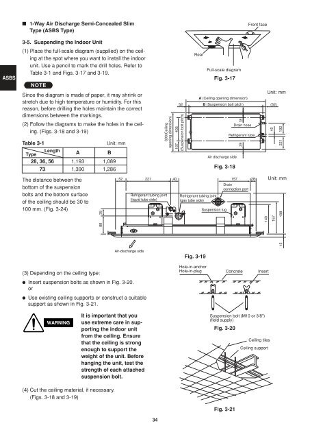
■ 1-Way Air Discharge Semi-Concealed Slim<br />
Type (ASBS Type)<br />
Front face<br />
ASBS<br />
3-5. Suspending the Indoor Unit<br />
(1) Place the full-scale diagram (supplied) on the ceiling<br />
at the spot where you want to install the indoor<br />
unit. Use a pencil to mark the drill holes. Refer to<br />
Table 3-1 and Figs. 3-17 and 3-19.<br />
NOTE<br />
Since the diagram is made of paper, it may shrink or<br />
stretch due to high temperature or humidity. For this<br />
reason, be<strong>for</strong>e drilling the holes maintain the correct<br />
dimensions between the markings.<br />
(2) Follow the diagrams to make the holes in the ceiling.<br />
(Figs. 3-18 and 3-19)<br />
Table 3-1<br />
Type<br />
Length<br />
A<br />
B<br />
28, 36, 56 1,193 1,089<br />
73 1,390 1,286<br />
The distance between the<br />
bottom of the suspension<br />
bolts and the bottom surface<br />
of the ceiling should be 30 to<br />
100 mm. (Fig. 3-24)<br />
88 35<br />
Unit: mm<br />
52<br />
690(Ceiling<br />
opening dimension)<br />
221 40<br />
Refrigerant tubing joint<br />
(liquid tube side)<br />
Rear<br />
Full-scale diagram<br />
Fig. 3-17<br />
A (Ceiling opening dimension)<br />
52 B (Suspension bolt pitch)<br />
(52)<br />
197 405<br />
(Suspension bolt pitch)<br />
Refrigerant tubing joint<br />
(gas tube side)<br />
Air discharge side<br />
Fig. 3-18<br />
Suspension lug<br />
18<br />
Drain hose<br />
Refrigerant tube<br />
39<br />
157 28<br />
Drain<br />
connection port<br />
140<br />
Unit: mm<br />
40<br />
192<br />
221<br />
Unit: mm<br />
157<br />
198<br />
15<br />
(3) Depending on the ceiling type:<br />
Air-discharge side<br />
● Insert suspension bolts as shown in Fig. 3-20.<br />
or<br />
● Use existing ceiling supports or construct a suitable<br />
support as shown in Fig. 3-21.<br />
Fig. 3-19<br />
Hole-in-anchor<br />
Hole-in-plug Concrete Insert<br />
WARNING<br />
It is important that you<br />
use extreme care in supporting<br />
the indoor unit<br />
from the ceiling. Ensure<br />
that the ceiling is strong<br />
enough to support the<br />
weight of the unit. Be<strong>for</strong>e<br />
hanging the unit, test the<br />
strength of each attached<br />
suspension bolt.<br />
Suspension bolt (M10 or 3/8")<br />
(field supply)<br />
Fig. 3-20<br />
Ceiling tiles<br />
Ceiling support<br />
(4) Cut the ceiling material, if necessary.<br />
(Figs. 3-18 and 3-19)<br />
Fig. 3-21<br />
34