06-065 Mini ECO-i II for ARGO - Package
06-065 Mini ECO-i II for ARGO - Package
06-065 Mini ECO-i II for ARGO - Package

You also want an ePaper? Increase the reach of your titles
YUMPU automatically turns print PDFs into web optimized ePapers that Google loves.
<strong>06</strong>-<strong>06</strong>5 <strong>Mini</strong> <strong>ECO</strong>-i <strong>II</strong> <strong>for</strong> <strong>ARGO</strong> 2/8/<strong>06</strong> 4:37 PM Page 14<br />
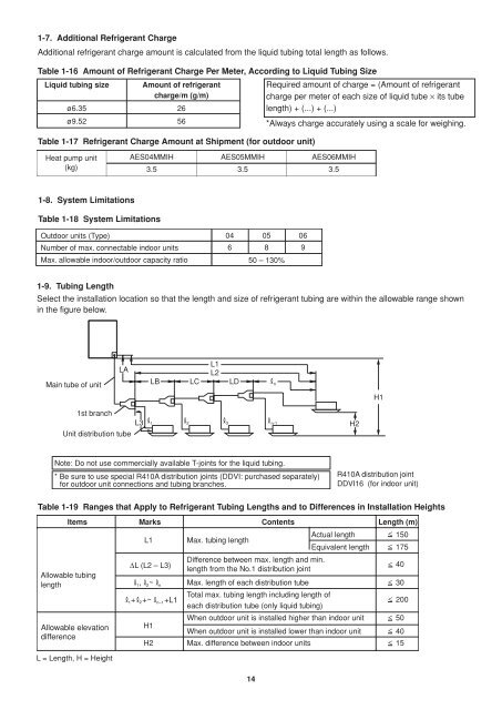
1-7. Additional Refrigerant Charge<br />
Additional refrigerant charge amount is calculated from the liquid tubing total length as follows.<br />
Table 1-16 Amount of Refrigerant Charge Per Meter, According to Liquid Tubing Size<br />
Liquid tubing size Amount of refrigerant<br />
charge/m (g/m)<br />
Required amount of charge = (Amount of refrigerant<br />
charge per meter of each size of liquid tube × its tube<br />
ø6.35 26<br />
length) + (...) + (...)<br />
ø9.52 56<br />
*Always charge accurately using a scale <strong>for</strong> weighing.<br />
Table 1-17 Refrigerant Charge Amount at Shipment (<strong>for</strong> outdoor unit)<br />
Heat pump unit<br />
(kg)<br />
AES04MMIH<br />
3.5<br />
AES05MMIH<br />
3.5<br />
AES<strong>06</strong>MMIH<br />
3.5<br />
1-8. System Limitations<br />
Table 1-18 System Limitations<br />
Outdoor units (Type) 04 05 <strong>06</strong><br />
Number of max. connectable indoor units<br />
6 8 9<br />
Max. allowable indoor/outdoor capacity ratio 50 – 130%<br />
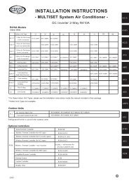
1-9. Tubing Length<br />
Select the installation location so that the length and size of refrigerant tubing are within the allowable range shown<br />
in the figure below.<br />
Main tube of unit<br />
LA<br />
LB<br />
LC<br />
L1<br />
L2<br />
LD<br />
n<br />
H1<br />
1st branch<br />
Unit distribution tube<br />
L3<br />
1 2 3 n-1<br />
H2<br />
Note: Do not use commercially available T-joints <strong>for</strong> the liquid tubing.<br />
* Be sure to use special R410A distribution joints (DDVI: purchased separately)<br />
<strong>for</strong> outdoor unit connections and tubing branches.<br />
R410A distribution joint<br />
DDVI16 (<strong>for</strong> indoor unit)<br />
Table 1-19 Ranges that Apply to Refrigerant Tubing Lengths and to Differences in Installation Heights<br />
Items Marks Contents Length (m)<br />
Allowable tubing<br />
length<br />
Allowable elevation<br />
difference<br />
L = Length, H = Height<br />
L1<br />
L (L2 – L3)<br />
Max. tubing length<br />
Difference between max. length and min.<br />
length from the No.1 distribution joint<br />
Actual length 150<br />
Equivalent length 175<br />
1, 2 ~ n Max. length of each distribution tube 30<br />
Total max. tubing length including length of<br />
1+ 2 +~ n–1 +L1<br />
each distribution tube (only liquid tubing)<br />
When outdoor unit is installed higher than indoor unit 50<br />
H1<br />
When outdoor unit is installed lower than indoor unit 40<br />
H2 Max. difference between indoor units 15<br />
><br />
><br />
><br />
><br />
><br />
><br />
><br />
><br />
40<br />
200<br />
14