06-065 Mini ECO-i II for ARGO - Package
06-065 Mini ECO-i II for ARGO - Package
06-065 Mini ECO-i II for ARGO - Package

Create successful ePaper yourself
Turn your PDF publications into a flip-book with our unique Google optimized e-Paper software.
<strong>06</strong>-<strong>06</strong>5 <strong>Mini</strong> <strong>ECO</strong>-i <strong>II</strong> <strong>for</strong> <strong>ARGO</strong> 2/8/<strong>06</strong> 4:37 PM Page 74<br />
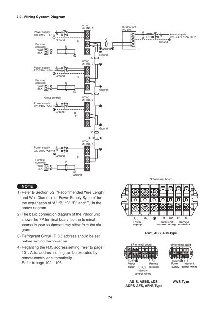
5-3. Wiring System Diagram<br />
Power supply L<br />
220-240V 50Hz<br />
N<br />
Remote<br />
controller<br />
WHT 1 1<br />
BLK 2 2<br />
Power supply L<br />
220-240V 50Hz N<br />
Remote<br />
controller<br />
WHT 1 1<br />
BLK 2 2<br />
Group control:<br />
Power supply L<br />
220-240V 50Hz N<br />
Ground<br />
Ground<br />
Ground<br />
D<br />
D<br />
B<br />
B<br />
B<br />
E<br />
Indoor<br />
unit (No. 1)<br />
1<br />
2<br />
3<br />
U1<br />
U2<br />
1<br />
2<br />
C<br />
Indoor<br />
unit (No. 2)<br />
1<br />
2<br />
3<br />
U1<br />
U2<br />
1<br />
2<br />
C<br />
Indoor<br />
unit (No. 3)<br />
1<br />
2<br />
3<br />
U1<br />
U2<br />
C<br />
Ground<br />
Ground<br />
Ground<br />
Outdoor unit<br />
INV unit<br />
L<br />
N<br />
1<br />
2<br />
A<br />
L<br />
N<br />
Ground<br />
Power supply<br />
220–240V-1N<br />
50Hz<br />
1<br />
2<br />
C<br />
Ground<br />
Power supply L<br />
220-240V 50Hz N<br />
Remote<br />
controller<br />
WHT 1 1<br />
BLK 2 2<br />
Ground<br />
D<br />
B<br />
Indoor<br />
unit (No. n)<br />
1<br />
2<br />
3<br />
U1<br />
U2<br />
1<br />
2<br />
NOTE<br />
Ground<br />
(1) Refer to Section 5-2. “Recommended Wire Length<br />
and Wire Diameter <strong>for</strong> Power Supply System” <strong>for</strong><br />
the explanation of “A,” “B,” “C,” “D,” and “E,” in the<br />
above diagram.<br />
(2) The basic connection diagram of the indoor unit<br />
shows the 7P terminal board, so the terminal<br />
boards in your equipment may differ from the diagram.<br />
(3) Refrigerant Circuit (R.C.) address should be set<br />
be<strong>for</strong>e turning the power on.<br />
(4) Regarding the R.C. address setting, refer to page<br />
101. Auto. address setting can be executed by<br />
remote controller automatically.<br />
Refer to page 102 – 1<strong>06</strong>.<br />
1(L) 2(N)<br />
Power<br />
supply<br />
8P terminal board<br />
1 2 U1 U2 R1 R2<br />
1(L)2(N)<br />
Power<br />
supply U1 U2<br />
Inter-unit<br />
R1 R2<br />
Remote<br />
controller<br />
control wiring<br />
7P terminal board<br />
U1 U2 R1 R2<br />
Inter-unit Remote<br />
control wiring controller<br />
AS2S, ASS, ACS Type<br />
5P terminal board<br />
1 2 3 4 5<br />
1(L)2(N) 4 5<br />
Power<br />
supply<br />
Inter-unit<br />
control wiring<br />
AS1S, ASBS, ADS,<br />
ADPS, AFS, AFNS Type<br />
AWS Type<br />
74