06-065 Mini ECO-i II for ARGO - Package
06-065 Mini ECO-i II for ARGO - Package
06-065 Mini ECO-i II for ARGO - Package

Create successful ePaper yourself
Turn your PDF publications into a flip-book with our unique Google optimized e-Paper software.
<strong>06</strong>-<strong>06</strong>5 <strong>Mini</strong> <strong>ECO</strong>-i <strong>II</strong> <strong>for</strong> <strong>ARGO</strong> 2/8/<strong>06</strong> 4:37 PM Page 48<br />
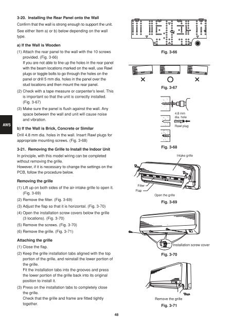
3-20. Installing the Rear Panel onto the Wall<br />
Confirm that the wall is strong enough to support the unit.<br />
See either Item a) or b) below depending on the wall<br />
type.<br />
AWS<br />
a) If the Wall is Wooden<br />
(1) Attach the rear panel to the wall with the 10 screws<br />
provided. (Fig. 3-66)<br />
If you are not able to line up the holes in the rear panel<br />
with the beam locations marked on the wall, use Rawl<br />
plugs or toggle bolts to go through the holes on the<br />
panel or drill 5 mm dia. holes in the panel over the<br />
stud locations and then mount the rear panel.<br />
(2) Check with a tape measure or carpenter’s level. This<br />
is important so that the unit is correctly installed.<br />
(Fig. 3-67)<br />
(3) Make sure the panel is flush against the wall. Any<br />
space between the wall and unit will cause noise<br />
and vibration.<br />
b) If the Wall is Brick, Concrete or Similar<br />
Drill 4.8 mm dia. holes in the wall. Insert Rawl plugs <strong>for</strong><br />
appropriate mounting screws. (Fig. 3-68)<br />
3-21. Removing the Grille to Install the Indoor Unit<br />
In principle, with this model wiring can be completed<br />
without removing the grille.<br />
However, if it is necessary to change the settings on the<br />
PCB, follow the procedure below.<br />
Fig. 3-66<br />
Fig. 3-67<br />
Fig. 3-68<br />
4.8 mm<br />
dia. hole<br />
Rawl plug<br />
Intake grille<br />
Removing the grille<br />
(1) Lift up on both sides of the air-intake grille to open it.<br />
(Fig. 3-69)<br />
(2) Remove the filter. (Fig. 3-69)<br />
(3) Adjust the flap so that it is horizontal. (Fig. 3-70)<br />
(4) Open the installation screw covers below the grille<br />
(3 locations). (Fig. 3-70)<br />
(5) Remove the screws. (Fig. 3-70)<br />
(6) Remove the grille. (Fig. 3-71)<br />
Attaching the grille<br />
(1) Close the flap.<br />
(2) Keep the grille installation tabs aligned with the top<br />
portion of the grille, and reinstall the lower portion of<br />
the grille.<br />
Fit the installation tabs into the grooves and press<br />
the lower portion of the grille back into its original<br />
position to install it.<br />
(3) Press on the installation tabs to completely close<br />
the grille.<br />
Check that the grille and frame are fitted tightly<br />
together.<br />
Filter<br />
Flap<br />
Open the grille<br />
Fig. 3-69<br />
Installation screw cover<br />
Fig. 3-70<br />
Remove the grille<br />
Fig. 3-71<br />
48