10Gbps Optical Receiver and VCSEL Driver in 0.13um CMOS ...
10Gbps Optical Receiver and VCSEL Driver in 0.13um CMOS ...
10Gbps Optical Receiver and VCSEL Driver in 0.13um CMOS ...

Create successful ePaper yourself
Turn your PDF publications into a flip-book with our unique Google optimized e-Paper software.
2.2.1 TIA Input Configuration<br />
R D1<br />
i <strong>in</strong><br />
C PD<br />
R F<br />
M 2<br />
M 3<br />
M 1<br />
R <strong>in</strong><br />
C <strong>in</strong><br />
v out<br />
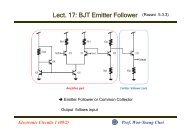
Figure 2.11 Conventional Common-Source TIA<br />
Fig 2.11 shows the conventional common-source TIA. It suffers<br />
from serious design tradeoffs between the transimpedance ga<strong>in</strong> (Z T ) , 3-<br />
dB b<strong>and</strong>width (BW 3-dB ), <strong>and</strong> photodiode parasitic capacitance (C PD ).<br />
The b<strong>and</strong>width <strong>and</strong> transimpedance ga<strong>in</strong> of the common-source TIA is<br />
given by:<br />
Z<br />
T<br />
=<br />
A<br />
⋅ R<br />
A + 1<br />
F<br />
≈ R<br />
F<br />
(2.11)<br />
BW<br />
3−dB<br />
≈<br />
2πR<br />
F<br />
A + 1<br />
( C + C<br />
PD<br />
<strong>in</strong><br />
)<br />
(2.12)<br />
where A is the open-loop voltage ga<strong>in</strong> of TIA, R F is the feedback<br />
resistance, <strong>and</strong> C <strong>in</strong> is the <strong>in</strong>put parasitic capacitance <strong>in</strong>clud<strong>in</strong>g the ESD<br />
protection diode pad parasitic capacitance <strong>and</strong> the gate capacitance of<br />
M 1 . For a given C PD , R F is directly proportional to Z T , while is<br />
20