Instruction manual - Mettler-Toledo
Instruction manual - Mettler-Toledo
Instruction manual - Mettler-Toledo

Create successful ePaper yourself
Turn your PDF publications into a flip-book with our unique Google optimized e-Paper software.
<strong>Instruction</strong> <strong>manual</strong><br />
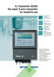
O 2 Transmitter 4100 e<br />
Order number: 52 121 114
Warranty<br />
Defects occurring within 1 year from delivery date shall be remedied free<br />
of charge at our plant (carriage and insurance paid by sender).<br />
Subject to change without notice<br />
Return of products under warranty<br />
Please contact METTLER TOLEDO’s Customer Service Dept. before returning<br />
a defective device. Ship the cleaned device to the address you have been<br />
given. If the device has been in contact with process fluids, it must be<br />
decontaminated/disinfected before shipment. In that case, please attach a<br />
corresponding certificate, for the health and safety of our service personnel.<br />
Disposal (Directive 2002/96/EC of January 27, 2003)<br />
Please observe the applicable local or national regulations<br />
concerning the disposal of “waste electrical and electronic<br />
equipment”.<br />
<strong>Mettler</strong>-<strong>Toledo</strong> GmbH, Process Analytics, Industrie Nord,<br />
CH-8902 Urdorf, Tel. (01) 736 26 36<br />
Subject to technical changes. <strong>Mettler</strong>-<strong>Toledo</strong> GmbH, 10/03.<br />
Printed in Germany.<br />
Contents<br />
Safety information . . . . . . . . . . . . . . . . . . . . . . . . . . . . . . .5<br />
Intended use . . . . . . . . . . . . . . . . . . . . . . . . . . . . . . . . . . . . . . . . . . . . . . .6<br />
Trademarks . . . . . . . . . . . . . . . . . . . . . . . . . . . . . . . . . . . . . . . . . . . . . . . .6<br />
EC Declaration of Conformity . . . . . . . . . . . . . . . . . . . . . . .7<br />
Overview of O 2 Transmitter 4100 e . . . . . . . . . . . . . . . . . .9<br />
Assembly . . . . . . . . . . . . . . . . . . . . . . . . . . . . . . . . . . . . . . .10<br />
Package contents . . . . . . . . . . . . . . . . . . . . . . . . . . . . . . . . . . . . . . . . . .10<br />
Mounting plan . . . . . . . . . . . . . . . . . . . . . . . . . . . . . . . . . . . . . . . . . . . .11<br />
Pipe mounting, panel mounting . . . . . . . . . . . . . . . . . . . . . . . . . . . . . . .12<br />
Installation and connection . . . . . . . . . . . . . . . . . . . . . . .14<br />
Information on installation . . . . . . . . . . . . . . . . . . . . . . . . . . . . . . . . . . .14<br />
Terminal assignments . . . . . . . . . . . . . . . . . . . . . . . . . . . . . . . . . . . . . . .14<br />
Typical wiring . . . . . . . . . . . . . . . . . . . . . . . . . . . . . . . . . . . . . . . . . . . . .17<br />
Protective wiring of relay outputs . . . . . . . . . . . . . . . . . . . . . . . . . . . . . .18<br />
User interface and display . . . . . . . . . . . . . . . . . . . . . . . .20<br />
Operation: Keypad . . . . . . . . . . . . . . . . . . . . . . . . . . . . . . .22<br />
Safety features . . . . . . . . . . . . . . . . . . . . . . . . . . . . . . . . .23<br />
Sensocheck, Sensoface sensor monitoring . . . . . . . . . . . . . . . . . . . . . . . .23<br />
GainCheck device self test . . . . . . . . . . . . . . . . . . . . . . . . . . . . . . . . . . . .23<br />
Automatic device self-test . . . . . . . . . . . . . . . . . . . . . . . . . . . . . . . . . . . .23<br />
Hold mode . . . . . . . . . . . . . . . . . . . . . . . . . . . . . . . . . . . . . . . . . . . . . .24<br />
To activate the Hold mode from outside . . . . . . . . . . . . . . . . . . . . . . . . .24<br />
Mode codes . . . . . . . . . . . . . . . . . . . . . . . . . . . . . . . . . . . .25<br />
Configuration . . . . . . . . . . . . . . . . . . . . . . . . . . . . . . . . . . .26<br />
Menu structure of configuration . . . . . . . . . . . . . . . . . . . . . . . . . . . . . . .27<br />
Overview of configuration steps . . . . . . . . . . . . . . . . . . . . . . . . . . . . . . .28<br />
Output 1 . . . . . . . . . . . . . . . . . . . . . . . . . . . . . . . . . . . . . . . . . . . . . . . . .30<br />
Output 2 . . . . . . . . . . . . . . . . . . . . . . . . . . . . . . . . . . . . . . . . . . . . . . . . .38<br />
Correction . . . . . . . . . . . . . . . . . . . . . . . . . . . . . . . . . . . . . . . . . . . . . . . .44<br />
Calibration mode, alarm settings . . . . . . . . . . . . . . . . . . . . . . . . . . . . . . .46<br />
Limit function . . . . . . . . . . . . . . . . . . . . . . . . . . . . . . . . . . . . . . . . . . . . .48<br />
Controller . . . . . . . . . . . . . . . . . . . . . . . . . . . . . . . . . . . . . . . . . . . . . . . .52<br />
Control of rinsing or calibration systems . . . . . . . . . . . . . . . . . . . . . . . . .54<br />
3
Contents<br />
Parameter set 1/2 . . . . . . . . . . . . . . . . . . . . . . . . . . . . . . . .56<br />
Default settings of parameter sets . . . . . . . . . . . . . . . . . . . . . . . . . . . . . .57<br />
Parameter set, individual settings . . . . . . . . . . . . . . . . . . . . . . . . . . . . . .58<br />
Calibration . . . . . . . . . . . . . . . . . . . . . . . . . . . . . . . . . . . . .60<br />
Calibration to saturation (SAT) . . . . . . . . . . . . . . . . . . . . . . . . . . . . . . . . .62<br />
Calibration to concentration (Conc) . . . . . . . . . . . . . . . . . . . . . . . . . . . .64<br />
Zero calibration . . . . . . . . . . . . . . . . . . . . . . . . . . . . . . . . . . . . . . . . . . .66<br />
Product calibration . . . . . . . . . . . . . . . . . . . . . . . . . . . . . . . . . . . . . . . . .68<br />
Adjusting temp probe . . . . . . . . . . . . . . . . . . . . . . . . . . . . . . . . . . . . . .70<br />
Measurement . . . . . . . . . . . . . . . . . . . . . . . . . . . . . . . . . .70<br />
Diagnostics functions . . . . . . . . . . . . . . . . . . . . . . . . . . . .71<br />
Controller functions . . . . . . . . . . . . . . . . . . . . . . . . . . . . . .74<br />
PID controller . . . . . . . . . . . . . . . . . . . . . . . . . . . . . . . . . . . . . . . . . . . . .74<br />
Pulse length / pulse frequency controller . . . . . . . . . . . . . . . . . . . . . . . . .76<br />
Connecting a rinsing system . . . . . . . . . . . . . . . . . . . . . . .77<br />
Operation with automatic cleaning system . . . . . . . . . .77<br />
Error messages (error codes) . . . . . . . . . . . . . . . . . . . . . .78<br />
Calibration error messages . . . . . . . . . . . . . . . . . . . . . . . . . . . . . . . . . . .80<br />
Operating states . . . . . . . . . . . . . . . . . . . . . . . . . . . . . . . . .78<br />
Sensoface . . . . . . . . . . . . . . . . . . . . . . . . . . . . . . . . . . . . . .82<br />
Sensocheck . . . . . . . . . . . . . . . . . . . . . . . . . . . . . . . . . . . . . . . . . . . . . .83<br />
Appendix . . . . . . . . . . . . . . . . . . . . . . . . . . . . . . . . . . . . . . .85<br />
Product line and accessries . . . . . . . . . . . . . . . . . . . . . . . . . . . . . . . . . . .85<br />
Specifications . . . . . . . . . . . . . . . . . . . . . . . . . . . . . . . . . . . . . . . . . . . . .86<br />
Explosion protection . . . . . . . . . . . . . . . . . . . . . . . . . . . . . . . . . . . . . . . .92<br />
Warnings and notes to ensure safe operation . . . . . . . . . . . . . . . . . . . .93<br />
Control Drawing CSA . . . . . . . . . . . . . . . . . . . . . . . . . . . . . . . . . . . . . . .94<br />
Index . . . . . . . . . . . . . . . . . . . . . . . . . . . . . . . . . . . . . . . . . .98<br />
Safety information<br />
Be sure to read and observe the following instructions!<br />
The device has been designed in accordance with the state of<br />
the art and complying with the applicable safety regulations.<br />
When operating the device, certain conditions may nevertheless<br />
lead to danger for the operator or damage to the device.<br />
Caution!<br />
Commissioning may only be carried out by trained experts.<br />
Whenever it is likely that protection has been impaired, the<br />
device shall be made inoperative and secured against unintended<br />
operation.<br />
The protection is likely to be impaired if, for example:<br />
• the device shows visible damage<br />
• the device fails to perform the intended measurements<br />
• after prolonged storage at temperatures above 70 °C<br />
• after severe transport stresses<br />
Before recommissioning the device, a professional routine test<br />
in accordance with EN 61010-1 must be performed. This test<br />
should be carried out by the manufacturer.<br />
4 O 2 4100 e<br />
5
Intended use<br />
The O 2 Transmitter 4100 e is used for dissolved oxygen and temperature<br />
measurement in biotechnology, pharmaceutical industry,<br />
as well as in the field of environment, food processing, and<br />
sewage treatment.<br />
The rugged molded enclosure can be wall or pipe mounted or<br />
fixed into a control panel.<br />
The protective hood provides additional protection against direct<br />
weather exposure and mechanical damage.<br />
The Transmitter has been designed for application with amperometric<br />
sensors of the InPro6000 ... InPro6800 Series.<br />
EC Declaration of conformity<br />
Trademarks<br />
The following names are registered trademarks. For practical reasons<br />
they are shown without trademark symbol in this <strong>manual</strong>.<br />
InPro ®<br />
EasyClean ® 7<br />
6 O 2 4100 e
Overview of O 2 Transmitter 4100 e<br />
Do not<br />
connect!<br />
1<br />
Output 1<br />
9<br />
+ Output 1<br />
Cathode<br />
2<br />
10<br />
- Output 1/2<br />
Guard<br />
3<br />
DO<br />
input<br />
Output 2<br />
11<br />
+ Output 2<br />
Reference<br />
electrode<br />
4<br />
R1<br />
12<br />
Relay 1<br />
Anode<br />
5<br />
13<br />
Relay 1/2<br />
RTD<br />
RTD<br />
shield<br />
E<br />
D<br />
C<br />
Temp<br />
input<br />
R2<br />
Alarm<br />
Clean<br />
14<br />
15<br />
16<br />
17<br />
Relay 2<br />
Alarm<br />
Alarm<br />
Clean<br />
HOLD<br />
HOLD/<br />
CONTROL<br />
CONTROL<br />
6<br />
7<br />
8<br />
Hold<br />
Control<br />
input<br />
input<br />
Power<br />
18<br />
19<br />
20<br />
Clean<br />
Power<br />
Power<br />
8 O 2 4100 e 9
Assembly<br />
Package contents<br />
Check the shipment for transport damage and completeness.<br />
The package should contain:<br />
• Front unit<br />
• Lower case<br />
• Bag containing small parts<br />
• <strong>Instruction</strong> <strong>manual</strong><br />
• Specific test report<br />
Mounting plan<br />
144<br />
144<br />
105<br />
27<br />
11<br />
10<br />
9<br />
8<br />
7 6 5 4<br />
1<br />
2<br />
3<br />
15<br />
72<br />
6,2<br />
32<br />
42<br />
84<br />
80<br />
3<br />
21<br />
43<br />
1 2<br />
1 Cable gland (3 pieces)<br />
2 Breakthroughs for cable gland<br />
or conduit 1/2”,<br />
dia 21.5 mm (2 breakthroughs)<br />
Conduits not included!<br />
3 Breakthroughs for pipe mounting<br />
(4 breakthroughs)<br />
4 Breakthroughs for wall mounting<br />
(2 breakthroughs)<br />
1 Jumper (2 pieces)<br />
2 Washer (1 piece), for conduit<br />
mounting: Place washer between<br />
enclosure and nut<br />
3 Cable ties (3 pieces)<br />
4 Hinge pin (1 piece), insertable<br />
from either side<br />
5 Enclosure screws (4 pieces)<br />
6 Sealing inserts (1 piece)<br />
7 Rubber reducer (1 piece)<br />
8 Cable glands (3 pieces)<br />
9 Filler plugs (3 pieces)<br />
10 Hexagon nuts (5 pieces)<br />
11 Sealing plugs (2 pieces),<br />
for sealing in case of wall<br />
mounting<br />
Fig.: Mounting plan<br />
4<br />
Fig.: Assembling the enclosure<br />
10 O 2 4100 e<br />
11
Pipe mounting, panel mounting<br />
40 60<br />
2<br />
3<br />
4<br />
132<br />
1<br />
max. 25<br />
78 27<br />
1<br />
1 Screws (4 pieces)<br />
2 Gasket (1 piece)<br />
3 Control panel<br />
4 Span pieces (4 pieces)<br />
5 Threaded sleeves (4 pieces)<br />
5<br />
4<br />
5<br />
1 protective hood (if required)<br />
2 Hose clamps with worm gear drive to DIN 3017 (2 pieces)<br />
3 Pipe-mount plate (1 piece)<br />
4 For vertical or horizontal posts or pipes<br />
5 Self-tapping screws (4 pieces)<br />
2<br />
1...22 3<br />
Fig.: Panel-mount kit<br />
Fig.: Pipe-mount kit<br />
165<br />
132<br />
1<br />
1<br />
173<br />
Fig.: Protective hood for wall and pipe mounting<br />
12 O 2 4100 e<br />
13
Installation and connection<br />
Information on installation<br />
Caution!<br />
• Installation may only be carried out by trained experts in<br />
accordance with this instruction <strong>manual</strong> and as per applicable<br />
local and national codes.<br />
• Be sure to observe the technical specifications and input ratings.<br />
• Be sure not to notch the conductor when stripping the insulation.<br />
• Before connecting the device to the power supply, make sure<br />
that its voltage lies within the range 20.5 to 253 V AC/DC.<br />
• When commissioning, a complete configuration must be<br />
carried out by the system administrator.<br />
4<br />
3<br />
1<br />
The terminals are suitable for single wires and flexible leads up<br />
to 2.5 mm 2 (AWG 14)<br />
Warning!<br />
Additional safety precautions have to be taken for applications in<br />
hazardous locations to CSA (CLI DIV2 GPA,B,C,D T4, Ex nA IIC T4)!<br />
(See Pg 93.)<br />
Terminal assignments<br />
Fig.: Terminal assignments O 2 Transmitter 4100 e<br />
14 O 2 4100 e<br />
1 ESD shield covering the sensor inputs<br />
(Screw off for assembly)<br />
Note: The cable shield must end under the ESD shield.<br />
(Cut lines if required)<br />
2 Terminals for temperature probe<br />
3 Terminals for sensor<br />
4 Connection of power supply<br />
Fig.: Information on installation, rear side of Transmitter<br />
Division 2 wiring<br />
The connections to the Transmitter are incendive and<br />
must be installed in accordance with the National<br />
Electric Code (ANSI-NFPA 70) Division 2 hazardous<br />
(classified) location incendive wiring techniques.<br />
2<br />
15
Typical wiring<br />
Sensors with connection via VP cable<br />
blue<br />
gray<br />
green<br />
white<br />
red<br />
transparent<br />
yellow/green<br />
Sensor<br />
Connection Terminal VP cable<br />
1 not connected<br />
cathode 2 transparent (coax core)<br />
guard 3 not connected<br />
ref. el. 4 (jumper 4-5)<br />
anode 5 red (coax shield)<br />
RTD E green<br />
RTD D white<br />
shield C yellow/green<br />
*gray, blue: not connected<br />
16 O 2 4100e 17
Protective wiring<br />
Protective wiring of switching contacts<br />
Relay contacts are subjected to electrical erosion. Especially<br />
with inductive and capacitive loads, the service life of the contacts<br />
will be reduced. For suppression of sparks and arcing,<br />
components such as RC combinations, nonlinear resistors,<br />
series resistors and diodes should be used.<br />
Protective wiring<br />
Typical protective wiring measures<br />
Typical AC applications<br />
with inductive load<br />
1 2<br />
3<br />
1<br />
3<br />
2<br />
1 Load<br />
2 RC combination, e.g. RIFA PMR 209<br />
Typical RC combinations<br />
for 230 V AC:<br />
Capacitor 0.1µF / 630V,<br />
Resistor 100 Ohms / 1 W<br />
3 Contact<br />
A: DC application with inductive load<br />
B: AC/DC applications with capacitive load<br />
C: Connection of incandescent lamps<br />
A1<br />
A2<br />
A3<br />
B1<br />
B2<br />
B3<br />
C1<br />
C3<br />
Inductive load<br />
Free-wheeling diode, e.g. 1N4007 (Observe polarity)<br />
Contact<br />
Capacitive load<br />
Resistor, e.g. 8 Ohms/1 W at 24 V / 0.3 A<br />
Contact<br />
Incandescent lamp, max 60 W / 230 V, 30 W / 115 V<br />
Contact<br />
Warning!<br />
Make sure that the maximum ratings of the relay<br />
contacts are not exceeded even during switching!<br />
18 O 2 4100 e 19
User interface, display<br />
User interface<br />
Display<br />
1 2 3 4 5 6 7 8 9 10<br />
20<br />
19<br />
18<br />
11<br />
12<br />
13<br />
1 Display<br />
2 Mode indicators (no keys),<br />
from left to right:<br />
- Measuring mode<br />
- Calibration mode<br />
- Alarm<br />
- Wash contact<br />
- Configuration mode<br />
3 Keypad<br />
4 Coding<br />
5 Rating plate<br />
6 Model designation<br />
7 Alarm LED<br />
20 O 2 4100 e 21<br />
17 16<br />
1 Mode code entry<br />
2 Display of meas. variable*<br />
3 Temperature<br />
4 Current output<br />
5 Limit values<br />
6 Alarm<br />
7 Sensocheck<br />
8 Calibration<br />
9 Interval/response time<br />
10 Wash contact<br />
11 Measurement symbols<br />
12 Proceed with enter<br />
13 Bar for identifying the device<br />
status, above mode indicators,<br />
from left to right:<br />
- Measuring mode<br />
- Calibration mode<br />
- Alarm<br />
- Wash contact<br />
- Configuration mode<br />
15 14<br />
14 Lower display<br />
15 Manual temp indicator<br />
16 Hold mode active<br />
17 Waiting time running<br />
18 Sensor data<br />
19 Main display<br />
20 Sensoface<br />
* Not in use
Operation: Keypad<br />
Start, end calibration<br />
Start, end configuration<br />
Safety features<br />
Sensocheck, Sensoface sensor monitoring<br />
Sensocheck continuously monitors the sensor and leads.<br />
Sensocheck can be switched off (Configuration, Pg 46).<br />
+<br />
Select digit position<br />
(selected position flashes)<br />
Edit digit<br />
• Calibration:<br />
Continue in program sequence<br />
• Configuration: Confirm entries,<br />
next configuration step<br />
• Measuring mode: Display output current<br />
Cal Info, display of zero current<br />
and slope<br />
Error Info, display last error message<br />
Start GainCheck device self-test<br />
Sensoface provides information on the sensor condition.<br />
The zero point, slope and response time during calibration<br />
are evaluated. The three Sensoface indicators provide<br />
the user with information about wear and required<br />
maintenance of the sensor.<br />
GainCheck device self test<br />
A display test is carried out, the software version is displayed<br />
and the memory and measured value transfer are checked.<br />
Start GainCheck device self-test:<br />
Automatic device self-test<br />
The automatic device self-test checks the memory and measured-value<br />
transfer. It runs automatically in the background at<br />
fixed intervals.<br />
+<br />
22 O 2 4100 e 23
Safety features<br />
Hold mode<br />
Display:<br />
The Hold mode is a safety mode during configuration and calibration.<br />
Output current is frozen (Last) or set to a fixed value<br />
(Fix). Alarm and limit contacts are disabled.<br />
If the calibration or configuration mode is exited, the<br />
Transmitter remains in the Hold mode for safety reasons. This<br />
prevents undesirable reactions of the connected peripherals<br />
due to incorrect configuration or calibration. The measured<br />
value and “HOLD” are displayed alternately. The Transmitter<br />
only returns to measuring mode after enter is pressed and a<br />
waiting time of 20 s has passed.<br />
To activate the Hold mode from outside<br />
The Hold mode can be activated from outside by sending a<br />
signal to the Hold input (e.g. from the process control system).<br />
Hold<br />
6<br />
Power supply<br />
12...24 V AC/DC<br />
Mode codes<br />
The mode codes allow fast access to all functions<br />
Calibration<br />
Key + Code<br />
0000<br />
1001<br />
1100<br />
1105<br />
1015<br />
Configuration<br />
Key + Code<br />
0000<br />
1200<br />
2222<br />
7654<br />
Description<br />
Cal Info<br />
Display of zero point and slope<br />
Zero point calibration<br />
Adjusting the zero point (sensor)<br />
Slope calibration<br />
Adjusting the slope (sensor)<br />
Product calibration<br />
Adjusting the zero / slope (product)<br />
Temperature probe<br />
Temperature probe adjustment<br />
Description<br />
Error Info Display last error and erase<br />
Configuration<br />
Sensor monitor<br />
Display uncorrected sensor current (nA)<br />
Parameter set 1/2 Selecting parameter set<br />
input<br />
7<br />
5555<br />
Current source 1 Output current 1 specified<br />
O 2 4100 e<br />
Hold active Hold inactive<br />
10 ... 30 V AC/DC 0 ... 2 V AC/DC<br />
Process control system (PCS)<br />
5556<br />
5557<br />
5559<br />
Current source 2 Output current 2 specified<br />
Relay test Manual test of contacts<br />
Manual controller<br />
Manual specification of controller output<br />
24 O 2 4100 e<br />
25
Configuration<br />
In the Configuration mode you set the device parameters.<br />
Menu structure of configuration<br />
Activate<br />
Activate with conf<br />
Enter mode code “1200”<br />
Edit parameter with and ,<br />
confirm/continue with enter.<br />
(End with conf enter.)<br />
The configuration steps are assigned to different menu groups.<br />
With the arrow keys you can jump between the individual menu groups.<br />
Each menu group contains menu items for setting the parameters.<br />
Pressing enter opens a menu item. The values are edited using the arrow<br />
keys. Pressing enter confirms/stores the settings.<br />
Return to measurement: Press conf key.<br />
Hold<br />
HOLD icon<br />
During configuration the Transmitter<br />
remains in the Hold mode for reasons<br />
of safety. The output current is frozen<br />
(at its last value or at a preset fixed<br />
value, depending on the configuration),<br />
limit and alarm contacts are<br />
inactive. The controller is in the configured<br />
state, Sensoface is off, mode<br />
indicator “Configuration” is on.<br />
Select menu group<br />
Menu group Code Display<br />
Output 1 o1.<br />
Menu item 1<br />
Menu item 2<br />
Select menu item<br />
Menu item ...<br />
Input errors<br />
The configuration parameters are<br />
checked during the input. In the case<br />
of an incorrect input “Err” is displayed<br />
for approx. 3 s. The incorrect<br />
parameters cannot be stored. Input<br />
must be repeated.<br />
Output 2 o2.<br />
Correction CO.<br />
Calibration mode CA.<br />
End<br />
End with conf. The measured value<br />
and Hold are displayed alternately,<br />
“enter” flashes. End Hold mode with<br />
enter. The display shows the measured<br />
value. The output current<br />
remains frozen for another 20 s<br />
(HOLD icon on, “hourglass” flashes).<br />
Alarm<br />
settings<br />
Relay / Controller<br />
Rinsing and<br />
cleaning probes<br />
AL.<br />
rL.<br />
Pb.<br />
Previous<br />
menu group:<br />
26 O 2 4100 e<br />
27
Overview of configuration steps<br />
Code<br />
Menu<br />
Choices<br />
Code<br />
Choices<br />
Auswahl<br />
out1 Output 1<br />
o1. Select sensor type Standard (Type A) / Traces (Type B)<br />
Select saturation / concentration<br />
Select current range<br />
Enter current beginning<br />
Enter current end<br />
Time constant of output filter<br />
% / mg/l, ppm<br />
0-20 mA / 4-20 mA<br />
xxxx<br />
xxxx<br />
xxxx s<br />
22 mA signal in the case of error ON / OFF<br />
Signal behavior during HOLD<br />
out2 Output 2<br />
Enter fixed value<br />
Last / Fix<br />
xxx.x mA<br />
o2. Select temperature unit °C / °F<br />
Corr<br />
Select temperature probe<br />
Select current range<br />
Enter current beginning<br />
Enter current end<br />
Time constant of output filter<br />
22NTC / 30NTC<br />
0-20 mA / 4-20 mA<br />
xxx.x<br />
xxx.x<br />
xxxx s<br />
22 mA signal in the case of temp error ON / OFF<br />
Signal behavior during HOLD<br />
Correction<br />
Enter fixed value<br />
Last / Fix<br />
xxx.x mA<br />
Co. Enter polarization voltage 0675 mV / xxxx mV<br />
CAL<br />
Select pressure unit<br />
Select process pressure correction<br />
Enter salt correction<br />
Calibration mode<br />
bar / kPa / PSi<br />
x.xxx bar / 1.013 bar<br />
xx.xx mg/l<br />
CA. Select saturation / concentration SAt / Conc<br />
Enter cal timer interval<br />
xxxx h<br />
ALr Alarm settings<br />
AL. Select Sensocheck ON / OFF<br />
Enter alarm delay<br />
xxxx s<br />
LED in HOLD mode<br />
ON / OFF<br />
rLAY Relay 1/2: Limit values, controller<br />
rL. Select limit function / controller LiMIT / CtROL<br />
L1. Select contact function Lo / Hi<br />
Select contact response N/O / N/C<br />
Enter switching point xxxx<br />
Enter hysteresis<br />
xxxx<br />
Enter delay<br />
xxxx SEC<br />
L2. Select contact function xxxx s<br />
Select contact response N/O / N/C<br />
Enter switching point xxxx<br />
Enter hysteresis<br />
xxxx<br />
Enter delay<br />
xxxx SEC<br />
Ct. Enter controller setpoint xxxx<br />
Enter neutral zone xxxx<br />
(P) Controller gain KP xxxx %<br />
(I) Reset time TR<br />
xxxx SEC<br />
(D) Rate time TD<br />
xxxx SEC<br />
Pulse length /Pulse frequency PLC / PFC<br />
PLC: Pulse length<br />
xxxx SEC<br />
PFC: Pulse frequency xxxx /min<br />
Select HOLD behavior Y Last / Y Off<br />
PrbE Rinsing and cleaning probes<br />
Pb. Select rinsing/cleaning probe EASYCLN / rinse<br />
rinse Rinsing interval<br />
xxx.x h<br />
Rinse duration<br />
xxxx SEC<br />
Contact response<br />
N/O / N/C<br />
EASYCLN Cleaning interval<br />
xxx.x h<br />
Lock cleaning interval Off / On<br />
28 O 2 4100 e<br />
29
Configuration<br />
Output 1<br />
Select sensor type. Measurement procedure.<br />
Code Display Action Choices<br />
Menu group<br />
Code<br />
Output 1 o1.<br />
Display<br />
Select menu item<br />
Select sensor type*<br />
Select meas. procedure<br />
Select 0-20 / 4-20 mA<br />
Enter current beginning<br />
o1. Select configuration<br />
(Press conf key).<br />
After correct input a welcome<br />
text is displayed for<br />
approx. 3 s<br />
Enter mode code “1200”<br />
(Select position using arrow key<br />
and edit number using . When<br />
the display reads “1200”, press<br />
enter to confirm.)<br />
Enter current end<br />
Set output filter<br />
22 mA in the case of error<br />
Hold mode<br />
The Transmitter is in HOLD mode<br />
(HOLD icon is on).<br />
Select sensor Type A / B<br />
(see table on left-hand side)<br />
Select with key<br />
Proceed with enter<br />
Type A<br />
InPro<br />
6000–6800<br />
Type B<br />
InPro6900<br />
End:<br />
Press conf, then enter<br />
* Sensor Type A (standard applications)<br />
Sensor type<br />
Screw cap Sensor current in air (25 °C) Detection<br />
limit<br />
InPro 6800 VP typ. 60 nA 0.006 ppm<br />
* Sensor Type B (traces)<br />
Sensor type<br />
Screw cap<br />
Sensor current in air (25 °C)<br />
Detection<br />
limit<br />
InPro 6900 VP typ. 350 nA 0.001 ppm<br />
Select measurement procedure<br />
(valid for all following settings):<br />
• SAt: Saturation (%)<br />
• Conc: Concentration (mg/l<br />
or ppm)<br />
Select with key<br />
Proceed with enter<br />
%<br />
mg/l<br />
ppm<br />
Note: The Transmitter 4100 e has a device a resolution of 0.01 ppm.<br />
For the sensor type B, we recommend the O 2 Transmitter 4100ppb<br />
with a device resolution of 0.001 ppm.<br />
30 O 2 4100 e<br />
Note: Characters represented in gray are flashing and can be edited.<br />
31
Configuration<br />
Output 1<br />
Output current range. Current beginning. Current end.<br />
Menu group<br />
Output 1 o1.<br />
Code Display<br />
Select menu item<br />
Select sensor type<br />
Select meas. procedure<br />
Select 0-20 / 4-20 mA<br />
Enter current beginning<br />
Enter current end<br />
Set output filter<br />
22 mA in the case of error<br />
Hold mode<br />
Code Display Action Choices<br />
o1. Set output current range<br />
Select with key<br />
Proceed with enter<br />
Current beginning<br />
Enter lower end of scale,<br />
depending on the measurement<br />
procedure selected<br />
(Saturation or Concentration)<br />
Select with key, edit number<br />
with key, proceed with enter<br />
Current end<br />
Enter upper end of scale, depending<br />
on the measurement procedure<br />
selected (Saturation or<br />
Concentration)<br />
Select with key, edit number<br />
with key, proceed with enter<br />
4 - 20 mA<br />
(0 - 20 mA)<br />
0000 %<br />
(mg/l,<br />
ppm)<br />
0100 %<br />
(mg/l,<br />
ppm)<br />
Assignment of measured values:<br />
Current beginning and current end<br />
Example 1: Range 0 to 100 % Example 2: Range 50 to 70%.<br />
Advantage: Higher resolution in<br />
range of interest<br />
[%]<br />
100<br />
Oxygen saturation<br />
[%]<br />
70<br />
Oxygen saturation<br />
End:<br />
Press conf, then enter<br />
32 O 2 4100 e<br />
0<br />
4<br />
Output current<br />
20<br />
[mA]<br />
50<br />
4<br />
Output current<br />
20 [mA]<br />
33
Configuration<br />
Output 1<br />
Time constant of output filter.<br />
Menu group<br />
Output 1 o1.<br />
Code Display<br />
Select menu item<br />
Select sensor type<br />
Select meas. procedure<br />
Select 0-20 / 4-20 mA<br />
Enter current beginning<br />
Enter current end<br />
Set output filter<br />
22 mA in the case of error<br />
Hold mode<br />
Code Display Action Choices<br />
o1. Time constant of output filter<br />
Default setting: 0 s (inactive).<br />
To specify a time constant:<br />
Select with key, edit number<br />
with key, proceed with enter<br />
0 s<br />
(0 – 120 s)<br />
Time constant of output filter<br />
To smoothen the current output, a low-pass filter with<br />
adjustable filter time constant can be switched on. When there<br />
is a jump at the input (100 %), the output level is 63 % after<br />
the time constant has been reached.<br />
The time constant can be set from 0 to 120 s.<br />
If the time constant is set to 0 s, the current output follows the<br />
input.<br />
Note:<br />
The filter only acts on the current output, not on the display, the<br />
limit values, or the controller!<br />
Time constant 0 to 120 s<br />
End:<br />
Press conf, then enter<br />
34 O 2 4100 e<br />
35
Configuration<br />
Output 1<br />
Output current during Error and HOLD.<br />
Menu group<br />
Output 1 o1.<br />
Code Display<br />
Select menu item<br />
Select sensor type<br />
Select meas. procedure<br />
Select 0-20 / 4-20 mA<br />
Enter current beginning<br />
Enter current end<br />
Set output filter<br />
Code Display Action Choices<br />
o1. 22 mA signal for error message<br />
Select with key<br />
Proceed with enter<br />
Output signal during HOLD<br />
LAST:<br />
During HOLD the last measured<br />
value is maintained at the output<br />
FIX:<br />
During HOLD a value (to be<br />
entered) is maintained at the output.<br />
Select with key<br />
Proceed with enter<br />
OFF<br />
(ON)<br />
LAST<br />
(FIX)<br />
22 mA in the case of error<br />
Hold mode<br />
Only with FIX selected:<br />
Enter current which is to flow at<br />
the output during HOLD<br />
Select position with key and<br />
edit number with key<br />
Proceed with enter<br />
21.0 mA<br />
(00.0 –<br />
21.0 mA<br />
Output signal for HOLD:<br />
Output current<br />
[mA]<br />
21<br />
Output signal HOLD<br />
Setting FIX = 21.0 mA<br />
Output signal HOLD<br />
Setting LAST<br />
End:<br />
Press conf, then enter<br />
36 O 2 4100 e<br />
4<br />
HOLD active<br />
HOLD active<br />
37
Configuration<br />
Output 2<br />
Temperature unit and probe. Output current.<br />
Menu group<br />
Output 2 o2.<br />
Code Display<br />
Select menu item<br />
Select °C/°F<br />
Select temperature probe<br />
Select 0-20 / 4-20 mA<br />
Enter current beginning<br />
Enter current end<br />
Set output filter<br />
22 mA for temp error<br />
Hold mode<br />
Code Display Action Choices<br />
o2. Specify temperature unit<br />
Select with key<br />
Proceed with enter<br />
Select temperature probe<br />
Select with key<br />
Proceed with enter<br />
Set output current range<br />
Select with key<br />
Proceed with enter<br />
Current beginning:<br />
Enter lower end of scale.<br />
Select with key, edit number<br />
with key, proceed with enter<br />
Current end:<br />
Enter upper end of scale.<br />
Select with key, edit number<br />
with key, proceed with enter<br />
°C<br />
(°F)<br />
22NTC<br />
(30NTC)<br />
4 - 20 mA<br />
0 - 20 mA<br />
000.0 °C<br />
100.0 °C<br />
Process temperature: Current beginning and current end<br />
Example 1: Range 0 to 100 °C<br />
[°C]<br />
100 Process temperature<br />
Example 2: Range 50 to 70 °C.<br />
Advantage: Higher resolution in<br />
range of interest<br />
[°C]<br />
70<br />
Process temperature<br />
End:<br />
Press conf, then enter<br />
38 O 2 4100 e<br />
0<br />
4<br />
Output current<br />
20<br />
[mA]<br />
50<br />
4<br />
Output current<br />
20 [mA]<br />
39
Configuration<br />
Output 2<br />
Time constant of output filter.<br />
Menu group<br />
Output 2 o2.<br />
Code Display<br />
Select menu item<br />
Select °C/°F<br />
Select temperature probe<br />
Select 0-20 / 4-20 mA<br />
Enter current beginning<br />
Enter current end<br />
Set output filter<br />
22 mA for temp error<br />
Hold mode<br />
Code Display Action Choices<br />
o2. Time constant of output filter<br />
Default setting: 0 s (inactive).<br />
To specify a time constant:<br />
Select with key, edit number<br />
with key, proceed with enter<br />
0 s<br />
(0 - 120 s)<br />
Time constant of output filter<br />
To smoothen the current output 2, a low-pass filter with<br />
adjustable filter time constant can be switched on. When there<br />
is a jump at the input (100 %), the output level is 63 % after<br />
the time constant has been reached.<br />
The time constant can be set from 0 to 120 s.<br />
If the time constant is set to 0 s (default), the current output follows<br />
the input.<br />
Note:<br />
The filter only acts on the current output, not on the display!<br />
Time constant 0 to 120 s<br />
End:<br />
Press conf, then enter<br />
40 O 2 4100 e<br />
41
Configuration<br />
Output 2<br />
Temperature error. Output current during HOLD.<br />
Menu group<br />
Output 2 o2.<br />
Code Display<br />
Select menu item<br />
Select °C/°F<br />
Select temperature probe<br />
Select 0-20 / 4-20 mA<br />
Enter current beginning<br />
Enter current end<br />
Set output filter<br />
22 mA for temp error<br />
Hold mode<br />
Code Display Action Choices<br />
o2. 22 mA signal for error message<br />
Select with key<br />
Proceed with enter<br />
Output signal during HOLD<br />
LAST: During HOLD the last measured<br />
value is maintained at the<br />
output<br />
FIX: During HOLD a value (to be<br />
entered) is maintained at the output<br />
Select with key<br />
Proceed with enter<br />
Only with FIX selected:<br />
Enter current which is to flow at<br />
the output during HOLD<br />
Select position with key and<br />
edit number with key<br />
Proceed with enter<br />
OFF<br />
(ON)<br />
LAST<br />
(FIX)<br />
21.0 mA<br />
(00.0 ...<br />
21.0 mA<br />
Output signal for HOLD:<br />
Output current<br />
[mA]<br />
21<br />
Output signal HOLD<br />
Setting FIX = 21.0 mA<br />
Output signal HOLD<br />
Setting LAST<br />
End:<br />
Press conf, then enter<br />
42 O 2 4100 e<br />
4<br />
HOLD active<br />
HOLD active<br />
43
Configuration<br />
Correction<br />
Polarization voltage. Process pressure. Salt correction.<br />
Menu group<br />
Correction<br />
Code Display<br />
CO.<br />
Select menu item<br />
Polarization voltage<br />
Meas. unit (pressure)<br />
Process pressure<br />
Salt correction<br />
Code Display Action Choices<br />
Co.<br />
Enter polarization voltage<br />
Select with key, edit number<br />
with key, proceed with enter<br />
Select pressure unit<br />
Select with key<br />
Proceed with enter<br />
Process pressure correction<br />
Enter process pressure. This value<br />
is used to correct oxygen saturation.<br />
It has no influence on concentration<br />
measurement (Conc).<br />
Select position with key and<br />
edit number with key<br />
Proceed with enter<br />
0675 mV<br />
bar<br />
(kPa, PSi)<br />
1.013<br />
bars<br />
Enter salt correction<br />
(salinity)<br />
Select position with<br />
edit number with<br />
Proceed with enter<br />
key and<br />
key<br />
00.00<br />
ppt*<br />
* ppt (parts per thousand) - corresponds to g/kg<br />
End:<br />
Press conf, then enter<br />
44 O 2 4100 e<br />
45
Configuration<br />
Calibration mode<br />
Alarm settings<br />
Code Display Action Choices<br />
Menu group<br />
Calibration mode<br />
Code Display<br />
CA.<br />
Select menu item<br />
Calibration mode<br />
Cal timer interval<br />
CA.<br />
Specify calibration mode<br />
(Calibration to saturation or<br />
concentration)<br />
Select with key<br />
Proceed with enter<br />
SAt<br />
(Conc)<br />
Alarm<br />
settings<br />
AL.<br />
End:<br />
Press conf, then enter<br />
Select Sensocheck<br />
Delay<br />
LED in HOLD mode<br />
End:<br />
Press conf, then enter<br />
AL.<br />
Cal timer interval<br />
The cal timer reminds you to calibrate<br />
in time.<br />
Select with key, edit number<br />
with key, proceed with enter<br />
Select Sensocheck<br />
(continuous monitoring of sensor)<br />
Select with key<br />
Proceed with enter<br />
0000 h<br />
(0 –<br />
9999 h)<br />
ON / OFF<br />
Alarm<br />
15<br />
16<br />
Alarm contact<br />
The alarm contact is closed during normal operation<br />
(N/C). It opens in the case of alarm or power outage.<br />
As a result, a failure message is provided even in the<br />
case of line breakage (fail-safe behavior).<br />
For contact ratings, see Specifications.<br />
Error messages can also be signaled by a 22 mA output<br />
current ( see Pg 37, 43, 78).<br />
The operating behavior of the alarm contact is shown on<br />
Pg 80.<br />
The alarm delay acts on the LED, the 22 mA signal<br />
and the alarm contact.<br />
46 O 2 4100 e<br />
Delay for alarm<br />
Select with key, edit number<br />
with key, proceed with enter<br />
LED in HOLD mode<br />
Select with key<br />
Proceed with enter<br />
LED state: Alarm HOLD<br />
ON on flashes<br />
OFF flashes off<br />
0010 s<br />
(xxxx s)<br />
ON / OFF<br />
47
Configuration<br />
Limit function<br />
Relay 1<br />
Menu group<br />
Relay / Controller<br />
Code Display<br />
rL.<br />
Select menu item<br />
Use of relays<br />
L1. Contact function<br />
Contact response<br />
Enter switching point<br />
Enter hysteresis<br />
Delay<br />
L2. Relay 2 menu group<br />
Ct. Controller menu group<br />
Code Display Action Choices<br />
rL.<br />
L1.<br />
Use of relays:<br />
• Limit function (LiMIT)<br />
• Controller (CtROL)<br />
Select with key<br />
Proceed with enter<br />
Note: Selecting CtROL leads to<br />
Controller menu group Ct.<br />
Limit 1 function<br />
(see Fig. on Pg 51) Select with<br />
key, proceed with enter<br />
Limit 1 contact response<br />
N/C: normally closed contact<br />
N/O: normally open contact<br />
Select with key<br />
Proceed with enter<br />
LiMIT<br />
(CtROL)<br />
Lo<br />
(Hi)<br />
N/C<br />
(N/O)<br />
Limit 1 switching point<br />
Select with key, edit number<br />
with key, proceed with enter<br />
Limit 1 hysteresis<br />
Select with key, edit number<br />
with key, proceed with enter<br />
0000 %<br />
(xxxx %)<br />
0001 %<br />
(xxxx %)<br />
End:<br />
Press conf, then enter<br />
48 O 2 4100 e<br />
Limit 1 delay<br />
The contact is activated with<br />
delay (deactivated without delay)<br />
Select with key, edit number<br />
with key, proceed with enter<br />
0010 s<br />
(0 - 600 s)<br />
49
Configuration<br />
Limit function<br />
Relay 2<br />
Code Display Action Choices<br />
Menu group<br />
Relay / Controller<br />
Code Display<br />
rL.<br />
Select menu item<br />
Use of relays<br />
L1. Relay 1 menu group<br />
L2. Contact function<br />
Contact response<br />
L2. Select Limit 2 (see Fig. below) Hi<br />
Select with key<br />
(Lo)<br />
Proceed with enter<br />
Limit 2 contact response<br />
N/C: normally closed contact<br />
N/O: normally open contact<br />
Select with key<br />
Proceed with enter<br />
N/C<br />
(N/O)<br />
Ct.<br />
Enter switching point<br />
Enter hysteresis<br />
Delay<br />
Controller menu group<br />
Limit 2 switching point<br />
Select with key, edit number<br />
with key, proceed with enter<br />
Limit 2 hysteresis<br />
Select with key, edit number<br />
with key, proceed with enter<br />
0500 %<br />
(xxxx %)<br />
0001 %<br />
(xxxx %)<br />
Limit 2 delay<br />
The contact is activated with<br />
delay (deactivated without delay)<br />
Select with key, edit number<br />
with key, proceed with enter<br />
0010 s<br />
(0 - 600 s)<br />
Limit Lo<br />
Hysteresis +<br />
Switching<br />
point<br />
Signal<br />
Limit Hi<br />
Switching<br />
point<br />
Hysteresis -<br />
Signal<br />
End:<br />
Press conf, then enter<br />
Contact<br />
1<br />
0<br />
Contact<br />
1<br />
0<br />
50 O 2 4100 e<br />
51
Configuration<br />
Controller (for description see Pg 74)<br />
Setpoint. Neutral zone<br />
Menu group<br />
Relay / Controller<br />
Code Display<br />
rL.<br />
Use of relays<br />
L1. Relay 1 menu group<br />
L2.<br />
Ct.<br />
Select menu item<br />
Relay 2 menu group<br />
Controller setpoint<br />
Enter neutral zone<br />
(P) Controller gain<br />
(I) Reset time TR<br />
(D) Derivative-action time TD<br />
Controller type PLC / PFC<br />
PLC: Pulse length<br />
PFC: Pulse frequency<br />
HOLD behavior<br />
Code Display Action Choices<br />
Ct.<br />
Setpoint<br />
Select with key, edit number<br />
with key, proceed with enter<br />
Neutral zone (dead band)<br />
Select with key, edit number<br />
with key, proceed with enter<br />
Controller: P-action component<br />
Select with key, edit number<br />
with key, proceed with enter<br />
Controller: I-action component<br />
(reset time).<br />
Select with , edit number with<br />
, proceed with enter<br />
Controller: D-action component<br />
(Rate time).<br />
Select with key, edit number<br />
with key, proceed with enter<br />
Pulse length / Pulse frequency<br />
Select with key<br />
Proceed with enter<br />
PLC: Pulse length<br />
Select with key, edit number<br />
with key, proceed with enter<br />
0100 %<br />
(xxxx %)<br />
0010 %<br />
(xxxx %)<br />
0100 %<br />
(xxxx %)<br />
0000 s<br />
(0 – 9999 s)<br />
0000 s<br />
(0 – 9999 s)<br />
PLC<br />
(PFC)<br />
0010 s<br />
(0 – 600 s)<br />
End:<br />
Press conf, then enter<br />
52 O 2 4100 e<br />
PFC: Pulse frequency<br />
Select with key, edit number<br />
with key, proceed with enter<br />
Behavior during HOLD<br />
Select with key<br />
Proceed with enter<br />
0060/min<br />
(0 –<br />
180 /min)<br />
Y Last<br />
(Y Off)<br />
53
Configuration<br />
Control of rinsing and cleaning systems<br />
Code Display Action (cleaning system) Choices<br />
Menu group<br />
Cleaning<br />
probes<br />
Code Display<br />
Pb.<br />
Select menu item<br />
Rinsing / Cleaning<br />
Rinsing interval<br />
Rinse duration<br />
Contact response<br />
Cleaning interval<br />
Code Display Action (rinsing probe) Choices<br />
Pb.<br />
Control of:<br />
• Rinsing probe (rinse)<br />
• Cleaning system (EasyClean)<br />
Select with key<br />
Proceed with enter<br />
rinse<br />
(EASYCLN)<br />
EASYCLN:<br />
see opposite<br />
page<br />
Pb.<br />
• Cleaning system (EasyClean)<br />
Select with key<br />
Proceed with enter<br />
Cleaning interval<br />
(EasyClean only)<br />
Select with key, edit number<br />
with key, proceed with enter<br />
Lock cleaning interval*<br />
On: The Transmitter only starts a<br />
cleaning interval if the measured<br />
value lies within the tolerated<br />
range (Limit Lo/Limit Hi).<br />
EASYCLN<br />
(rinse)<br />
000.0 h<br />
(xxx.x h)<br />
Off<br />
(On)<br />
Rinsing interval<br />
Select with key, edit number<br />
with key, proceed with enter<br />
Rinse duration<br />
Select with key, edit number<br />
with key, proceed with enter<br />
Contact type<br />
Select with key<br />
Proceed with enter<br />
000.0 h<br />
(xxx.x h)<br />
0060 s<br />
(xxxx s)<br />
N/C<br />
(N/O)<br />
*“Lock cleaning interval” function:<br />
ppm<br />
Locked<br />
Limit Hi<br />
Limit Lo<br />
Locked<br />
t<br />
The Transmitter only starts a<br />
cleaning interval if the measured<br />
value lies within the tolerated<br />
range (Limit Lo/Limit Hi).<br />
(For limit setting, refer to Pages 49,<br />
51)<br />
54 O 2 4100 e<br />
55
Parameter set 1/2<br />
Display Action Remark<br />
Switch between parameter sets<br />
Press conf key,<br />
enter code 7654<br />
Select with key, edit number<br />
with key, proceed with enter<br />
Select parameter set<br />
Select with key<br />
Proceed with enter<br />
Since the complete device configuration<br />
is changed in one<br />
step, there is a security prompt<br />
(No/Yes). When pressing enter<br />
directly, the selection is not<br />
stored.<br />
Wrong settings change<br />
the measurement<br />
properties!<br />
If an invalid code is<br />
entered, the<br />
Transmitter returns to<br />
measuring mode.<br />
Welcome text is displayed<br />
for approx.<br />
3s<br />
56 O 2 4100 e<br />
Default settings of parameter sets<br />
Two complete parameter sets are stored in the EEPROM.<br />
As delivered, the two sets are identical but can be edited.<br />
Note:<br />
Fill in your configuration data on the following pages.<br />
Code. Parameter<br />
Default setting<br />
o1. Sensor type A<br />
o1. %, mg/l, ppm %<br />
o1. 0/4-20 mA 4-20 mA<br />
o1. Current beginning 0000 %<br />
o1. Current end 0500 %<br />
o1. Filter time 0 s<br />
o1. 22mA signal OFF<br />
o1. Hold behavior Last<br />
o1. Fix current 021.0 mA<br />
o2. Unit °C / °F °C<br />
o2. Temp probe 22 NTC<br />
o2. 0/4...20mA 4-20 mA<br />
o2. Current beginning 000.0 °C<br />
o2. Current end 100.0 °C<br />
o2. Filter time 0 s<br />
o2. 22mA signal OFF<br />
o2. Hold behavior Last<br />
o2. Fix current 021.0 mA<br />
Co. Polariz. voltage 675 mV<br />
Co. Pressure unit bar<br />
Co. Pressure 1,013 bars<br />
Co. Salinity<br />
00.00 mg/l<br />
CA. Cal mode Sat<br />
CA. Cal interval 0000 h<br />
AL. Sensocheck OFF<br />
AL. Alarm delay 0010 s<br />
AL. LED Hold off<br />
Code. Parameter<br />
Default setting<br />
rL. Relay function Limit<br />
L1. Contact function Lo<br />
L1. Contact response N/C<br />
L1. Switching point 0000 %<br />
L1. Hysteresis 0001 %<br />
L1. Delay 0010 s<br />
L2. Contact function Hi<br />
L2. Contact response N/C<br />
L2. Switching point 0500 %<br />
L2. Hysteresis 0001 %<br />
L2. Delay 0010 s<br />
Ct. Setpoint 0100 %<br />
Ct. Neutral zone 0010 %<br />
Ct. P action 0100 %<br />
Ct. I action<br />
0000 s<br />
Ct. D action 0000 s<br />
Ct. PLC/PFC controller PLC<br />
Ct. Pulse length 0010 s<br />
Ct. Pulse frequency 0060 /min<br />
Ct. Hold behavior Last<br />
Pb. Probe selection rinse<br />
Pb. Rinsing interval 000.0 h<br />
Pb. Rinse duration 0060 s<br />
Pb. Contact type N/C<br />
Pb. Cleaning interval 000.0 h<br />
Pb. Lock interval Off<br />
57
Parameter set – user settings<br />
Code. Parameter<br />
Setting<br />
o1. Sensor type ____________ ____________<br />
o1. %, mg/l, ppm ____________ ____________<br />
o1. 0/4-20 mA ____________ ____________<br />
o1. Current beginning ____________ ____________<br />
o1. Current end ____________ ____________<br />
o1. Filter time ____________ ____________<br />
o1. 22mA signal ____________ ____________<br />
o1. Hold behavior ____________ ____________<br />
o1. Fix current ____________ ____________<br />
o2. Unit °C / °F ____________ ____________<br />
o2. Temp probe ____________ ____________<br />
o2. 0/4...20mA ____________ ____________<br />
o2. Current beginning ____________ ____________<br />
o2. Current end ____________ ____________<br />
o2. Filter time ____________ ____________<br />
o2. 22mA signal ____________ ____________<br />
o2. Hold behavior ____________ ____________<br />
o2. Fix current ____________ ____________<br />
Co. Polarization voltage ____________ ____________<br />
Co. Pressure unit ____________ ____________<br />
Co. Pressure ____________ ____________<br />
Co. Salinity ____________ ____________<br />
CA. Cal mode ____________ ____________<br />
CA. Cal interval ____________ ____________<br />
AL. Sensocheck ____________ ____________<br />
AL. Alarm delay ____________ ____________<br />
AL. LED Hold ____________ ____________<br />
58 O 2 4100 e<br />
Code. Parameter<br />
Setting<br />
rL. Relay function ____________ ____________<br />
L1. Contact function ____________ ____________<br />
L1. Contact response ____________ ____________<br />
L1. Switching point ____________ ____________<br />
L1. Hysteresis ____________ ____________<br />
L1. Delay ____________ ____________<br />
L2. Contact function ____________ ____________<br />
L2. Contact response ____________ ____________<br />
L2. Switching point ____________ ____________<br />
L2. Hysteresis ____________ ____________<br />
L2. Delay ____________ ____________<br />
Ct. Setpoint ____________ ____________<br />
Ct. Neutral zone ____________ ____________<br />
Ct. P action ____________ ____________<br />
Ct. I action ____________ ____________<br />
Ct. D action ____________ ____________<br />
Ct. PLC/PFC controller ____________ ____________<br />
Ct. Pulse length ____________ ____________<br />
Ct. Pulse frequency ____________ ____________<br />
Ct. Hold behavior ____________ ____________<br />
Pb. Probe selection ____________ ____________<br />
Pb. Rinsing interval ____________ ____________<br />
Pb. Rinse duration ____________ ____________<br />
Pb. Contact type ____________ ____________<br />
Pb. Cleaning interval ____________ ____________<br />
Pb. Lock cleaning interval ____________ ____________<br />
59
Calibration<br />
Calibration adjusts the Transmitter to the sensor.<br />
Activate<br />
Activate with cal<br />
Calibration<br />
Hold<br />
Input errors<br />
HOLD icon<br />
Enter mode code<br />
• Zero point: 1001<br />
• Saturation/Concentration: 1100<br />
Edit parameter with and ,<br />
confirm/continue with enter.<br />
(End with cal enter.)<br />
During calibration the Transmitter<br />
remains in the Hold mode for reasons<br />
of safety. Output current is frozen<br />
(last value or preset fixed value,<br />
depending on configuration), limit<br />
and alarm contacts are inactive. The<br />
controller is in the configured state.<br />
Sensoface is off, mode indicator<br />
“Calibration” is on.<br />
The calibration parameters are<br />
checked during the input. In the case<br />
of an incorrect input ”Err” is displayed<br />
for approx. 3 s. The incorrect<br />
parameters cannot be stored. Input<br />
must be repeated.<br />
It is always recommended to calibrate in air.<br />
Compared to water, air is a calibration medium which is easy to<br />
handle, stable, and thus safe. In the most cases, however, the<br />
sensor must be dismounted for a calibration in air.<br />
When dealing with biotechnological processes which require<br />
sterile conditions, the sensor cannot be removed for calibration.<br />
Here, calibration must be performed with aeration directly in the<br />
process medium (e.g. after sterilization).<br />
The calibration procedures for these two common applications<br />
are described on the following pages. Of course, other combinations<br />
of process variable and calibration mode are possible.<br />
Note:<br />
When a 2-point calibration is required, the zero point calibration<br />
should be performed prior to saturation or concentration calibration,<br />
resp.<br />
All calibration procedures must be performed by trained<br />
personnel.<br />
End<br />
End with cal.<br />
The measured value and Hold are displayed<br />
alternately, “enter” flashes.<br />
Press enter to end the Hold mode.<br />
The measured value is displayed.<br />
The output current remains frozen for<br />
another 20 s (HOLD icon on, “hourglass”<br />
flashes).<br />
60 O 2 4100 e<br />
61
Calibration to saturation (SAT)<br />
Display Action Remark<br />
Display Action Remark<br />
Activate calibration<br />
(Press cal.)<br />
Enter mode code 1100<br />
Select with key, edit number<br />
with key, proceed with<br />
enter<br />
Place sensor in calibration medium<br />
Start with enter<br />
SAT or Conc calibration<br />
is selected during<br />
configuration.<br />
If an invalid code<br />
is entered, the<br />
Transmitter returns to<br />
measuring mode.<br />
The Transmitter is in<br />
the Hold mode<br />
Enter desired value for saturation<br />
Select with key, edit number<br />
with key, proceed with enter<br />
Display new slope and zero<br />
(related to 25°C and<br />
1013 mbars).<br />
End calibration with enter.<br />
Default: last value<br />
entered<br />
New calibration:<br />
Press cal key.<br />
Enter relative humidity<br />
Select with key, edit number<br />
with key, proceed with<br />
enter<br />
Enter calibration pressure<br />
Select with key, edit number<br />
with key, proceed with<br />
enter<br />
Automatic drift check<br />
Display of sensor current<br />
(related to 25°C and<br />
1013 mbars normal pressure)<br />
and measuring temperature.<br />
The drift check might take<br />
some time.<br />
Default for relative<br />
humidity in aqueous<br />
media:<br />
rH = 100 %<br />
(in air approx. 50 %<br />
Default for calibration<br />
pressure is the<br />
process pressure<br />
configured<br />
Drift check can be<br />
stopped after<br />
> 10 sec<br />
by pressing cal<br />
(accuracy reduced).<br />
Place sensor in process<br />
The percent saturation is shown<br />
in the main display alternately<br />
with “Hold”; enter flashes.<br />
End with enter.<br />
After end of calibration,<br />
the outputs<br />
remain in Hold<br />
mode for approx.<br />
20 sec.<br />
Information on saturation calibration (SAT)<br />
• The calibration medium must be in equilibrium with air (percent saturation<br />
for water is 100 %).<br />
Oxygen exchange between water and air is very slow. To speed up the<br />
adjustment processes, make sure that there is a steady medium flow during<br />
calibration.<br />
• If the percent saturation is known from a simultaneous measurement,<br />
it can be entered <strong>manual</strong>ly.<br />
• For 2-point calibration, perform zero point calibration first.<br />
62<br />
O 2 4100 e<br />
63
Calibration to concentration (Conc)<br />
Display Action Remark<br />
Activate calibration<br />
(Press cal.)<br />
Enter mode code 1100<br />
(Select with key, edit number<br />
with key, proceed with enter)<br />
Place sensor in air<br />
Start with enter<br />
SAT or Conc calibration<br />
is selected during<br />
configuration.<br />
If an invalid code<br />
is entered, the<br />
Transmitter returns to<br />
measuring mode.<br />
The Transmitter is in<br />
the Hold mode<br />
Display Action Remark<br />
Enter default for concentration<br />
(Select with key, edit number<br />
with key, proceed with enter)<br />
Default value is calculated<br />
from rel.<br />
humidity, cal pressure,<br />
and cal temperature.<br />
(The unit of measurement,<br />
ppm or<br />
mg/l, ... is preset<br />
during configuration.)<br />
Enter relative humidity<br />
(Select with key, edit number<br />
with key, proceed with<br />
enter)<br />
Enter calibration pressure<br />
(Select with key, edit number<br />
with key, proceed with<br />
enter)<br />
Automatic drift check<br />
Display of input current (related<br />
to 25 °C and 1013 mbars)<br />
and measuring temperature.<br />
The drift check might take<br />
some time.<br />
Default for relative<br />
humidity in air:<br />
rH = 50 %<br />
Default for calibration<br />
pressure is<br />
normal pressure<br />
1.013 bars.<br />
Drift check can be<br />
stopped after<br />
> 10 sec by<br />
pressing cal<br />
(accuracy reduced).<br />
Display of new slope and zero<br />
(related to 25 °C and<br />
1013 mbars)<br />
Press enter to end concentration<br />
calibration.<br />
Place sensor in process<br />
The new value is shown in the<br />
main display alternately with<br />
“Hold”; enter flashes.<br />
End with enter.<br />
New calibration:<br />
Press cal key.<br />
After end of calibration,<br />
the outputs<br />
remain in Hold<br />
mode for approx.<br />
20 sec.<br />
Information on concentration calibration (Conc)<br />
Calibration in air. This calibration method is recommended when the sensor can<br />
be removed for calibration. Air has a stable oxygen content. Therefore the adjustment<br />
processes during calibration run more quickly.<br />
• For 2-point calibration, perform zero point calibration first.<br />
64 O 2 4100 e<br />
65
Zero<br />
Zero point calibration<br />
Zero point calibration<br />
The Series InPro6000 sensors have a very low zero current.<br />
Therefore, a zero point calibration is only recommended for<br />
measurement of oxygen traces. If a zero point calibration is<br />
performed, the DO sensor should remain for at least 10 to 30<br />
minutes in the calibration medium in order to obtain stable,<br />
non-drifting values.<br />
During zero point calibration, a drift check is not performed.<br />
Zero point current of a properly functioning sensor is notably<br />
less than 0.5 % of air current. The display (secondary: measured<br />
value, main: entered value) does not change until an<br />
input current is entered for the zero point.<br />
When measuring in an oxygen-free medium, the displayed current<br />
can be taken directly.<br />
Display Action Remark<br />
Activate calibration<br />
(press cal key)<br />
Enter mode code 1001<br />
Select with key, edit number<br />
with key, proceed with enter<br />
Place sensor in oxygen-free<br />
medium<br />
Main display:<br />
Zero point current;<br />
store with enter<br />
or correct with arrow keys and<br />
then store with enter.<br />
Lower display:<br />
Sensor current measured<br />
The Transmitter is in<br />
the Hold mode;<br />
If an invalid code<br />
is entered, the<br />
Transmitter returns<br />
to measuring mode.<br />
Display of slope<br />
Display of new zero point current<br />
End calibration with enter<br />
key, place sensor in process<br />
New calibration:<br />
Press cal key.<br />
The oxygen value is shown in<br />
the main display alternately<br />
with “Hold”; “enter” flashes.<br />
Stop Hold with enter.<br />
After end of calibration,<br />
the outputs<br />
remain in Hold<br />
mode for approx.<br />
20 sec.<br />
66 O 2 4100 e<br />
67
Product calibration<br />
Calibration by sampling<br />
During product calibration the sensor remains in the process. The<br />
measurement process is only interrupted briefly.<br />
Procedure: During sampling the currently measured value is stored in<br />
the Transmitter. The Transmitter immediately returns to measuring<br />
mode. The calibration mode indicator flashes and reminds you that calibration<br />
has not been terminated. The comparison value is measured<br />
on the site, e.g. using a portable DO meter in a bypass. This value is<br />
then entered in the Transmitter. The new values for slope and zero are<br />
calculated from the stored value and the comparison value. From the<br />
measured value, the Transmitter automatically recognizes whether a<br />
new slope or zero must be calculated (above approx. 5 % saturation:<br />
slope, below: zero).<br />
If the sample is invalid, you can take over the measured value stored<br />
during sampling instead of the comparison value. In that case the old<br />
calibration values remain stored. Afterwards, you can start a new<br />
product calibration.<br />
The following describes a product calibration with slope correction. A<br />
product calibration with zero correction is performed correspondingly.<br />
Display Action Remark<br />
Measuring mode<br />
Product calibration step 2:<br />
When the comparison value has<br />
been determined, call up the<br />
product calibration once more<br />
(cal key, mode code 1105).<br />
Enter comparison value.<br />
Confirm with enter.<br />
From the flashing<br />
CAL mode indicator<br />
you see that<br />
product calibration<br />
has not been terminated.<br />
Display<br />
(approx. 3 sec)<br />
The new slope is<br />
calculated.<br />
Display Action Remark<br />
Product calibration step 1:<br />
Activate calibration<br />
(press cal key)<br />
Enter mode code 1105<br />
(Select position with key,<br />
edit number with key,<br />
proceed with enter)<br />
Store value.<br />
Proceed with enter<br />
The type of product<br />
calibration (SAT or<br />
Conc) is selected during<br />
configuration<br />
(measurement procedure).If<br />
an invalid<br />
code is entered, the<br />
Transmitter returns to<br />
measuring mode.<br />
Now measure the<br />
comparison value.<br />
The Transmitter is in<br />
measuring mode.<br />
68 O 2 4100 e<br />
Display of new slope and zero<br />
(related to 25°C and<br />
1013 mbars)<br />
End calibration with enter<br />
The measured value is shown in<br />
the main display alternately<br />
with “Hold”; “enter” flashes.<br />
End with enter.<br />
New calibration:<br />
Press cal key.<br />
After end of calibration,<br />
the outputs<br />
remain in Hold<br />
mode for approx.<br />
20 sec.<br />
69
Temperature probe adjustment<br />
Diagnostics functions<br />
Display Action Remark<br />
Measurement<br />
Display<br />
Activate calibration<br />
(Press cal,<br />
enter mode code 1015)<br />
Select position with key,<br />
edit number with key,<br />
proceed with enter key.<br />
Ready for calibration<br />
Measure the temperature of<br />
the process medium using an<br />
external thermometer. Enter<br />
measured temperature value:<br />
Select with key,<br />
edit number with key,<br />
proceed with enter key.<br />
End adjustment with enter.<br />
HOLD will be deactivated<br />
after 20 sec.<br />
Remark<br />
Wrong settings<br />
change the measurement<br />
properties!<br />
If an invalid code<br />
is entered, the<br />
Transmitter returns<br />
to measuring mode.<br />
Transmitter is in<br />
Hold mode (Display<br />
for approx. 3 sec)<br />
Default:<br />
Current value of<br />
secondary display.<br />
In measuring mode the main display shows the configured<br />
process variable (%, mg/l, or ppm),<br />
the secondary display shows the temperature.<br />
During calibration you can return to measuring mode<br />
by pressing the cal key, during configuration by pressing<br />
the conf key. (Waiting time for measured value stabilization<br />
approx. 20 sec).<br />
Display<br />
Remark<br />
Display of output currents<br />
Press enter while in measuring mode.<br />
The current at output 1 is shown in the main display,<br />
the current at output 2 in the secondary display. After<br />
5 sec the Transmitter returns to measuring mode.<br />
Display of calibration data (Cal Info)<br />
Press cal key while in measuring mode and enter code<br />
0000. The slope is shown in the main display, the zero<br />
point current in the secondary display.<br />
After 20 sec the Transmitter returns to measuring<br />
mode (immediate return at pressing cal).<br />
Display of sensor current (Sensor monitor)<br />
Press conf key while in measuring mode and enter code<br />
2222. The (uncompensated) sensor current is shown in the<br />
main display, the measuring temperature in the secondary<br />
display.<br />
Press enter to return to measurement.<br />
Display of last error message<br />
(Error info)<br />
Press conf key while in measuring mode and enter<br />
code 0000. The last error message is displayed for<br />
approx. 20 sec.<br />
After that the message will be deleted<br />
(immediate return to measurement at pressing enter).<br />
70 O 2 4100 e<br />
71
Diagnostics functions<br />
These functions are used for testing the connected peripherals.<br />
Display<br />
Action / Remarks<br />
Display<br />
Action / Remarks<br />
Select a<br />
relay<br />
Test 0/1<br />
Return to<br />
measurement<br />
Specify current at output 1<br />
• Press conf key, enter code 5555.<br />
The current indicated in the main display for output 1<br />
can be edited.<br />
Select with key, edit number with key, proceed<br />
with enter<br />
The actually measured current is shown in the secondary<br />
display. The Transmitter is in Hold mode.<br />
Press enter to return to measurement (Hold remains<br />
active for another 20 sec).<br />
Specify current at output 2<br />
• Press conf key, enter code 5556.<br />
The current indicated in the main display for output 2<br />
can be edited.<br />
Select with key, edit number with key, proceed<br />
with enter<br />
The actually measured current is shown in the secondary<br />
display. The Transmitter is in Hold mode.<br />
Press enter to return to measurement.<br />
Relay test (<strong>manual</strong> test of contacts)<br />
• Press conf key, enter code 5557.<br />
The relays are frozen. This state is indicated in the<br />
display. The 4 digits in the display correspond to the<br />
4 relays (as on terminal plate):<br />
1st digit: R1<br />
2nd digit: R2<br />
3rd digit: AL<br />
4th. digit: CLN<br />
Function test using arrow keys – see left column.<br />
When exiting the function (enter), the relays are set<br />
corresponding to the measured value.<br />
Controller<br />
characteristic<br />
+100 %<br />
Controller<br />
output<br />
Setpoint<br />
-100 %<br />
The arrows indicate<br />
which relay<br />
(valve) is active:<br />
Relay 2 active<br />
(Meas. value ><br />
setpoint)<br />
Relay 1 active<br />
(Meas. value <<br />
setpoint)<br />
Controller test (<strong>manual</strong> specification of<br />
controller output)<br />
• Press conf key, enter code 5559.<br />
After function activation “Ctrl” is displayed for<br />
approx. 3 sec.<br />
With controller turned off, “OFF” is displayed in<br />
addition, then return to measuring mode.<br />
The function is used to start up control loops or<br />
check the actuators.<br />
For bumpless changeover to automatic operation<br />
(exiting this function), configure an I-action component<br />
(reset time).<br />
Specify value:<br />
Select with key, edit number with key,<br />
proceed with enter<br />
The Transmitter is in Hold mode.<br />
Press enter to return to measurement<br />
(Hold remains active for another 20 sec).<br />
Controller output -100 to 0 %: Relay 2 active<br />
Controller output 0 to +100 %: Relay 1 active<br />
Momentary controller output (adjusted value has not<br />
been stored yet)<br />
72 O 2 4100 e<br />
73
Controller functions<br />
PID controller<br />
P controller<br />
Application in integrating systems<br />
(e.g. closed tank, batch processes).<br />
Controller equations<br />
Controller output Y = Y P + Y P dt + T D dt<br />
75<br />
1<br />
T R<br />
dY P<br />
PI controller<br />
Application in non-integrating systems<br />
(e.g. aeration basin).<br />
PID controller<br />
The additional derivative action compensates for measurement<br />
peaks.<br />
Controller characteristic<br />
Controller output Y P [%]<br />
Setpoint<br />
+100<br />
Neutral zone Y P =0<br />
[%] O 2<br />
Proportional action Y P<br />
100 %<br />
P action<br />
Setpoint - Meas. value<br />
Y P =<br />
Constant * K C<br />
K C = 500 % K C = 200 %<br />
I action<br />
K C =100 %<br />
D action<br />
with:<br />
Y P Proportional action<br />
T R Reset time [s]<br />
T D Rate time [s]<br />
K C Controller gain [%]<br />
Constant 50 % (for %O2, % Air)<br />
5.00 mg/l (for mg/l)<br />
5.00 ppm (for ppm)<br />
Neutral zone (Y=0)<br />
Tolerated deviation from setpoint.<br />
The setting “010%”, for example, permits a deviation of ± 5 %<br />
from the desired value without activating the controller.<br />
Proportional action (Gradient K C [%])<br />
Controller<br />
output Y<br />
-100<br />
50 %<br />
K C =50 %<br />
Note:<br />
In Hold mode the controller output acts<br />
as configured (Y = const. or Y = 0).<br />
74 O 2 4100 e<br />
X w<br />
10 / (1.00) 20 / (2.00) 30 / (3.00) 40 / (4.00) 50 / (5.00)<br />
Deviation<br />
Process variables: % / ( mg/l, ppm)
Controller functions<br />
Pulse length / pulse frequency controller<br />
Pulse length controller (PLC)<br />
The pulse length controller is used to operate a valve as an<br />
actuator. It switches the contact on for a time that depends on<br />
the controller output. The period is constant. A minimum ON<br />
time of 0.5 sec is maintained even if the controller output takes<br />
corresponding values.<br />
Output signal (switching contact) of pulse length controller<br />
1<br />
0<br />
1<br />
0<br />
ON time (Y = 20 %)<br />
ON time (Y = 80 %)<br />
Pulse length<br />
Pulse frequency controller (PFC)<br />
The pulse frequency controller is used to operate a frequencycontrolled<br />
actuator. It varies the frequency with which the<br />
contacts are switched on. The maximum pulse frequency<br />
[pulses/min] can be defined. It depends on the actuator.<br />
The Contact ON time is constant. It is automatically calculated<br />
from the user-defined maximum pulse frequency:<br />
Connecting a rinsing system<br />
The “Clean” contact can be used to connect a simple splash<br />
cleaning system. Rinse duration and rinsing interval are defined<br />
during configuration (Pg 54).<br />
Clean<br />
Operation with automatic cleaning system<br />
“EasyClean” is a separate automatic cleaning system. The<br />
cleaning cycle is activated according to the cleaning interval<br />
defined during configuration (Pg 55).<br />
Clean<br />
17<br />
18<br />
17<br />
Power supply<br />
59<br />
EasyClean<br />
e.g. splash cleaning / EasyClean<br />
Output signal (switching contact) of pulse frequency controller<br />
18<br />
58<br />
1<br />
0<br />
ON time<br />
Pulse frequency (Y = 20%)<br />
Control -<br />
+<br />
7<br />
8<br />
60<br />
61<br />
1<br />
0<br />
Pulse frequency (Y = 80%)<br />
76<br />
O 2 4100 e<br />
77
Error messages (error codes)<br />
Errors<br />
ERR 01<br />
Display Problem<br />
Possible causes<br />
Measured<br />
value<br />
flashes<br />
SAT range<br />
Sensor defective<br />
Wrong sensor connected<br />
Measurement range exceeded<br />
Alarm contact<br />
Red LED<br />
Out 1 (22 mA)<br />
Out 2 (22 mA)<br />
x x x<br />
Errors<br />
ERR 03<br />
ERR 11<br />
Symbol<br />
(flashing)<br />
Problem<br />
Possible causes<br />
Temperature probe<br />
Open or short circuit<br />
Temperature range exceeded<br />
Current output 1<br />
Current below 0 (3.8) mA<br />
Alarm contact<br />
x<br />
x<br />
Red LED<br />
x<br />
x<br />
Out 1 (22 mA)<br />
x<br />
x<br />
Out 2 (22 mA)<br />
x<br />
ERR 02<br />
Measured<br />
value<br />
flashes<br />
Conc range<br />
Sensor defective<br />
Wrong sensor connected<br />
Measurement range exceeded<br />
x<br />
x<br />
x<br />
ERR 12<br />
ERR 13<br />
Current output 1<br />
Current above 20.5 mA<br />
Current output 1<br />
Current span too small / too large<br />
x<br />
x<br />
x<br />
x<br />
x<br />
x<br />
ERR 21<br />
Current output 2<br />
Current below 0 (3.8) mA<br />
x<br />
x<br />
x<br />
ERR 98<br />
“ConF”<br />
flashes<br />
System error<br />
Configuration or calibration data<br />
defective; completely reconfigure<br />
and recalibrate the device<br />
Memory error in device program<br />
(PROM defective)<br />
x<br />
x<br />
x<br />
x<br />
ERR 22<br />
ERR 23<br />
ERR 41<br />
Current output 2<br />
Current above 20.5 mA<br />
Current output 2<br />
Current span too small / too large<br />
Rinsing probe<br />
Communication error<br />
x<br />
x<br />
x<br />
x<br />
x<br />
x<br />
x<br />
x<br />
x<br />
x<br />
ERR 99<br />
“FAIL”<br />
flashes<br />
Factory settings<br />
EEPROM or RAM defective<br />
This error message only occurs in<br />
the case of a complete defect. The<br />
Transmitter must be repaired and<br />
recalibrated at the factory.<br />
x<br />
x<br />
x<br />
x<br />
ERR 33<br />
Sensocheck<br />
Sensor: Connecting cable defective<br />
• Zero error, Sensoface active, see Pg 82<br />
• Slope error, Sensoface active, see Pg 82<br />
• Response time exceeded, Sensoface active, s. Pg 82<br />
x<br />
x<br />
x<br />
• Calibration interval expired, Sensoface active, s. Pg 82<br />
78<br />
O 2 4100 e<br />
79
Calibration error messages<br />
Symbol flashes:<br />
In addition<br />
“CAL Err”<br />
is flashing<br />
Problem<br />
Possible causes<br />
Slope out of range<br />
Wrong calibration values specified (relative humidity,<br />
pressure, saturation, concentration)<br />
Calibration aborted after 12 minutes<br />
Sensor defective or dirty<br />
•No electrolyte in the sensor<br />
•Sensor cable insufficiently shielded or defective<br />
•Strong electric fields influence the measurement<br />
•Temperature fluctuation of calibration solution<br />
Operating<br />
state<br />
Product cal 1<br />
(cal) 1105<br />
Product cal 2<br />
(cal) 1105<br />
Configuration<br />
(conf) 1200<br />
Out 1<br />
Out 2<br />
Rel.1/2<br />
Controller<br />
Rel.1/2<br />
Limit value<br />
Cleaning<br />
contact<br />
Alarm contact<br />
LED<br />
Time out<br />
20<br />
min<br />
Parameter set 1/2<br />
(conf) 7654<br />
20<br />
min<br />
Operating states<br />
Sensor monitor<br />
(conf) 2222<br />
20<br />
min<br />
Operating<br />
state<br />
Measurement<br />
Out 1<br />
Out 2<br />
Rel.1/2<br />
Controller<br />
Rel.1/2<br />
Limit value<br />
Cleaning<br />
contact<br />
Alarm contact<br />
LED<br />
Time out<br />
Current source 1<br />
(conf) 5555<br />
Current source 2<br />
(conf) 5556<br />
Relay test<br />
(conf) 5557<br />
20<br />
min<br />
20<br />
min<br />
20<br />
min<br />
Cal Info<br />
(cal) 0000<br />
Error Info<br />
(conf) 0000<br />
Calibration<br />
(cal) 1100<br />
Temp adjustment<br />
(cal) 1015<br />
20<br />
s<br />
20<br />
s<br />
Manual controller<br />
(conf) 5559<br />
Rinsing function<br />
HOLD input<br />
Explanation:<br />
active<br />
as configured (Last/Fix or Last/Off)<br />
20<br />
min<br />
80<br />
O 2 4100 e<br />
81
Sensoface<br />
(Sensocheck must have been activated during configuration.)<br />
The little smiley in the display (Sensoface) alerts for sensor<br />
problems (defective cable, maintenance required).<br />
The permitted calibration ranges and the conditions for a<br />
friendly, neutral, or sad Sensoface are summarized in the following<br />
chart. Additional icons refer to the error cause.<br />
Replace membrane module or filling solution, if required.<br />
Sensor Type B (InPro6900)<br />
adm.<br />
range<br />
Slope Zero point Response time Cal timer<br />
200 to 550 nA -2 to +2 nA max. 720 s<br />
> 250 to < 500 nA > -0.5 to < 0.5 nA < 300 s < 80 %<br />
Sensors Type A (InPro6800)<br />
Slope<br />
Zero point<br />
Response time<br />
Cal timer<br />
225 to 250 nA<br />
or<br />
500 to 525 nA<br />
-1.0 to -0.5 nA<br />
or<br />
+0.5 to +1.0 nA<br />
300 to 600 s 80 to ≤ 100 %<br />
adm.<br />
range<br />
25 to 130 nA -2 to +2 nA max. 720 s<br />
> 35 to < 90 nA > -0.3 to < 0.3 nA ≤ 300 s ≤ 80 %<br />
< 225 nA or<br />
> 525 nA<br />
< -1.0 nA or<br />
> +1.0 nA<br />
> 600 s Timer<br />
expired<br />
30 ... 35 nA<br />
or<br />
90 ... 110 nA<br />
< 30 nA or<br />
> 110 nA<br />
-0.6 to -0.3 nA<br />
or<br />
+0,3 ... +0.6 nA<br />
< -0.6 nA or<br />
> +0.6 nA<br />
300 to 600 s 80 to ≤ 100 %<br />
> 600 s Timer<br />
expired<br />
Thermometer and Sensoface:<br />
Temperature out of concentration or saturation range<br />
Sensocheck<br />
Continuously monitors the sensor and lines for short circuits or<br />
open circuits. Critical values make the Sensoface “sad” and the<br />
corresponding icon flashes:<br />
Note<br />
The worsening of a Sensoface criterion leads to the devaluation<br />
of the Sensoface indicator (Smiley becomes “sad”). An<br />
improvement of the Sensoface indicator can only take place<br />
after calibration or removal of a sensor defect.<br />
82<br />
O 2 4100 e<br />
The Sensocheck message is also output as error message<br />
Err 33. The alarm contact is active, the red LED is lighted, output<br />
current 1 is set to 22 mA (when configured correspondingly).<br />
Sensocheck can be switched off during configuration (then<br />
Sensoface is also disabled). Exception: After a calibration a<br />
Smiley is always displayed for confirmation.<br />
83
Appendix<br />
Product line and accessories<br />
Devices<br />
Order No.<br />
O 2 Transmitter 4100 e 52 121 103<br />
Mounting accessories<br />
Pipe-mount kit 52 120 741<br />
Panel-mount kit 52 120 740<br />
Protective hood 52 120 739<br />
Sensors<br />
<strong>Mettler</strong>-<strong>Toledo</strong> GmbH, Process Analytics offers a wide range of<br />
sensors for the following fields of applications:<br />
- Chemical process industry<br />
- Pharmaceutical industry<br />
- Food and beverage industry<br />
- Water/waste-water<br />
For more information concerning our sensors and housings<br />
program, please refer to http://www.mt.com.<br />
84 O 2 4100e 85
Specifications<br />
DO input Sensor Type A: InPro6000 – 6800<br />
Sensor Type B:<br />
InPro6900<br />
Measuring current<br />
-2 to 1800 nA,<br />
Resolution<br />
0.05 nA<br />
(with Vpol = 800 mV and Vref = 200 mV)<br />
Saturation (-10 to 80 °C) 0 to 500 %<br />
Meas. error 1,2,3 0.5 % meas.val. + 0.5 %<br />
Concentration<br />
(-10 to 80 °C)<br />
0.00 to 50.00 mg/l<br />
0.00 to 50.00 ppm<br />
Meas. error 1,2,3<br />
0.5 % meas.val. + 0.05 mg/l<br />
or 0.05 ppm<br />
Adm. guard current ≤ 20 µA<br />
Polarization voltage* 0 to 1000 mV,<br />
Process pressure *<br />
0.000 to 9.999 bars<br />
(to 999.9 kPa / to 145.0 psi)<br />
Salt correction *<br />
00.00 to 45.00 g/kg<br />
Sensor standardization<br />
Operating modes * DO saturation (automatic)<br />
DO concentration (automatic)<br />
Product calibration<br />
Zero point calibration<br />
Calibration range Zero point ± 2 nA<br />
Sensor Type A Slope 25 to 130 nA<br />
(at 25 °C, 1013 mbars)<br />
Calibration range Zero point ± 2 nA<br />
Sensor Type B Slope 200 to 550 nA<br />
(at 25 °C, 1013 mbars)<br />
Calibration timer * 0000 to 9999 h<br />
Pressure correction * 0.000 to 9.999 bars / 999.9 kPa / 145.0 psi<br />
Sensocheck<br />
Monitoring for short circuits / open circuits (can be disabled)<br />
Temperature NTC 22 kOhms / NTC 30 kOhms, selectable<br />
input<br />
2-wire connection, adjustable<br />
Measurement range -20.0 to +150.0 °C / -4 to +302 °F<br />
Adjustment range 10 K<br />
Resolution 0.1 °C / 1 °F<br />
Meas. error 1,2,3 < 0.5 K ( 100°C)<br />
HOLD input Galv. separated (OPTO coupler)<br />
Function<br />
Switches Transmitter to HOLD mode<br />
Switching voltage Inactive 0 to 2 V (AC/DC)<br />
Active<br />
10 to 30 V (AC/DC)<br />
CONTROL input Galv. separated (OPTO coupler)<br />
Function<br />
Control input for automatic cleaning system<br />
Switching voltage Inactive 0 to 2 V (AC/DC)<br />
Active<br />
10 to 30 V (AC/DC)<br />
Output 1<br />
Process variable *<br />
Overrange *<br />
Output filter *<br />
Meas. error 1<br />
Start/end of scale<br />
Adm. span<br />
Output 2<br />
Process variable<br />
Overrange *<br />
Output filter *<br />
Meas. error 1<br />
0/4 to 20 mA, max. 10 V, floating<br />
(galv. connected to output 2)<br />
DO saturation/DO concentration<br />
22 mA in the case of error messages<br />
Low-pass, filter time constant 0 to 120 s<br />
< 0.3 % current value + 0.05 mA<br />
Configurable within selected range<br />
5 to 500 % / 0.5 to 50 mg/l (ppm)<br />
0/4 to 20 mA, max. 10 V, floating<br />
(galv. connected to output 1)<br />
Temperature<br />
22 mA in case of temp error messages<br />
Low-pass, filter time constant 0 to 120 s<br />
< 0.3 % current value + 0.05 mA<br />
Start/end of scale* -20 to +150 °C / -4 to +302 °F<br />
Adm. span 20 to 170 K (68 to 338 °F)<br />
Sensoface<br />
Provides information on the sensor condition<br />
Evaluation of zero/slope, response,<br />
calibration interval, Sensocheck<br />
86<br />
O 2 4100 e<br />
87
Specifications<br />
Alarm contact<br />
Contact ratings<br />
Contact response<br />
Response delay *<br />
Limit values<br />
Relay contact, floating<br />
AC< 250 V / < 3 A / < 750 VA<br />
DC< 30 V / < 3 A / < 90 W<br />
N/C (fail-safe type)<br />
0000 to 0600 s<br />
Output via relay contacts R1, R2<br />
Contacts R1, R2 floating but inter-connected<br />
Cleaning function* Relay contact, floating, for controlling a simple rinsing<br />
system or an automatic cleaning system (EasyClean)<br />
Contact ratings AC < 250 V / < 3 A / < 750 VA<br />
DC < 30 V / < 3 A / < 90 W<br />
Contact response* N/C or N/O<br />
Interval *<br />
000.0 ... 999.9 h<br />
(000.0 h = cleaning function switched off)<br />
Rinse duration* 0000 ... 1999 s<br />
Contact ratings<br />
Contact response*<br />
Response delay *<br />
Switching points*<br />
Hysteresis*<br />
AC< 250 V / < 3 A / < 750 VA<br />
DC< 30 V / < 3 A / < 90 W<br />
N/C or N/O<br />
0000 to 0600 s<br />
Within selected range<br />
000.0 to 050.0 % / 00.00 to 05.00 mg/l (ppm)<br />
PID<br />
Output via relay contacts R1, R2<br />
process controller (Relay R1: below setpoint,<br />
Relay R2: above setpoint)<br />
Setpoint specification* 0 to 500 % / 0.00 to 50.00 mg/l (ppm)<br />
Neutral zone* 000.0 to 050.0 % / 00.00 to 05.00 mg/l (ppm)<br />
P-action component* Controller gain Kp: 0010 to 9999 %<br />
I-action component* Reset time Tr: 0000 to 9999 s<br />
(0000 s = no integral action)<br />
D-action component* Rate time Td: 0000 to 9999 s<br />
(0000 s = no derivative action)<br />
Controller type* Pulse length controller or pulse frequency controller<br />
Pulse period* 0001 to 0600 s, min. ON time 0.5 s<br />
(pulse length controller)<br />
Max. pulse frequency* 0001 to 0180 min -1<br />
(pulse frequency controller)<br />
Display<br />
Main display<br />
Secondary display<br />
Sensoface<br />
Mode indicators<br />
Alarm indication<br />
Keypad<br />
Service functions<br />
Current source<br />
Manual controller<br />
Device self-test<br />
Display test<br />
Last Error<br />
Sensor monitor<br />
Relay test<br />
Parameter sets<br />
Data retention<br />
LC display, 7-segment with icons<br />
Character height 17 mm, unit symbols 10 mm<br />
Character height 10 mm, unit symbols 7 mm<br />
3 status indicators (friendly, neutral, sad Smiley)<br />
5 status bars<br />
“meas”, “cal”, “alarm”, “cleaning”, “config”<br />
18 further icons for configuration<br />
and messages<br />
Red alarm LED in case of alarm or HOLD (user defined)<br />
5 keys<br />
Current specifiable for output 1 and 2 (00.00 to 22.00 mA)<br />
Controller output entered directly (start of control process)<br />
Automatic memory test (RAM, FLASH, EEPROM)<br />
Display of all segments<br />
Display of last error occurred<br />
Display of direct, uncorrected sensor signal<br />
Manual control of the four switching contacts<br />
Two selectable parameter sets for different<br />
applications<br />
Parameters and calibration data > 10 years (EEPROM)<br />
88<br />
O 2 4100 e<br />
89
Specifications<br />
Protection against Protective separation of all extra-low-voltage circuits against<br />
electrical shock mains by double insulation as per EN 61010-1<br />
Power supply<br />
24 (-15%) to 230 V AC/DC (+10%); approx. 5 VA, 2.5 W<br />
AC: 45 to 65 Hz; Overvoltage category II, Class II<br />
Nominal operating conditions<br />
Ambient temperature -20 to +55 °C<br />
Transport/Storage temp. -20 to +70 °C<br />
Relative humidity 10 to 95 % not condensing<br />
Power supply 24 (-15%) to 230 V AC/DC (+10%)<br />
Frequency for AC 45 to 65 Hz<br />
EMC EN 61326<br />
Emitted interference Class B (residential environment)<br />
Class A for mains supply > 60 V DC<br />
Immunity to<br />
interference<br />
Industrial environment<br />
Explosion protection<br />
FM: NI Class I Div 2 Group A, B, C & D, T4 Ta = 55 °C; Type 2<br />
NI Class I Zone 2 Group IIC, T4 Ta = 55°C; Type 2<br />
CSA:<br />
Class I Div 2 Groups A, B, C and D, T4<br />
Ex nA IIC T4<br />
Enclosure<br />
Molded enclosure made of PBT (polybutylene terephtalate)<br />
Color Bluish gray RAL 7031<br />
Assembly<br />
• Wall mounting<br />
• Pipe mounting: dia 40 to 60 mm, 30 to 45 mm<br />
• Panel mounting, cutout to DIN 43 700<br />
Sealed against panel<br />
Dimensions<br />
H 144 mm, B 144 mm, T 105 mm<br />
Ingress protection IP 65 / NEMA 4X<br />
Cable glands 3 breakthroughs for cable glands M20x1.5<br />
2 breakthroughs for NPT 1/2 “ or<br />
Rigid Metallic Conduit<br />
Weight<br />
Approx. 1 kg<br />
*) User-defined<br />
1<br />
) To IEC 746 Part 1, at nominal operating conditions<br />
2<br />
) ± 1 count<br />
3<br />
) Plus sensor error<br />
90 O 2 4100 e<br />
91
Explosion protection<br />
Warnings and notes<br />
to ensure safe operation<br />
Warning:<br />
Warning:<br />
Warning:<br />
Do not disconnect equipment unless power has<br />
been switched off.<br />
Clean only with antistatic moistened cloth.<br />
Substitution of components may impair suitability<br />
for hazardous locations.<br />
• The equipment shall be installed and protected from mechanical<br />
impact and ultraviolet (UV) sources.<br />
• Clean only with a moistened antistatic cloth as potential<br />
electrostatic hazard may exist. Service equipment only with<br />
conductive clothing, footwear and personal grounding devices<br />
to prevent electrostatic accumulation.<br />
• Internal grounding provisions shall be provided for field wiring.<br />
Bonding between conduit shall be provided during installation,<br />
and all exposed non-current carrying metallic parts shall be<br />
bonded and grounded.<br />
• Installation in a Class I, Division 2 or Class I, Zone 2 hazardous<br />
location shall be in accordance with the Canadian Electrical<br />
Code (CEC Part 1) Section 18 Division 2 wiring methods.<br />
• The equipment shall have a switch or circuit breaker in the<br />
building installation (that is in close proximity to the equipment)<br />
that is marked as the disconnect switch.<br />
• The enclosure Type 2 is only for indoor use.<br />
• The mains supply voltage fluctuations should not exceed<br />
-15/+10 percent of the nominal supply voltage.<br />
• Do not use the equipment in a manner not specified in this<br />
documentation.<br />
• Caution: Use supply wires suitable for 30 °C above ambient<br />
and rated at least 250 V.<br />
• Caution: Use signal wires suitable for at least 250 V.<br />
SPECIAL INSTRUCTIONS FOR FIELD REPRESENTATIVES<br />
None<br />
92 O 2 4100e<br />
93
94 95
96 97
Index<br />
2-point calibration . . . . . . . . . . . . . . . . . . . . . . . . . . . . . .61<br />
22 mA signal for error message . . . . . . . . . . . . . .37, 43, 78<br />
Accessories . . . . . . . . . . . . . . . . . . . . . . . . . . . . . . . . . . . .85<br />
Alarm settings . . . . . . . . . . . . . . . . . . . . . . . . . . . . . . . . . .46<br />
Alarm contact . . . . . . . . . . . . . . . . . . . . . . . . .46, 88, 78<br />
Alarm delay . . . . . . . . . . . . . . . . . . . . . . . . . . . . . . . . . 47<br />
Error messages . . . . . . . . . . . . . . . . . . . . . . . . . . . . . . .78<br />
Operating states . . . . . . . . . . . . . . . . . . . . . . . . . . . . . .80<br />
Assembly . . . . . . . . . . . . . . . . . . . . . . . . . . . . . . . . . . . . .10<br />
Cal timer . . . . . . . . . . . . . . . . . . . . . . . . . . . . . . . . . . . . . .47<br />
Calibration . . . . . . . . . . . . . . . . . . . . . . . . . . . . . . . . . . . .61<br />
Calibration to concentration (Conc) . . . . . . . . . . . . . . . .64<br />
Calibration to saturation (SAT) . . . . . . . . . . . . . . . . . . . .62<br />
Display of calibration data . . . . . . . . . . . . . . . . . . . . . . .71<br />
Specify calibration mode . . . . . . . . . . . . . . . . . . . . . . . .47<br />
Cleaning system . . . . . . . . . . . . . . . . . . . . . . . . . . . . . . . .77<br />
Configuration . . . . . . . . . . . . . . . . . . . . . . . . . . . . . . . .54<br />
Lock cleaning interval . . . . . . . . . . . . . . . . . . . . . . . . . .54<br />
Configuration . . . . . . . . . . . . . . . . . . . . . . . . . . . . . . . . . .26<br />
Configuration steps . . . . . . . . . . . . . . . . . . . . . . . . . . . .28<br />
Menu structure . . . . . . . . . . . . . . . . . . . . . . . . . . . . . . .27<br />
Configuration: Alarm settings . . . . . . . . . . . . . . . . . . . . . .46<br />
Alarm delay . . . . . . . . . . . . . . . . . . . . . . . . . . . . . . . . . .47<br />
LED in HOLD mode . . . . . . . . . . . . . . . . . . . . . . . . . . . .47<br />
Sensocheck . . . . . . . . . . . . . . . . . . . . . . . . . . . . . . . . . .47<br />
Configuration: Correction . . . . . . . . . . . . . . . . . . . . . . . . .44<br />
Polarization voltage . . . . . . . . . . . . . . . . . . . . . . . . . . . .44<br />
Process pressure . . . . . . . . . . . . . . . . . . . . . . . . . . . . . .44<br />
Salt correction . . . . . . . . . . . . . . . . . . . . . . . . . . . . . . . .44<br />
Configuration: Calibration mode . . . . . . . . . . . . . . . . . . .46<br />
Cal timer interval . . . . . . . . . . . . . . . . . . . . . . . . . . . . . .47<br />
Configuration: Controller . . . . . . . . . . . . . . . . . . . . . . . . .52<br />
98 O 2 4100e<br />
Configuration: Limit function . . . . . . . . . . . . . . . . . . . . . .48<br />
Settings for relay 1 . . . . . . . . . . . . . . . . . . . . . . . . . . . .48<br />
Settings for relay 2 . . . . . . . . . . . . . . . . . . . . . . . . . . . .50<br />
Use of relays . . . . . . . . . . . . . . . . . . . . . . . . . . . . . . . . .49<br />
Configuration: Output 1 . . . . . . . . . . . . . . . . . . . . . . . . . .30<br />
Measurement procedure . . . . . . . . . . . . . . . . . . . . . . . .30<br />
Output current during Error . . . . . . . . . . . . . . . . . . . . . .36<br />
Output current range . . . . . . . . . . . . . . . . . . . . . . . . . .32<br />
Output signal during HOLD . . . . . . . . . . . . . . . . . . . . . .37<br />
Select sensor type . . . . . . . . . . . . . . . . . . . . . . . . . . . . .30<br />
Time constant of output filter . . . . . . . . . . . . . . . . . . . . .34<br />
Configuration: Output 2 . . . . . . . . . . . . . . . . . . . . . . . . . .38<br />
Output current during HOLD . . . . . . . . . . . . . . . . . . . . .42<br />
Set output current range . . . . . . . . . . . . . . . . . . . . . . . .39<br />
Temperature error . . . . . . . . . . . . . . . . . . . . . . . . . . . . .42<br />
Temperature probe . . . . . . . . . . . . . . . . . . . . . . . . . . . .39<br />
Temperature unit . . . . . . . . . . . . . . . . . . . . . . . . . . . . . .38<br />
Time constant of output filter . . . . . . . . . . . . . . . . . . . .40<br />
Configuration: Rinsing and calibration probes . . . . . . . . . .54<br />
Control drawing . . . . . . . . . . . . . . . . . . . . . . . . . . . . .94, 96<br />
Controller . . . . . . . . . . . . . . . . . . . . . . . . . . . . . . . . . . . . .74<br />
Configuration . . . . . . . . . . . . . . . . . . . . . . . . . . . . . . . .62<br />
Controller equations . . . . . . . . . . . . . . . . . . . . . . . . . . .75<br />
Controller test . . . . . . . . . . . . . . . . . . . . . . . . . . . . . . . .73<br />
Pulse length / pulse frequency controller . . . . . . . . . . . .74<br />
Controller: behavior during HOLD . . . . . . . . . . . . . . . . .53<br />
Current source 1/2 . . . . . . . . . . . . . . . . . . . . . . . . . . . . . .72<br />
Diagnostics functions . . . . . . . . . . . . . . . . . . . . . . . . . . . .71<br />
Controller test . . . . . . . . . . . . . . . . . . . . . . . . . . . . . . . .73<br />
Display of calibration data . . . . . . . . . . . . . . . . . . . . . . .71<br />
Display of last error message . . . . . . . . . . . . . . . . . . . . .71<br />
Display of output currents . . . . . . . . . . . . . . . . . . . . . . .71<br />
Display of sensor current . . . . . . . . . . . . . . . . . . . . . . . .71<br />
99
Index<br />
Relay test (<strong>manual</strong> test of contacts) . . . . . . . . . . . . . . . .72<br />
Specify current at output 1/2 . . . . . . . . . . . . . . . . . . . . .72<br />
Display . . . . . . . . . . . . . . . . . . . . . . . . . . . . . . . . . . . . . . .21<br />
EC Declaration of Conformity . . . . . . . . . . . . . . . . . . . . . . .7<br />
Err . . . . . . . . . . . . . . . . . . . . . . . . . . . . . . . . . . . . . . . . . .26<br />
Error messages . . . . . . . . . . . . . . . . . . . . . . . . . . . . . . . . .78<br />
Calibration error messages . . . . . . . . . . . . . . . . . . . . . .80<br />
Display of last error message . . . . . . . . . . . . . . . . . . . . .71<br />
Explosion protection . . . . . . . . . . . . . . . . . . . . . . . . . .90, 92<br />
Calibration error messages . . . . . . . . . . . . . . . . . . . . . . . .80<br />
Hold mode . . . . . . . . . . . . . . . . . . . . . . . . . . . . . . . . . . . .24<br />
Controller: behavior during HOLD . . . . . . . . . . . . . . . . .53<br />
External activation . . . . . . . . . . . . . . . . . . . . . . . . . . . . .24<br />
LED in HOLD mode . . . . . . . . . . . . . . . . . . . . . . . . . . . .47<br />
Output signal for HOLD . . . . . . . . . . . . . . . . . . . . . .37, 43<br />
Installation . . . . . . . . . . . . . . . . . . . . . . . . . . . . . . . . . . . .14<br />
Intended use . . . . . . . . . . . . . . . . . . . . . . . . . . . . . . . . . . . .6<br />
Keypad . . . . . . . . . . . . . . . . . . . . . . . . . . . . . . . . . . . . . . .22<br />
Limit function (LiMIT) . . . . . . . . . . . . . . . . . . . . . . . . . . . .49<br />
Mode codes . . . . . . . . . . . . . . . . . . . . . . . . . . . . . . . . . . .25<br />
Mounting plan . . . . . . . . . . . . . . . . . . . . . . . . . . . . . . . . .11<br />
Operating states . . . . . . . . . . . . . . . . . . . . . . . . . . . . . . . .80<br />
Output filter . . . . . . . . . . . . . . . . . . . . . . . . . . . . . . . .35, 41<br />
Output signal for HOLD . . . . . . . . . . . . . . . . . . . . . . .37, 43<br />
Overview . . . . . . . . . . . . . . . . . . . . . . . . . . . . . . . . . . . . . .9<br />
Package contents . . . . . . . . . . . . . . . . . . . . . . . . . . . . . . .10<br />
Panel mounting . . . . . . . . . . . . . . . . . . . . . . . . . . . . . . . .12<br />
Panel-mount kit . . . . . . . . . . . . . . . . . . . . . . . . . . . . . . . .85<br />
Parameter set 1/2 . . . . . . . . . . . . . . . . . . . . . . . . . . . . . . .56<br />
Defaults . . . . . . . . . . . . . . . . . . . . . . . . . . . . . . . . . . . . .57<br />
Select parameter set . . . . . . . . . . . . . . . . . . . . . . . . . . .56<br />
User settings . . . . . . . . . . . . . . . . . . . . . . . . . . . . . . . . .58<br />
PID controller . . . . . . . . . . . . . . . . . . . . . . . . . . . . . . . . . .74<br />
Pipe mounting . . . . . . . . . . . . . . . . . . . . . . . . . . . . . . . . .12<br />
100 O 2 4100e<br />
Pipe-mount kit . . . . . . . . . . . . . . . . . . . . . . . . . . . . . . . . .85<br />
Polarization voltage . . . . . . . . . . . . . . . . . . . . . . . . . . . . . .45<br />
Process pressure . . . . . . . . . . . . . . . . . . . . . . . . . . . . . . . .45<br />
Product calibration . . . . . . . . . . . . . . . . . . . . . . . . . . . . . .68<br />
Product line . . . . . . . . . . . . . . . . . . . . . . . . . . . . . . . . . . .85<br />
Protective hood . . . . . . . . . . . . . . . . . . . . . . . . . . . . . . . . .85<br />
Protective wiring . . . . . . . . . . . . . . . . . . . . . . . . . . . . . . . .18<br />
Pulse frequency controller . . . . . . . . . . . . . . . . . . . . . . . . .74<br />
Pulse length controller . . . . . . . . . . . . . . . . . . . . . . . . . . .74<br />
Relay 1 . . . . . . . . . . . . . . . . . . . . . . . . . . . . . . . . . . . . . . .48<br />
Relay 2 . . . . . . . . . . . . . . . . . . . . . . . . . . . . . . . . . . . . . . .50<br />
Relay test . . . . . . . . . . . . . . . . . . . . . . . . . . . . . . . . . . . . .72<br />
Rinsing system . . . . . . . . . . . . . . . . . . . . . . . . . . . . . . . . .77<br />
Configuration . . . . . . . . . . . . . . . . . . . . . . . . . . . . . . . .54<br />
Safety features . . . . . . . . . . . . . . . . . . . . . . . . . . . . . . . . .23<br />
Safety information . . . . . . . . . . . . . . . . . . . . . . . . . . . . . . .5<br />
Division 2 wiring . . . . . . . . . . . . . . . . . . . . . . . . . . . . . .15<br />
Salinity . . . . . . . . . . . . . . . . . . . . . . . . . . . . . . . . . . . . . . .45<br />
Self test . . . . . . . . . . . . . . . . . . . . . . . . . . . . . . . . . . . . . .23<br />
Sensocheck . . . . . . . . . . . . . . . . . . . . . . . . . . . . . . . . .23, 83<br />
Configuration . . . . . . . . . . . . . . . . . . . . . . . . . . . . . . . .46<br />
Sensoface . . . . . . . . . . . . . . . . . . . . . . . . . . . . . . . . . .23, 82<br />
Permitted calibration ranges . . . . . . . . . . . . . . . . . . . . .82<br />
Specifications . . . . . . . . . . . . . . . . . . . . . . . . . . . . . . . . . .86<br />
Temperature probe . . . . . . . . . . . . . . . . . . . . . . . . . . . . . .39<br />
Temperature probe adjustment . . . . . . . . . . . . . . . . . . . . .70<br />
Terminal assignments . . . . . . . . . . . . . . . . . . . . . . . . . . . .14<br />
Time constant of output filter . . . . . . . . . . . . . . . . . . .35, 41<br />
Trademarks . . . . . . . . . . . . . . . . . . . . . . . . . . . . . . . . . . . . .6<br />
User interface . . . . . . . . . . . . . . . . . . . . . . . . . . . . . . . . . .20<br />
VP cable . . . . . . . . . . . . . . . . . . . . . . . . . . . . . . . . . . . . . .17<br />
Warranty . . . . . . . . . . . . . . . . . . . . . . . . . . . . . . . . . . . . . . .2<br />
Wiring example . . . . . . . . . . . . . . . . . . . . . . . . . . . . . . . .17<br />
Zero point calibration . . . . . . . . . . . . . . . . . . . . . . . . . . . .66<br />
101
102 O 2 4100e 103
TA-194.430-MTE03 011003 1000 Software version: 1.0