Electronics Spectra - SMS Lucknow
Electronics Spectra - SMS Lucknow
Electronics Spectra - SMS Lucknow

Create successful ePaper yourself
Turn your PDF publications into a flip-book with our unique Google optimized e-Paper software.
<strong>SMS</strong> Institute of Technology, L ucknow<br />
CAM: Memory faster than RAM<br />
CAMS (CONTENT<br />
ADDRESSABLE<br />
MEMORIES)<br />
In their most trivial form, work in a<br />
way opposite to conventional<br />
memory. Effectively a cam is a searching<br />
tool that looks for the data in question<br />
within a database. A CAM commonly<br />
work as hardware search engines<br />
in routers and switches to accelerate<br />
forwarding of packet on the<br />
destination root.CAM i.e. Cont ent-<br />
Addressable Memory stores data in a<br />
similar fashion to a conventional RAM.<br />
However, “reading” the CAM involves<br />
providing input data to be mat ched,<br />
then searching the CAM for a m atch<br />
so that the address of the match can<br />
be provided to output. Typical applications<br />
of CAM are networking,<br />
telecom (e.g., ATM cells), and consumer.<br />
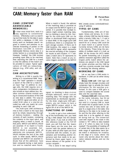
CAM ARCHITECTURE<br />
Writing to a CAM is exactly li ke<br />
writing to a conventional RAM. However,<br />
the “read” operation is actually<br />
a search of the CAM for a match to<br />
an input “tag.” In addition to storage<br />
cells, the CAM requires on e or<br />
more comparators Architectures can<br />
also include an input address bus. Another<br />
common scheme involves writing<br />
to consecutive locations of the CAM<br />
as new data is added. The outp uts<br />
are a MATCH signal and either an encoded<br />
N-bit value or a one-hot -encoded<br />
bus with one match bit corresponding<br />
to each CAM cell.<br />
The multi-cycle CAM architecture<br />
tries to find a match to the input data<br />
word by simply sequencing thro ugh<br />
all memory locations – reading the<br />
contents of each location, comparing<br />
the contents to the input valu e, and<br />
stopping when a match is found . At<br />
that point, MATCH and MATCH_VALID<br />
are asserted. If no match is f ound,<br />
MATCH is not asserted, but<br />
MATCH_VALID is asserted after all<br />
addresses are compared. MATCH_<br />
VALID indicates the end of the read<br />
cycle. In other words, MATCH_VALID<br />
asserted and MATCH not asserted indicate<br />
that all the addresses have<br />
been compared during a read operation<br />
and no matches were found .<br />
When a match is found, the address<br />
of the matching data is provid ed as<br />
an output and the MATCH signal is asserted.<br />
It is possible that multiple locations<br />
might contain matching data,<br />
but no checking is done for this. Storage<br />
for the multi-cycle CAM ca n be<br />
either in distributed RAM (registers)<br />
or block RAM. In the single-cycle CAM<br />
architecture, there is a comparator for<br />
each storage Location. If there are N<br />
CAM locations, the output is a single<br />
N-bit MATCH signal, which represents<br />
the one-hot encoding of the comparator<br />
results at each location. A ‘1’ indicates<br />
a match and a ‘0’ represents no<br />
match. Note that a match at an y location<br />
triggers assertion of the MATCH<br />
signal; no checking is done vis-à-vis<br />
multiple addresses, which cont ain<br />
matching data. The storage cells are<br />
implemented as distributed registers.<br />
For the Actel, single-cycle CAM generators,<br />
you can choose to hav e a<br />
single MATCH output, which is the<br />
logical OR of all of the MATCH bit.<br />
FUNCTIONS OF CAMS<br />
In order to get a true understanding<br />
of the functionality cam ,you need<br />
to dig a little deeper into the domain<br />
these works .if you look at either the<br />
OSI reference model or the TCP /IP<br />
stack ,you will find that the lowers<br />
three layers are the ones that are<br />
concern with the packet delive ry to<br />
its peer, while all other layers are more<br />
concerned with the content, its presentation<br />
and formatting another importance<br />
task that needs to be performed<br />
by these upper layers i s to<br />
ensure delivery of the packet to its<br />
correct recipient .<br />
This is done in two ways1-usin g<br />
Department of <strong>Electronics</strong> & Co mmunication<br />
Param Hans<br />
EC - III year<br />
MAC (media access control)address2-<br />
using IP address<br />
TYPES OF CAMS<br />
Fundamentally, CAMs are of two<br />
types: binary and ternary. As it indicates,<br />
a binary CAM has two bit states,<br />
while a ternary CAMs has 1, 0 and a<br />
third state called “don’t care .” So<br />
search-hit on a binary CAM could be<br />
an exact match or a parital ma tch.<br />
Currently ternary CAMs are de-facto<br />
in the industry. These bring the possibility<br />
of multiple match in a look up<br />
table. All the access list (ACI) tables<br />
for packet forwarding use a po pular<br />
address resolution algorithm called the<br />
longest prefix match where the addresses<br />
are placed in the CAM based<br />
on certain priorities and the CAM by<br />
itself has a priority encoder that helps<br />
in resolving the winning address.<br />
WORKING OF CAMS<br />
Let us see how a CAM works in<br />
hardware. A CAM can be either binary<br />
or ternary.<br />
Binary CAM cell: CAM logic will<br />
simply have the storage circuitary and<br />
comparator logic to provide the match<br />
information for the searches p erformed.<br />
In this case a XOR gat e is<br />
used to compare between the stored<br />
data and the searched data.<br />
Ternary CAM cell: A ternary CAM,<br />
as the name indicates, has thr ee<br />
states 0, 1, ‘X’. A don’t-care condition<br />
exist in a ternary CAM to mask<br />
off certain bits of partial match. In the<br />
context two sets of data world appear<br />
fo a single entry in the table. One<br />
referring to the data to be looked up<br />
for and the the other referring to the<br />
mask that is to be applied on every<br />
bit during look up. The conven tion<br />
used with respect to the mask in this<br />
context is “A’1’ refers to data masked<br />
and a ‘0’ refers to data not b eing<br />
masked”. The possibility of masking off<br />
of certain bits of the data opens up a<br />
wide range of applications were partial<br />
match is necessary for in stance,<br />
at the edge of a router, where the<br />
router only worries about the destination<br />
network address and not the<br />
host ID.<br />
18 <strong>Electronics</strong> <strong>Spectra</strong>, 2010