Sensoren - Lehrstuhls für Elektrische Antriebssysteme und ...
Sensoren - Lehrstuhls für Elektrische Antriebssysteme und ...
Sensoren - Lehrstuhls für Elektrische Antriebssysteme und ...

Create successful ePaper yourself
Turn your PDF publications into a flip-book with our unique Google optimized e-Paper software.
Technische Universität München<br />
Vorlesung<br />
„<strong>Elektrische</strong> Aktoren <strong>und</strong> <strong>Sensoren</strong> in geregelten Antrieben“<br />
„<strong>Sensoren</strong>“<br />
Prof. Dr.‐Ing. Ralph Kennel<br />
(ralph.kennel@tum.de)<br />
<strong>Elektrische</strong> <strong>Antriebssysteme</strong> <strong>und</strong> Leistungselektronik
Technische Universität München<br />
Vorlesung<br />
„<strong>Elektrische</strong> Aktoren <strong>und</strong> <strong>Sensoren</strong> in geregelten Antrieben“<br />
„<strong>Sensoren</strong>“<br />
Temperatursensoren
Pt100<br />
• Pt100-<strong>Sensoren</strong> sind Temperaturfühler,<br />
die auf der Widerstandsänderung von Platin<br />
unter Temperatureinfluss basieren.<br />
• Es handelt sich um Widerstandsthermometer, <strong>und</strong> zwar um Kaltleiter (PTC).<br />
• Pt100 (R 0= 100 Ohm)<br />
• Pt200 (R 0= 200 Ohm)<br />
• Pt500 (R 0= 500 Ohm)<br />
• Pt1000 (R 0= 1 kOhm)<br />
• die Widerstandsänderung ist in DIN EN 60751 (2009-05) festgelegt.<br />
• Standardisierung � leichte Austauschbarkeit der Temperaturfühler<br />
ohne Neukalibrierung<br />
• Pt100 genauer als Thermoelemente.
Bauformen des Pt100
European Standards -marking and Directives<br />
EU Directive<br />
• European Directive ‘safety of machines’<br />
• safe insulation<br />
• safe emergency stop<br />
• safe standstill without energy switch-off<br />
(e.g. double channel supervision)<br />
• safe limitation of motion<br />
� European Directive ‘low voltage’<br />
• safety against electrical shock<br />
� European Directive ‘EMC’<br />
• low harmonics in the mains<br />
• new product standard EN 61800-3 (IEC 1800-3)
mains<br />
EN 60204<br />
2000 V<br />
EN 61800-3<br />
1 300 V<br />
2 000 V ss<br />
ss<br />
VDE 0100<br />
400 V~<br />
VDE 0551<br />
3 750 v~<br />
overvoltage category I : VDE 0110<br />
Controller<br />
pulse voltage L --> L up = 750 V<br />
L --> PE up = 1500 V<br />
Isolation voltage L --> PE U = 800 V~<br />
test voltage L --> PE U = 640 V~<br />
Isolation Requirements<br />
VDE 0884<br />
xxx V~<br />
2 500 V~ 2 500 V~<br />
750 V=<br />
400 V~<br />
4 000 V ss<br />
DC link motor cable<br />
Capacitor<br />
VDE 0551<br />
3 750 v~<br />
Controller<br />
1 / 0 1 / 0<br />
overvoltage category II : VDE 0110<br />
pulse voltage L --> L up = 1200 V<br />
L --> PE up = 2500 V<br />
Isolation voltage L --> PE U = 1400 V~<br />
test voltage L --> PE U = 1200 V~<br />
VDE 0884<br />
xxx V~<br />
2 500 V~ 2 500 V~<br />
750 V=<br />
400 V~<br />
4 000 V ss<br />
2 500 V~<br />
temp.<br />
sensor<br />
overvoltage category III : VDE 0110<br />
pulse voltage L --> L up = 2000 V<br />
L --> PE up = 4000 V<br />
Isolation voltage L --> PE U = 2200 V~<br />
test voltage L --> PE U = 1800 V~
Technische Universität München<br />
Vorlesung<br />
„<strong>Elektrische</strong> Aktoren <strong>und</strong> <strong>Sensoren</strong> in geregelten Antrieben“<br />
„<strong>Sensoren</strong>“<br />
Stromsensoren
Ohne Feldsensor<br />
Strommessung Technik<br />
Shunt<br />
Rogowskispule<br />
Stromwandler<br />
magnetische<br />
Kopplung<br />
Strommessung<br />
Faraday-Effect<br />
Magnetwiderstand<br />
Hall-Effekt<br />
Magnetostriktion<br />
Technische Universität Warschau - Elektrotechnik<br />
mit Feldsensor<br />
8
Widerstand Strommessung<br />
Spannungsabfall<br />
Im<br />
• Spannungsabfall V auf dem bekannten Shunt R<br />
• der höhere Widerstand R, die höhere Spannung V<br />
Nachteile<br />
• Widerstand Anschluss in der Stromleiterbahn<br />
R<br />
• Keine Galvanische Trennung<br />
V<br />
Technische Universität Warschau - Elektrotechnik<br />
9
Current sensing with shunts (IR)<br />
low cost, low power solution with all drawbacks of shunts<br />
Quelle : Prof. Dr. -Ing. J. M. Pacas, Universität Siegen
Shunt measurement<br />
• precision resistors for current sensing should have:<br />
• a low temperature coefficient,<br />
• a low thermal EMF,<br />
• a high long-term stability,<br />
• a low inductance and<br />
• a high (pulse) load capacity.<br />
• these features are defined by selection of the resistance alloys,<br />
while properties are mainly determined by the construction.<br />
Quelle : Prof. Dr. -Ing. J. M. Pacas, Universität Siegen
Sensor Module (Isabellen Hütte)<br />
The ISA-ASIC, a combination of CMOS-ASIC and high precision shunt,<br />
basically is a low noise chopper stabilized 16 bit data acquisition system<br />
for extremely low input signals and therefore convenient for a lot of applications.<br />
Quelle : Prof. Dr. -Ing. J. M. Pacas, Universität Siegen
Hall-Effect<br />
• Halleffekt tritt im Leiter- oder in Halbleitermaterialien<br />
auf<br />
• Lineares Ausgangssignal<br />
• Unterschiedliche Empfindlichkeit <strong>und</strong> Bandbreite<br />
abhängig von Material<br />
• DC Stromkomponente kann gemessen werden<br />
• Stromquelle muss stabil sein<br />
Technische Universität Warschau - Elektrotechnik<br />
13
VH<br />
Hall-effect - Hallsensor<br />
B d<br />
IS<br />
Hall Platte<br />
Technische Universität Warschau - Elektrotechnik<br />
V � H<br />
I<br />
S<br />
B<br />
ned<br />
I s – Stromquelle <strong>für</strong> Hall-element<br />
d – Hall-element Dicke<br />
e – Elektronenladung<br />
n – Beweglicheladungen Dichte<br />
B – magnetische Induktion<br />
14
<strong>Sensoren</strong> ohne Rückkopplung<br />
• Unkompliziert<br />
• Fest<br />
(+)<br />
(-)<br />
• Niedrige Präzision (genügend <strong>für</strong><br />
bestimmte Systeme)<br />
• Nichtlinear<br />
• Temperaturempfindlich<br />
• Feldsensor muss weit<br />
Meßbereich haben<br />
Technische Universität Warschau - Elektrotechnik<br />
15
Z1<br />
I1<br />
Ф=-Ф0<br />
I2<br />
d0<br />
R<br />
I2<br />
Z2<br />
Ф<br />
VOUT<br />
<strong>Sensoren</strong> mit Rückkopplung<br />
Ф0<br />
Hallsensor<br />
I2<br />
Amp<br />
+Vc<br />
-Vc<br />
Ausgleichsspule<br />
Ф0<br />
Ф<br />
- Ausgleichs<br />
Magnetfluss<br />
- Magnetfluss<br />
von I1<br />
Technische Universität Warschau - Elektrotechnik<br />
(+)<br />
• Kompensation durch rückgekoppelten<br />
Strom<br />
• Sensor kann niedrig Meβbereiche<br />
haben<br />
• Temperaturkompensation<br />
• Strom- oder Spannungsausgangssignal<br />
• Bessere Linearität<br />
• höhere Präzision als <strong>Sensoren</strong> ohne<br />
Rückkopplung<br />
(-)<br />
• Probleme mit Ausgleich der hohen<br />
Ströme – hohe Induktivität der Spule<br />
• braucht bipolare Energieversorgung<br />
16
The MagnetoResistive (MR) Effect<br />
Magneto resistive sensor<br />
In thin films of permalloy (FE-Ni) material, the electrical<br />
resistance changes when an external magnetic field is applied in<br />
the plane of the film. The change is due to the rotation of the film<br />
magnetization. The variation of the resistance due an external<br />
field is called the anisotropic magnetoresistive (AMR) effect.<br />
Quelle : Prof. Dr. -Ing. J. M. Pacas, Universität Siegen<br />
Current Measurement<br />
The operating principle of by MRSensors<br />
current sensors is based on a differential<br />
field measurement with compensation.<br />
The primary current is fed through a<br />
conductor, creating a field gradient Hprim<br />
between the two sides of the conductor.<br />
The thin film magnetoresistive resistors<br />
are placed on a silicon chip and are<br />
connected in a Wheatstone bridge. The<br />
chip is mounted together with the<br />
analogue interface electronics on a single<br />
in-line hybrid circuit. In order to obtain a<br />
high linearity (0.1%) and a low<br />
temperature sensitivity, a current I S is fed<br />
back to the sensor chip through a<br />
compensation conductor located above<br />
the magnetoresistive resistors. The<br />
resulting field Hcomp exactly<br />
compensates Hprim, so that the sensor<br />
always works aro<strong>und</strong> a single point. At<br />
the output of the sensors, the<br />
compensation current flows.
different current measurements on drives<br />
Quelle : Prof. Dr. -Ing. J. M. Pacas, Universität Siegen
overcurrent conditions and their likely causes.<br />
Overcurrent Due to<br />
Line-to-line short<br />
Gro<strong>und</strong> fault<br />
Miswiring, motor leads<br />
short, phase-to-phase<br />
insulation breakdown<br />
Motor insulation<br />
breakdown to gro<strong>und</strong><br />
Shoot through Misfiring of IGBTs<br />
Quelle : Prof. Dr. -Ing. J. M. Pacas, Universität Siegen
Failure in one leg<br />
Quelle : Prof. Dr. -Ing. J. M. Pacas, Universität Siegen
Protection with one sensor<br />
Low cost solution but vector control and<br />
earth current protection are not possible!<br />
Quelle : Prof. Dr. -Ing. J. M. Pacas, Universität Siegen
Earth current<br />
Quelle : Prof. Dr. -Ing. J. M. Pacas, Universität Siegen
L1<br />
L2<br />
L3 L2<br />
Current measurement on DC-link<br />
Sensor for max<br />
current control<br />
Sensor for earth<br />
current protection<br />
earth current protection can be carried out<br />
with an additional sensor<br />
Quelle : Prof. Dr. -Ing. J. M. Pacas, Universität Siegen
�<br />
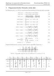
Rogowski Coil<br />
H� ds � w �i<br />
for a coil with … wird n turns inper<br />
length<br />
the flux linkage is determined by:<br />
Standard-Industrieantrieben<br />
d�nicht � � �eingesetzt A� n �H �ds<br />
0<br />
� � � �A �n �H �ds �<br />
� … also 0 wozu ???<br />
� � � A � n � w �i<br />
0<br />
�<br />
…wäre nützlich <strong>für</strong><br />
geberlose � �0 � A � n �Regelung � H �ds �<br />
von Asynchronmaschinen<br />
For the induced voltage results:<br />
� … spätere Präsentation<br />
d� di<br />
u � � �0 �A �n � w �<br />
dt dt<br />
Quelle : Prof. Dr. -Ing. J. M. Pacas, Universität Siegen
Technische Universität München<br />
Vorlesung<br />
„<strong>Elektrische</strong> Aktoren <strong>und</strong> <strong>Sensoren</strong> in geregelten Antrieben“<br />
„<strong>Sensoren</strong>“<br />
Drehzahl-/Positionssensoren<br />
… nächste Präsentation !!!
Fragen ?