110 / 210 Fiber Optic Oxygen Monitor - Instech Laboratories, Inc.
110 / 210 Fiber Optic Oxygen Monitor - Instech Laboratories, Inc.
110 / 210 Fiber Optic Oxygen Monitor - Instech Laboratories, Inc.

Create successful ePaper yourself
Turn your PDF publications into a flip-book with our unique Google optimized e-Paper software.
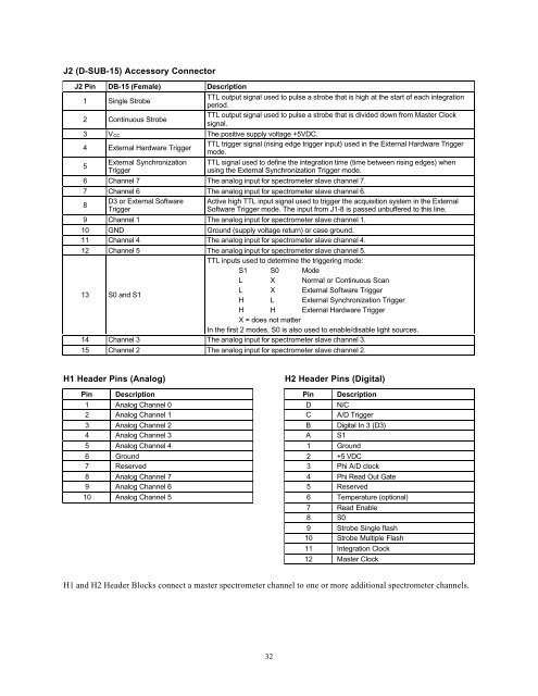
J2 (D-SUB-15) Accessory Connector<br />
J2 Pin DB-15 (Female) Description<br />
1 Single Strobe<br />
TTL output signal used to pulse a strobe that is high at the start of each integration<br />
period.<br />
2 Continuous Strobe<br />
TTL output signal used to pulse a strobe that is divided down from Master Clock<br />
signal.<br />
3 V CC The positive supply voltage +5VDC.<br />
4 External Hardware Trigger<br />
TTL trigger signal (rising edge trigger input) used in the External Hardware Trigger<br />
mode.<br />
5<br />
External Synchronization<br />
Trigger<br />
TTL signal used to define the integration time (time between rising edges) when<br />
using the External Synchronization Trigger mode.<br />
6 Channel 7 The analog input for spectrometer slave channel 7.<br />
7 Channel 6 The analog input for spectrometer slave channel 6.<br />
8<br />
D3 or External Software Active high TTL input signal used to trigger the acquisition system in the External<br />
Trigger<br />
Software Trigger mode. The input from J1-8 is passed unbuffered to this line.<br />
9 Channel 1 The analog input for spectrometer slave channel 1.<br />
10 GND Ground (supply voltage return) or case ground.<br />
11 Channel 4 The analog input for spectrometer slave channel 4.<br />
12 Channel 5 The analog input for spectrometer slave channel 5.<br />
TTL inputs used to determine the triggering mode:<br />
S1 S0 Mode<br />
L X Normal or Continuous Scan<br />
13 S0 and S1<br />
L X External Software Trigger<br />
H L External Synchronization Trigger<br />
H H External Hardware Trigger<br />
X = does not matter<br />
In the first 2 modes, S0 is also used to enable/disable light sources.<br />
14 Channel 3 The analog input for spectrometer slave channel 3.<br />
15 Channel 2 The analog input for spectrometer slave channel 2.<br />
H1 Header Pins (Analog)<br />
H2 Header Pins (Digital)<br />
Pin Description Pin Description<br />
1 Analog Channel 0 D N/C<br />
2 Analog Channel 1 C A/D Trigger<br />
3 Analog Channel 2 B Digital In 3 (D3)<br />
4 Analog Channel 3 A S1<br />
5 Analog Channel 4 1 Ground<br />
6 Ground 2 +5 VDC<br />
7 Reserved 3 Phi A/D clock<br />
8 Analog Channel 7 4 Phi Read Out Gate<br />
9 Analog Channel 6 5 Reserved<br />
10 Analog Channel 5 6 Temperature (optional)<br />
7 Read Enable<br />
8 S0<br />
9 Strobe Single flash<br />
10 Strobe Multiple Flash<br />
11 Integration Clock<br />
12 Master Clock<br />
H1 and H2 Header Blocks connect a master spectrometer channel to one or more additional spectrometer channels.<br />
32