Instruction Manual - GME
Instruction Manual - GME
Instruction Manual - GME

You also want an ePaper? Increase the reach of your titles
YUMPU automatically turns print PDFs into web optimized ePapers that Google loves.
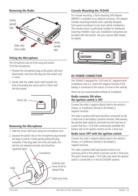
Removing the Radio<br />
Gently<br />
spread<br />
tabs<br />
UHF RADIO<br />
Slide radio<br />
from cradle<br />
Gently<br />
spread<br />
tabs<br />
Console Mounting the TX3440<br />
For console mounting, a flush mounting DIN Adaptor<br />
MBD001 is available as an optional accessory. The adaptor<br />
includes mounting brackets and a specially designed<br />
front panel escutcheon to suit most vehicle installations.<br />
The console mount is particularly suitable for dashboard<br />
mounting TX3440’s main unit. Installation instructions are<br />
provided with the bracket. See your nearest <strong>GME</strong> retailer<br />
for details.<br />
Fitting the Microphone<br />
The microphone uses an 8 pin plug and socket.<br />
To fit the microphone:<br />
1. Position the microphone plug so the plastic tab faces<br />
downwards, and press the plug into the socket until<br />
it ‘clicks’.<br />
2. Gently slide the rubber strain relief towards the<br />
hole surrounding the socket until it is flush with<br />
the front panel.<br />
Removing the Microphone<br />
1. Slide the strain relief back along the microphone cord.<br />
2. Squeeze the plastic tab on the microphone plug towards<br />
the plug to unlock it while gently pulling the plug<br />
outwards. If the plug does not come out easily, the<br />
tab has not released correctly and should be<br />
squeezed again.<br />
Cable<br />
Plastic tab<br />
Screwdriver<br />
Locking Lever<br />
move to left to<br />
release Plug<br />
UHF RADIO<br />
DC POWER CONNECTION<br />
The TX3440 is designed for 13.8 Volts DC, negative earth<br />
installations only (i.e. where the negative terminal of the<br />
battery is connected to the chassis or frame of the vehicle).<br />
There are two recommended methods of installation.<br />
Radio remains ON when<br />
the ignition switch is OFF<br />
Connect the radio's negative (black) lead to the vehicle's<br />
chassis, or if preferred, directly to the battery's<br />
negative terminal.<br />
The radio's positive (red) lead should be connected via the<br />
2 Amp fuse to the battery's positive terminal. Alternatively,<br />
the positive lead could be connected into the fuse box at<br />
a point that has +13.8 Volts continuously available (the<br />
battery side of the ignition switch) via the 2 Amp fuse.<br />
Radio turns OFF with the ignition switch:<br />
Connect the radio's negative (black) lead to the vehicle's<br />
chassis, or if preferred, directly to the battery's<br />
negative terminal.<br />
The radio's positive (red) lead should connect to an<br />
accessory point in the vehicle's fuse box via the 2 Amp fuse.<br />
This point should supply +13.8 Volts only when the ignition<br />
switch is turned ON or in the ACCESSORY position.<br />
Cable entry hole<br />
T X 3 4 4 0 i n s t r u c t i o n m a n ua l PA G E 1 9