Model Deluxe 62 - Bulldog Security
Model Deluxe 62 - Bulldog Security
Model Deluxe 62 - Bulldog Security

Create successful ePaper yourself
Turn your PDF publications into a flip-book with our unique Google optimized e-Paper software.
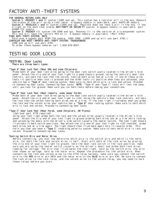
FACTORY ANTI-THEFT SYSTEMS<br />
FOR GENERAL MOTORS CARS ONLY<br />
System 1: PASSKEY I and II system (1985 and up). This system has a resistor pill in the key. Measure<br />
resistance of the pill using a test meter. A bypass module is available, part #VATS-WR module.<br />
System 2: PASSLOCK I and II system (1995 and up). Passlock does not have a pill in the key. It has<br />
a light on the dash that states ANTITHEFT OR SECURITY system. A bypass module is available, part<br />
#GMBP-721 module.<br />
System 3: PASSKEY III system (GM 1998 and up). Passkey III is GMs version of a transponder system.<br />
This key will have the letters PK3 on it. A bypass module is available. (Part #781)<br />
FORD ANTI-THEFT SYSTEM: PATS<br />
Ford uses a bypass part #FBP-718 module, 1995-1998. (1999 and up will use part #781.)<br />
CHRYSLER AND MOST IMPORTS ANTI-THEFT SYSTEM: TRANSPONDER<br />
1998 and up will use part #781.<br />
To order these bypass modules call 1-800-878-8007.<br />
TESTING DOOR LOCKS<br />
TESTING: Door Locks<br />
There are three basic types:<br />
“Type A” Door Lock Test (Most GMs and some Chryslers)<br />
Probe both of your door lock wires going to the door lock switch usally located in the driver’s kick<br />
panel. Attach the clip end of your test light to a good chassis ground. Using the vehicle’s door lock<br />
controls, activate the lock then the unlock, testing both wires one at a time. If one of these wires<br />
tests (+) positive when lock is pressed and the other tests (+) positive when they are unlocked, your<br />
vehicle has a “Type A” door locking system. Make sure to mark which wire is lock and unlock. Proceed<br />
to Connecting Door Locks, Connecting Door Locks. NOTE: “Type A” and “Type C” locks will test the same,<br />
until you test for ground. Make sure you run both tests before making your connections.<br />
“Type B” Door Lock Test (Most Imports, some newer Fords)<br />
Probe both of your door lock wires going to the door lock switch usally located in the driver’s kick<br />
panel. Attach the clip end of your test light to +12V. Using the vehicle’s door lock controls, activate<br />
the lock then the unlock testing both wires one at a time. If the test light illuminates when you probe<br />
the lock and the unlock wires your vehicle has a “Type B” door locking system. Make sure to mark which<br />
wire is lock and unlock. Proceed to Connecting Door Locks.<br />
“Type C” Door Lock Test (Most Fords, some Chryslers, GM Trucks)<br />
(Optional part #778 required)<br />
Using your test light probe both the lock and the unlock wires usually located in the driver’s kick<br />
panel. Attach the clip end of your test light to ground probing both wires one at a time while locking<br />
and unlocking the doors with the driver’s side switch (usually the master switch). The test light should<br />
illuminate in both switch positions. Now attach the clip end of your test light to +12V constant, probe<br />
both wires one at a time again. The light should then illuminate again only in reverse order. This<br />
tells you that you have a “Type C” reversing polarity system. Make sure to mark which wire is lock and<br />
unlock. Proceed to Connecting Door Locks.<br />
Testing Switch Wire and Motor Wires<br />
Before connecting, you must now determine which wire is the switch wire and which is the motor<br />
wire. Cut both the lock and unlock wires in half. Start with both of the lock wires by placing<br />
the clip end of your test light to ground, hold the door lock switch in the lock position, make<br />
sure you are using the master switch (usually on the driver’s door) and probe both lock wires<br />
looking for voltage. The wire that illuminates the test light, mark as the switch wire, the wire<br />
that shows no voltage, mark as the motor wire. Repeat the procedure for the unlock wire. When<br />
connecting the lock and unlock wires to the #778 relay harness, make sure you connect the switch<br />
wire to the RED wire or pin #87A and the motor wire to the BLUE wire or pin #30. Be sure to connect<br />
the lock wires to the lock relay, and the unlock wires to the unlock relay, you may need to mark<br />
these relays before you start.<br />
9