Model Deluxe 62 - Bulldog Security
Model Deluxe 62 - Bulldog Security
Model Deluxe 62 - Bulldog Security

You also want an ePaper? Increase the reach of your titles
YUMPU automatically turns print PDFs into web optimized ePapers that Google loves.
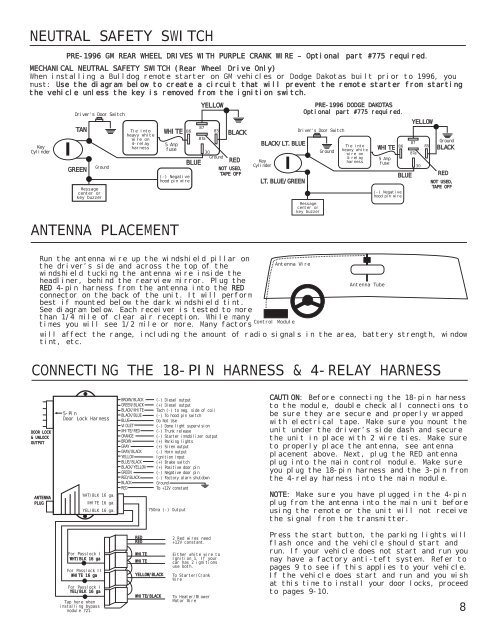
NEUTRAL SAFETY SWITCH<br />
PRE-1996 GM REAR WHEEL DRIVES WITH PURPLE CRANK WIRE – Optional part #775 required.<br />
MECHANICAL NEUTRAL SAFETY SWITCH (Rear Wheel Drive Only)<br />
When installing a <strong>Bulldog</strong> remote starter on GM vehicles or Dodge Dakotas built prior to 1996, you<br />
must: Use the diagram below to create a circuit that will prevent the remote starter from starting<br />
the vehicle unless the key is removed from the ignition switch.<br />
Key<br />
Cylinder<br />
Driver’s Door Switch<br />
TAN<br />
GREEN<br />
Ground<br />
Message<br />
center or<br />
key buzzer<br />
Tie into<br />
heavy white<br />
wire on<br />
4-relay<br />
harness<br />
WHITE<br />
5 Amp<br />
fuse<br />
ANTENNA PLACEMENT<br />
86<br />
(-) Negative<br />
hood pin wire<br />
BLUE<br />
YELLOW<br />
87<br />
87a<br />
85<br />
30<br />
Ground<br />
BLACK<br />
RED<br />
NOT USED,<br />
TAPE OFF<br />
BLACK/LT.BLUE<br />
Key<br />
Cylinder<br />
LT.BLUE/GREEN<br />
PRE-1996 DODGE DAKOTAS<br />
Optional part #775 required.<br />
Driver’s Door Switch<br />
Message<br />
center or<br />
key buzzer<br />
Ground<br />
Tie into<br />
heavy white<br />
wire on<br />
4-relay<br />
harness<br />
WHITE<br />
5 Amp<br />
fuse<br />
86<br />
(-) Negative<br />
hood pin wire<br />
BLUE<br />
YELLOW<br />
87<br />
87a<br />
30<br />
85<br />
Ground<br />
BLACK<br />
RED<br />
NOT USED,<br />
TAPE OFF<br />
Run the antenna wire up the windshield pillar on<br />
Antenna Wire<br />
the driver’s side and across the top of the<br />
windshield tucking the antenna wire inside the<br />
headliner, behind the rearview mirror. Plug the<br />
Antenna Tube<br />
RED 4-pin harness from the antenna into the RED<br />
connector on the back of the unit. It will perform<br />
best if mounted below the dark windshield tint.<br />
See diagram below. Each receiver is tested to more<br />
than 1/4 mile of clear air reception. While many<br />
Control Module<br />
times you will see 1/2 mile or more. Many factors<br />
will affect the range, including the amount of radio signals in the area, battery strength, window<br />
tint, etc.<br />
CONNECTING THE 18-PIN HARNESS & 4-RELAY HARNESS<br />
DOOR LOCK<br />
& UNLOCK<br />
OUTPUT<br />
ANTENNA<br />
PLUG<br />
5-Pin<br />
Door Lock Harness<br />
WHT/BLK 16 ga.<br />
WHITE 16 ga.<br />
YEL/BLK 16 ga.<br />
BROWN/BLACK<br />
GREEN/BLACK<br />
BLACK/WHITE<br />
BLACK/BLUE<br />
BLUE<br />
VIOLET<br />
WHITE/RED<br />
ORANGE<br />
BROWN<br />
GRAY<br />
GRAY/BLACK<br />
YELLOW<br />
BLUE/BLACK<br />
BLACK/YELLOW<br />
GREEN<br />
RED/BLACK<br />
BLACK<br />
RED<br />
(-) Diesel output<br />
(+) Diesel output<br />
Tach (-) to neg. side of coil<br />
(-) To hood pin switch<br />
Do Not Use<br />
(-) Dome light supervision<br />
(-) Trunk release<br />
(-) Starter immobilizer output<br />
(+) Parking lights<br />
(+) Siren output<br />
(-) Horn output<br />
Ignition input<br />
(+) Brake switch<br />
(+) Positive door pin<br />
(-) Negative door pin<br />
(-) Factory alarm shutdown<br />
Ground<br />
To +12V constant<br />
750ma (-) Output<br />
CAUTION: Before connecting the 18-pin harness<br />
to the module, double check all connections to<br />
be sure they are secure and properly wrapped<br />
with electrical tape. Make sure you mount the<br />
unit under the driver’s side dash and secure<br />
the unit in place with 2 wire ties. Make sure<br />
to properly place the antenna, see antenna<br />
placement above. Next, plug the RED antenna<br />
plug into the main control module. Make sure<br />
you plug the 18-pin harness and the 3-pin from<br />
the 4-relay harness into the main module.<br />
NOTE: Make sure you have plugged in the 4-pin<br />
plug from the antenna into the main unit before<br />
using the remote or the unit will not receive<br />
the signal from the transmitter.<br />
For Passlock I<br />
WHT/BLK 16 ga<br />
For Passlock II<br />
WHITE 16 ga<br />
For Passlock I<br />
YEL/BLK 16 ga<br />
Tap here when<br />
installing bypass<br />
module 721.<br />
RED<br />
RED<br />
WHITE<br />
WHITE<br />
YELLOW/BLACK<br />
WHITE/BLACK<br />
2 Red wires need<br />
+12V constant.<br />
Either white wire to<br />
Ignition 1. If your<br />
car has 2 ignitions<br />
use both.<br />
To Starter/Crank<br />
Wire<br />
To Heater/Blower<br />
Motor Wire<br />
Press the start button, the parking lights will<br />
flash once and the vehicle should start and<br />
run. If your vehicle does not start and run you<br />
may have a factory anti-teft system. Refer to<br />
pages 9 to see if this applies to your vehicle.<br />
If the vehicle does start and run and you wish<br />
at this time to install your door locks, proceed<br />
to pages 9-10.<br />
8