Model Deluxe 62 - Bulldog Security
Model Deluxe 62 - Bulldog Security
Model Deluxe 62 - Bulldog Security

Create successful ePaper yourself
Turn your PDF publications into a flip-book with our unique Google optimized e-Paper software.
HOOD PIN SWITCH<br />
This feature will keep the engine from starting or shut off the engine when the hood is opened.<br />
Locate a good chassis ground, if at all possible do not install the pin switch in the rain gutter.<br />
Drill a 5/16 hole, insert the pin switch into the hole and tighten. Check for the hood adjustment,<br />
there is approximately 1/4” adjustment in the pin switch. Close the hood easy, making sure that<br />
the pin switch is not keeping the hood from closing all the way, if it does, cut off approximately<br />
1/8” of the black plastic off of the top of the hoodpin switch and try closing the hood again.<br />
Check to make sure that the hoodpin switch remains neutral when the hood is closed and shows ground<br />
when the hood is open. Plug the BLACK WITH BLUE STRIPE wire from the 18-pin harness into the bottom<br />
of the hood pin switch.<br />
TACH INPUT (Optional) (Must use with diesel engines)<br />
By this time, you should have determined the way you want your vehicle to start (tach or tachless).<br />
If you have chosen the TACHLESS start option, simply proceed to the next step and skip the following<br />
instructions. Make sure this wire is taped up when not used. For TACH mode connect the BLACK WITH<br />
WHITE STRIPE wire from the 18-pin harness to the negative side of the coil or the tach wire at<br />
the coil pack under the hood. To find the coil pack follow the spark plug wires back to the<br />
termination point. To operate in tach mode, make sure to program tach option, see programming<br />
tach option page 11.<br />
DOOR PIN TRIGGER<br />
To determine if your door pin is turned on with (+) positive or (-) negative trigger, probe for a<br />
wire in the driver’s side kick panel that switches polarity when the door is closed then opened.<br />
You can also find this wire going to the under dash courtesy lights.<br />
•If this wire reads +12V when the door is open and (-) ground when the door is closed, it is (+)<br />
positive. (most Fords)<br />
•If this wire reads (-) ground when the door is open and +12V when the door is closed,<br />
it is (-) negative.<br />
If your vehicle is a (+) positive door pin connect the BLACK WITH WITH YELLOW STRIPE wire from<br />
the 18-pin harness to the door pin wire. If your vehicle is a (-) negative door pin, connect the<br />
GREEN wire from the 18-pin harness to the door pin wire. Make sure you tape up the unused wire.<br />
NOTE: When testing the door pin wire, make sure the dome light is on. Some vehicles, if the door<br />
is left open for a period of time, the dome light will go out, resulting in a false reading.<br />
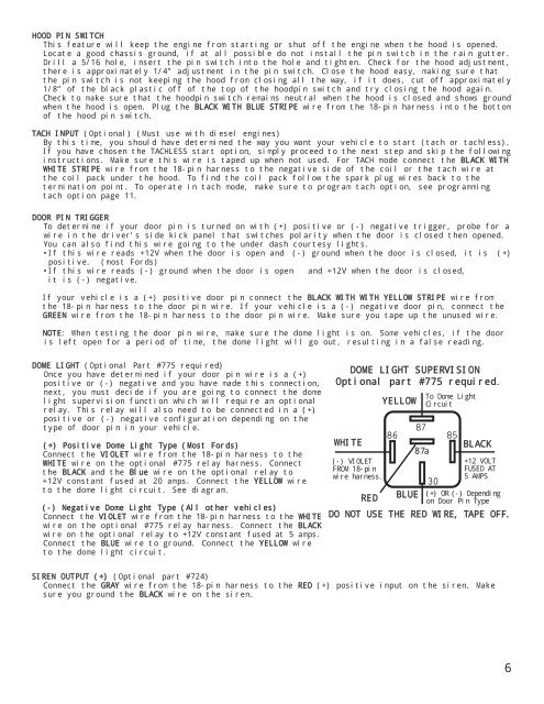
DOME LIGHT (Optional Part #775 required)<br />
Once you have determined if your door pin wire is a (+)<br />
positive or (-) negative and you have made this connection,<br />
next, you must decide if you are going to connect the dome<br />
light supervision function which will require an optional<br />
relay. This relay will also need to be connected in a (+)<br />
positive or (-) negative configuration depending on the<br />
type of door pin in your vehicle.<br />
(+) Positive Dome Light Type (Most Fords)<br />
Connect the VIOLET wire from the 18-pin harness to the<br />
WHITE wire on the optional #775 relay harness. Connect<br />
the BLACK and the Blue wire on the optional relay to<br />
+12V constant fused at 20 amps. Connect the YELLOW wire<br />
to the dome light circuit. See diagram.<br />
(-) Negative Dome Light Type (All other vehicles)<br />
Connect the VIOLET wire from the 18-pin harness to the WHITE<br />
wire on the optional #775 relay harness. Connect the BLACK<br />
wire on the optional relay to +12V constant fused at 5 amps.<br />
Connect the BLUE wire to ground. Connect the YELLOW wire<br />
to the dome light circuit.<br />
DOME LIGHT SUPERVISION<br />
Optional part #775 required.<br />
WHITE<br />
(-) VIOLET<br />
FROM 18-pin<br />
wire harness.<br />
RED<br />
YELLOW<br />
BLUE<br />
87a<br />
To Dome Light<br />
Circuit<br />
BLACK<br />
+12 VOLT<br />
FUSED AT<br />
5 AMPS<br />
(+) OR (-) Depending<br />
on Door Pin Type<br />
DO NOT USE THE RED WIRE, TAPE OFF.<br />
SIREN OUTPUT (+) (Optional part #724)<br />
Connect the GRAY wire from the 18-pin harness to the RED (+) positive input on the siren. Make<br />
sure you ground the BLACK wire on the siren.<br />
6