
You also want an ePaper? Increase the reach of your titles
YUMPU automatically turns print PDFs into web optimized ePapers that Google loves.
MARCH <strong>1997</strong><br />
16-50053-101<br />
FINAL<br />
NBA'<br />
FASTBREAK<br />
The manufacturer intends that this game is to be operated for<br />
amusement purposes only and not in contravention of any<br />
federal, state or local law or regulation of the United States or<br />
any foreign country governing gaming devices. All operators<br />
of this game are responsible for its operation in accordance<br />
<strong>with</strong> such laws and regulations. The manufacturer’s factory<br />
settings for this game may require adjustment in order to<br />
comply <strong>with</strong> laws applicable in an operator’s specific<br />
jurisdiction. It is the operator’s responsibility to determine<br />
whether adjustments are necessary and, if they are, to make<br />
the appropriate adjustments prior to operating the<br />
amusement game.<br />
C €<br />
OPERATIONS MANUAL INCLUDES<br />
Operations & Adjustments • Testing & Problem Diagnosis • Parts Information • Wiring<br />
Diagrams & Schematics<br />
Williams Electronics Games, Inc., 3401 N. California Avenue, Chicago, IL 60618
DIP SWITCH SETTINGS AND JUMPERS<br />
EPROM Jumper Settings for G11________ W1__________W2<br />
1 1MEG, 2MEG, 4 MEG EPROM In Out<br />
DIP Switch Chart<br />
COUNTRY SW1 SW2 SW3 SW4 SW5 SW6 SW7 SW8<br />
AMERICA Off Off On On On On On On<br />
EUROPEAN Off Off On On On Off On On<br />
FRENCH Off Off On On On On Off Off<br />
GERMAN Off Off On On On On On Off<br />
SPAIN Off Off On On Off On On On<br />
SOLENOID/FLASH ER TABLE<br />
Sol.<br />
Function<br />
Solenoid Voltage Connections Drive Drive Connections Drive Solenoid Part Number<br />
No.<br />
Type<br />
Xistor<br />
Wire Flashlam p Type<br />
Playfield Backbox Cabinet<br />
Playfield Backbox Cabinet Color Playfield Backbox<br />
01 AUTO PLUNGER High Power J133-2 Q72 J 116-1 VIO-BRN AE-24-900<br />
02 NOT USED High Power 068 VIO-RED<br />
03 LEFT RAMP DIVERTER High Power J 133-2 071 J 116-4 VIO-ORG AE-26-1500<br />
04 RIGHT LOOP DIVERTER High Power J 133-2 067 J116-5 VIO-YEL AE-26-1500<br />
05 EJECT High Power J 133-2 Q70 J116-6 VIO-GRN AE-30-2000<br />
06 LOOP GATE High Power J 133-2 066 J116-7 VIO-BLU A-14406<br />
07 BACKBOX FLIPPER High Power J 133-2 069 J117-3 VIO-BLK FL-11753<br />
08 BALL CATCH MAGNET High Power J 133-2 065 J116-9 VIO-GRY B-13522<br />
09 TROUGH EJECT Low Power J 133-3 044 J113-1 BRN-BLK AE-28-1500<br />
10 LEFT SLINGSHOT Low Power J 133-3 048 J113-3 BRN-RED AE-26-1200<br />
11 RIGHT SLINGSHOT Low Power J 133-3 Q43 J113-4 BRN-ORG AE-26-1200<br />
12 LEFT JET BUMPER Low Power J133-3 047 J113-5 BRN-YEL AE-26-1200<br />
13 MIDDLE JET BUMPER Low Power J 133-3 Q42 J 113-6 BRN-GRN AE-26-1200<br />
14 RIGHT JET BUMPER Low Power J 133-3 Q46 J113-7 BRN-BLU AE-26-1200<br />
15 PASS RIGHT 2 Low Power J133-3 Q41 J 113-8 BRN-VIO AE-29-2000<br />
16 PASS LEFT 2 Low Power J133-3 Q45 J113-9 BRN-GRY AE-29-2000<br />
17 EJECT KICKOUT FLSHR Flasher J 133-6 Q28 J111-1 BLK-BRN #906 (1)<br />
18 LEFT JET BUMPER FLSHR Flasher J 133-6 032 J111-2 BLK-RED #906 (1)<br />
19 UPPER LEFT FLASHER Flasher J 133-6 J134-5 027 J111-3 J112-3 BLK-ORG #906 (1) #906 (1)<br />
20 UPPER RIGHT FLASHER Flasher J 133-6 J134-5 031 J 111-4 J 112-5 BLK-YEL # 906 (1) #906 (1)<br />
21 NOT USED Flasher 026 BLU-GRN<br />
22 TROPHY INSERT FLSHR Flasher J 133-6 030 J111-6 BLU-BLK #906 (1)<br />
23 NOT USED Flasher 025 BLU-VIO<br />
24 LOWER RIGHT/LEFT FLSH Flasher J 133-6 029 J111-8 BLU-GRY #906 (2)<br />
25 •PASS RIGHT 1 Gen. Purpose J 133-1 016 J 109-1 BLU-BRN AE-29-2000<br />
26 •PASS LEFT 3 Gen. Purpose J133-1 015 J 109-2 BLU-RED AE-29-2000<br />
27 •PASS RIGHT 3 Gen. Purpose J133-1 Q14 J 109-3 BLU-ORG AE-29-2000<br />
28 •PASS LEFT 4 Gen. Purpose J 133-1 013 J 109-4 BLU-YEL AE-29-2000<br />
Ge neral Illum ination<br />
01 STRING 1 G.l. J106-1 J 105-1 0 5 J 106-7 J 105-7 WHT-BRN #44 #555<br />
02 STRING 2 G.l. J 106-2 J105-2 04 J 106-8 J 105-8 WHT-ORG #44 #555<br />
03 STRING 3 G.l. J 106-3 J 105-3 03 J 106-9 J 105-9 WHT-YEL #44 #555<br />
04 "STRING 4 G.l. J 106-5 02 J106-10 WHT-GRN #44<br />
05 "STRING 5 G.l J 106-6 J 105-6 J 104-3 Q1 J106-11 J105-11 J104-1 WHT-VIO #44 #555<br />
Voltage<br />
Drive<br />
Solenoid Connection Drive Xistors Connections Drive W ire Colors Coil Coil<br />
FI pper Circuits<br />
Type<br />
Playfield Power Hold Playfield Power Hold Part No. Colors<br />
29<br />
Lwr Rt. Power J119-1 (RED-GRN) 090 J 120-13 Y'EL-GRN FL-11630 RED<br />
30 LOWER RIGHT FLIPPER Lwr. Rt. Hold J119-1 (RED-GRN) Q92 J120-11 ORG-GRN<br />
31<br />
Lwr. Lt. Power J119-4 (RED-BLU) Q87 J 120-9 rEL-BLU FL-11630 RED<br />
32 LOWER LEFT FLIPPER Lwr. Lt. Hold J119-4 (RED-BLU) Q89 J 120-7 ORG-BLU<br />
33 SHOOT 1 Upr. Rt. Power J119-6 (RED-VIO) Q84 J 120-6 /EL-VIO AE-23-800<br />
34 SHOOT 2 Upr. Rt. Hold J119-6 (RED-VIO) Q86 J 120-4 ORG-VIO AE-23-800<br />
35 SHOOT 3 Upr. Lt. Power J119-8 (RED-GRY) 081 J 120-3 V'EL-GRY AE-23-800<br />
36 SHOOT 4 Upr. Lt. Hold J119-8 (RED-GRY) 083 J 120-1 ORG-GRY AE-23-800<br />
Voltage<br />
Drive<br />
Solenoid Connections Drive Drive Connections Wire Device Part Number<br />
Me tor & Shot Clock Circuits<br />
Type Playfield Gates Playfield Color<br />
Playfield<br />
37 MOTOR ENABLE Low Power J 139-2 U3A, U3B J110-1 BRN-WHT 14-8034<br />
38 MOTOR DIRECTION Low Power J 139-2 U3C, U3D J110-3 ORG-WHT 14-8034<br />
39 SHOT CLOCK ENABLE Low Power J 139-2 U3G, U3H J110-4 YEL-WHT A-21380<br />
40 SHOT CLOCK COUNT Low Power J 139-2 U3E, U3F J 110-5 BLU-WHT A-21380<br />
J1XX = POWER DRIVER BOARD<br />
24-6549 = #44 BULB; 24-8704 = #89 BULB; 24-8768 = #555 BULB; 24-8802 = #906 BULB<br />
•TIEBACK DIODES FOR SOLENOIDS 25 THROUGH 28 ARE AT J109-5, J109-6, J109-8, AND J109-9 RESPECTIVELY.<br />
"THESE G.l. STRINGS DO NOT BRIGHTEN AND DIM, THEY ARE ALWAYS ON.
DECLARATION OF CONFORMITY<br />
WILLIAMS ELECTRONICS GAMES INC.<br />
3401 N. CALIFORNIA AVE.<br />
CHICAGO, IL 60618<br />
U.S.A.<br />
WE, HEREBY DECLARE UNDER SOLE RESPONSIBILITY THAT<br />
THE MODEL: "NBA FAST BREAK" 50253 50353,50453,50753,50953,<br />
51053,51153,51353,51453,51853,52053,52153,52253,52353,57253 PINBALL<br />
to Which t h is d e c l a r a t io n r e l a t e s is in confo rm ity With t h e<br />
FOLLOWING EUROPEAN PRODUCT SAFETY DIRECTIVES:<br />
ELECTROMAGNETIC COMPATABILITY DIRECTIVE<br />
(89/336/EEC AND AMENDMENTS 91/C l62/08, 92/31/EEC,93/68/EEC<br />
ELECTRICAL EQUIPMENT DESIGNED FOR USE WITHIN<br />
CERTAIN VOLTAGE LIMITS DIRECTIVE<br />
(73/23/EEC AND AMENDMENTS 88/C168/02, 92/C210/01,<br />
93/68/EEC, 94/C 199/03, 95/C214/02)<br />
i<br />
EN 55014:1993 EN55104:1995 EN61000-4-2: 1995<br />
IEC 801-3: 1984 (EN61000-4-3 ) EN61000-4-4: 1995 EN61000-4-5: 1995<br />
ENV50141: 1993 (EN61000-4-6 ) EN61000-4-11: 1994 EN60335-1: 1995<br />
IEC 335-2-82 (DRAFT)<br />
Date issued: JANUARY 1,<strong>1997</strong><br />
MANUFACTURE'S SIGNATURE<br />
DANGALARDE<br />
CORPORATE V.P. OF QUALITY
ATTENTION<br />
The game uses a Security CPU Board that is not downward compatible to the<br />
CPU boards used in previous games. The board has an added security chip that<br />
can be interchanged between other NBA® FASTBREAK games and software<br />
revision levels. The CPU board itself is interchangeable <strong>with</strong> later model games,<br />
but must be equipped <strong>with</strong> the correct security chip and software for that specific<br />
game.<br />
The games’ electronic ID number is shown in the display during power-up. The<br />
number displayed is the same nine digit number printed on the security chip<br />
label. The first three digits are the project number <strong>with</strong>out the country specific<br />
code. An example of the power-up display is shown below, the electronic ID<br />
number is bolded.<br />
TESTING<br />
50053 EPROM 1.0 A<br />
553 100006 95749
IMPORTANT NOTICE<br />
PLEASE READ<br />
This pinball game is equipped <strong>with</strong> a SAFETY FEATURE to prevent shocks from<br />
the solenoid circuit when the coin door is opened. An interlock switch assembly<br />
(part no. A-18249-3), located at the left of the coin door opening, has been<br />
added to the game. This assembly is a bracket containing the existing memory<br />
protect switch on the bottom and a new interlock switch on the top. When the<br />
coin door is opened, this new interlock switch opens, breaking the connection to<br />
the +50V and +20V winding of the transformer secondary.<br />
A - 1 8 2 4 9 - 3 )<br />
[ A - 1 8 2 4 9 -2 , JAPAN ONLY)
NBA<br />
FASTBREAIC<br />
The information is current as of the time of its release.<br />
Fill out and mail in game Registration card. Be sure to include the game serial number. For your<br />
records, write the PIC and game serial numbers in manual.<br />
PIC Number ____________________<br />
Serial Number ____________________<br />
Williams Electronics Games, Inc. reserves the rights to make modifications and improvements to<br />
its products. The specifications and parts identified in this manual are subject to change <strong>with</strong>out<br />
notice.
TABLE OF CONTENTS<br />
P la y fie ld S h o ts a n d G a m e R u le s ...............................................................................................I<br />
S e c tio n 1 - G a m e O p e ra tio n & T e s t In fo r m a tio n ............................................................. 1-1<br />
(System WPC) ROM Summary............................................................................................. 1-1<br />
Pinball Game Assembly Instructions..................................................................................... 1-2<br />
Marquee Installation Instructions.............................................................................................1-6<br />
Game Control Locations.......................................................................................................... 1-8<br />
Game Operation...................................................................................................................... 1-9<br />
Raising the Playfield................................................................................................................ 1-10<br />
Menu System Operation and Main Menu.............................................................................. 1-11<br />
Bookkeeping Menu..................................................................................................... 1-12<br />
B.1 Main Audits....................................................................................................... 1-12<br />
B.2 Earnings Audits............................................................................................... 1-12<br />
B.3 Standard Audits............................................................................................... 1-12<br />
B.4 Feature Audits.................................................................................................. 1-13<br />
B.5 Histograms....................................................................................................... 1-15<br />
B.6 Time-Stamps.................................................................................................... 1-16<br />
Printouts Menu............................................................................................................ 1-17<br />
Test Menu......................................................................................................................1-18<br />
T.1 Switch Edges Test........................................................................................... 1-18<br />
T.2 Switch Levels Test........................................................................................... 1-18<br />
T.3 Single Switch Test........................................................................................... 1-18<br />
T.4 Solenoid Test....................................................................................................1-19<br />
T.5 Flasher Test......................................................................................................1-19<br />
T.6 G.l. Test............................................................................................................ 1-19<br />
T.7 Sound and Music Test.....................................................................................1-20<br />
T.8 Single Lamp Test............................................................................................. 1-20<br />
T.9 All Lamps Test..................................................................................................1-20<br />
T. 10 Lamp and Flasher Test..................................................................................1-20<br />
T.11 Display Test....................................................................................................1-20<br />
T.12 Flipper Coil Test............................................................................................. 1-21<br />
T.13 Ordered Lamp Test........................................................................................1-21<br />
T.14 Lamp Row-Col................................................................................................1-21<br />
T.15 DIP Switch Test............................................................................................. 1-21<br />
T.16 Motor Test.......................................................................................................1-21<br />
T.17 Backbox Test................................................................................................. 1-22<br />
T.18 Empty Balls Test............................................................................................ 1-22<br />
Utilities Menu............................................................................................................... 1-23<br />
U.1 Clear Audits......................................................................................................1-23<br />
U.2 Clear Coins.......................................................................................................1-23<br />
U.3 Reset H.S.T.D.................................................................................................. 1-23<br />
U.4 Set Time & Date.............................................................................................. 1-23<br />
U.5 Custom Messages........................................................................................... 1-23<br />
U.6 Set Game I.D....................................................................................................1-23<br />
Copyright <strong>1997</strong> Williams Electronics Games, Inc.
Section 1 Continued...<br />
U.7 Factory Adjustment......................................................................................... 1-24<br />
U.8 Factory Reset...................................................................................................1-24<br />
U.9 Presets.............................................................................................................. 1-24<br />
Game Difficulty Table for U.S., Canadian, French, German,<br />
and European Games..................................................................................... 1-24<br />
Preset Table for U.S./Canada........................................................................ 1-24<br />
U. 10 Clear Credits.................................................................................................. 1-26<br />
U.11 Auto Burn-in................................................................................................... 1-26<br />
Adjustments Menu...................................................................................................... 1-27<br />
A.1 Standard Adjustments.....................................................................................1-27<br />
A.2 Feature Adjustments....................................................................................... 1-31<br />
A.3 Pricing Adjustments......................................................................................... 1-38<br />
Pricing Table..................................................................................................... 1-46<br />
A.4 H.S.T.D. Adjustment........................................................................................ 1-47<br />
A.5 Printer Adjustments......................................................................................... 1-48<br />
Error Messages.........................................................................................................................1-49<br />
CPU Board & Audio Visual Board Error Codes.......................................................... 1-50<br />
Opto Theory.................................................................................................................... 1-51<br />
LED List..................................................................................................................................... 1-52<br />
Fuse List.................................................................................................................................... 1-53<br />
Maintenance Information........................................................................................................ 1-54<br />
S e c tio n 2 - G a m e P a rts In fo r m a tio n .......................................................................................2-1<br />
Backbox Assembly................................................................................................................... 2-2<br />
Cabinet Assembly.................................................................................................................... 2-3<br />
Backbox Insert.......................................................................................................................... 2-4<br />
Audio Visual Board Assembly.................................................................................................2-6<br />
Power Driver Board Assembly................................................................................................2-8<br />
CPU Security Board................................................................................................................. 2-10<br />
Coin Door Interface Board Assembly..................................................................................... 2-12<br />
Flipper Opto Board Assembly.................................................................................................2-12<br />
Trough LED Board Assembly................................................................................................. 2-13<br />
2-LED Driver Board Assembly.................................................................................................2-13<br />
Opto 24-Switch Board Assembly............................................................................................ 2-14<br />
High Current Driver Board Assembly..................................................................................... 2-15<br />
2-Digit LED Assembly...............................................................................................................2-15<br />
7-Switch Opto Board Assembly..............................................................................................2-16<br />
Trough Photo Transistor Board Assembly............................................................................. 2-16<br />
Flipper Assembly.......................................................................................................................2-17<br />
Ball Trough Assembly Complete.............................................................................................2-20<br />
Kicker Arm (slingshot) Assembly........................................................................................... 2-21<br />
Jet Bumper Assemblies.......................................................................................................... 2-22<br />
Jet Bumper Coil Assembly...................................................................................................... 2-23<br />
Jet Coil & Bracket Assembly................................................................................................... 2-23<br />
Pass Assembly - No. 1.............................................................................................................2-24
Section 2 Continued-<br />
Pass Assembly - No. 2.............................................................................................................2-25<br />
Pass Assembly - No. 3.............................................................................................................2-25<br />
Pass Assembly - No. 4.............................................................................................................2-26<br />
Auto-Fire Assembly..................................................................................................................2-27<br />
Defender Arm Assembly...........................................................................................................2-28<br />
Back Board Assembly............................................................................................................. 2-29<br />
Magnet Assembly..................................................................................................................... 2-30<br />
Ball Gate Actuator Assembly...................................................................................................2-30<br />
Loop Diverter Assembly........................................................................................................... 2-31<br />
Hook Diverter Assembly.......................................................................................................... 2-31<br />
Tilt Mechanism Assembly........................................................................................................ 2-32<br />
Knocker Assembly.................................................................................................................... 2-32<br />
Basket Switch Assembly......................................................................................................... 2-33<br />
Basket Assembly.......................................................................................................................2-33<br />
Eject Assembly.......................................................................................................................... 2-33<br />
Power Interface Assembly...................................................................................................... 2-34<br />
Power Interface/Cordset Application...................................................................................... 2-35<br />
Upper Playfield Parts List........................................................................................................ 2-36<br />
Upper Playfield Parts Locations..............................................................................................2-37<br />
Lower Playfield Parts List........................................................................................................ 2-38<br />
Lower Playfield Parts Locations..............................................................................................2-39<br />
Solenoid/Flashlamp Locations List.........................................................................................2-40<br />
Solenoid/Flashlamp Locations.................................................................................................2-41<br />
Switch Locations List................................................................................................................ 2-42<br />
Switch Locations...................................................................................................................... 2-43<br />
Lamp Locations List................................................................................................................. 2-44<br />
Lamp Locations.........................................................................................................................2-45<br />
Solenoid/Flashlamp Table....................................................................................................... 2-46<br />
Lamp Matrix.............................................................................................................................. 2-47<br />
Switch Matrix.............................................................................................................................2-48<br />
S e c tio n 3 - W irin g D ia g ra m s & S c h e m a tic s .......................................................................3-1<br />
Connector & Component Identification..................................................................................3-1<br />
Switch Matrix and Switch Matrix Circuit.................................................................................3-2<br />
Dedicated Switch Circuit......................................................................................................... 3-3<br />
Lamp Matrix and Lamp Matrix Circuit....................................................................................3-4<br />
Solenoid/Flashlamp Circuit Table.......................................................................................... 3-5<br />
Solenoid Wiring........................................................................................................................ 3-6<br />
Flashlamp Wiring..................................................................................................................... 3-7<br />
High Power and Low Power Solenoid Circuits......................................................................3-8<br />
Flashlamp and Special (General Purpose) Solenoid Circuits............................................. 3-9<br />
General Illumination Circuit..................................................................................................... 3-10<br />
Flipper Circuit Diagram............................................................................................................3-11<br />
Flipper Coil and End-of-Stroke Circuits..................................................................................3-12<br />
Flipper Cabinet Switch Circuits...............................................................................................3-13<br />
¡V
Section 3 Continued...<br />
Flipper Opto Board Assembly................................................................................................. 3-14<br />
Trough IR LED Board Assembly.............................................................................................3-15<br />
Trough IR Photo Transistor Board Assembly....................................................................... 3-16<br />
Ball Trough Opto Switches Wiring Diagram.......................................................................... 3-17<br />
Center Ramp Opto and Right Loop Enter Opto Switches Wiring Diagram........................ 3-17<br />
7-opto Switch Board Assembly...............................................................................................3-18<br />
7-opto Switch Board Schematic..............................................................................................3-19<br />
24-opto Switch Board Assembly.............................................................................................3-20<br />
24-opto Switch Board Schematic........................................................................................... 3-21<br />
LED and Photo Transistor Board Assemblies....................................................................... 3-22<br />
Defender Switch Board Assembly......................................................................................... 3-23<br />
2 LED Driver Board Assembly................................................................................................ 3-24<br />
2 LED Display Board Assembly..............................................................................................3-25<br />
High Current Driver Board Assembly..................................................................................... 3-26<br />
Security CPU Board Interboard Wiring List........................................................................... 3-27<br />
Audio Visual Board Interboard Wiring List............................................................................. 3-28<br />
Power Driver Board Interboard Wiring List........................................................................... 3-29<br />
Coin Door Interface Board Interboard Wiring List.................................................................3-32<br />
Coin Door Interface Board Schematic................................................................................... 3-33<br />
V
NOTES
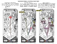
PLAYFIELD SHOTS<br />
AND<br />
GAME RULES
PLAYFIELD SHOTS<br />
COMPLETING SHOTS RROM<br />
ALL FOUR SHOOTER<br />
POSTTIONS STARTS<br />
•AROUND THE WORLD<br />
MULTBALLV<br />
SHOOTER 1 POSmON<br />
SHOOTER 4 POSITION<br />
SHOOTER 2 POSmON<br />
SHOOTER 3 POSmON<br />
UGHT POWER HOOPS<br />
JET BUMPERS HTTS<br />
ADVANCE THRU<br />
HOOP MODES<br />
COMPLETE ®© © < D<br />
TO START ’SHOOT<br />
AROUND MULTBALL*.<br />
N THE PAINT.<br />
EXTRA BALL<br />
LIGHT ALLEY OOP<br />
IN THE PAINT<br />
UGHT INBOUND PASS<br />
LIGHT TIP-OFF<br />
LIGHT INBOUND PASS<br />
PIZZA POWER POINTS<br />
(START BACK BOX<br />
GAME)<br />
LIGHT<br />
•IN THE PAINT<br />
CHAMPIONSHIP<br />
RINGS<br />
(To earn ringa,<br />
win Trophy multibal )<br />
LIGHT<br />
•IN THE PANT<br />
INBOUND PASS<br />
(EARNED BALL SAVE)<br />
SHOOT AROUND<br />
MULTIBALL<br />
AROUND THE<br />
WORLD MULTIBALL<br />
USE FLIPPERS<br />
TO PASS WHEN<br />
N THE PAINT. -<br />
USE FLIPPERS<br />
TO PASS WHEN<br />
IN THE PAINT.
NBA® FASTBREAK RULES<br />
TEAM SELECTION:<br />
When a game is started, the player is prompted on the dot matrix display to select their team. The player<br />
can use the flippers to cycle through the 29 NBA teams. When the SHOOT button is pressed to launch<br />
the ball, the selected team is locked in place. Each team has an associated current high score. If the<br />
player beats that score during their game, they will be asked to enter their initials and their score will<br />
replace the current high score for that team.<br />
SCORING:<br />
Scores are representative of a basketball game. Each basket shot during normal play scores 1, 2, or 3<br />
points depending on the situation. During modes, other non-basket shots may cause a backbox basket to<br />
be shot for 1, 2, or 3 points. In addition to points, good players will also collect "CHAMPIONSHIP<br />
RINGS". One ring is collected each time all six of the main goals are completed and the player plays and<br />
wins the "TROPHY MULTIBALL" round. In terms of score comparisons, rings are more significant than<br />
points (e.g. 1 ring 100 points beats 0 rings 150 points).<br />
GOAL OF THE GAME:<br />
Compete for the high score for each of the 29 NBA team champions. Complete the six main goals (listed<br />
below) to play "TROPHY MULTIBALL". Win at "TROPHY MULTIBALL" to collect "CHAMPIONSHIP<br />
RINGS" and to be the Most Valuable Player (M.V.P.).<br />
NBA TEAM CHAMPIONS:<br />
Each player competes to better the current high score for the NBA team they select. If the player's score<br />
beats the current team score, then the player's initials and score will replace the current high score the<br />
selected NBA team. Rings are included in determining winning scores. See "SCORING" above.<br />
CHAMPIONSHIP RINGS:<br />
One "CHAMPIONSHIP RING" is awarded each time the player wins during "TROPHY MULTIBALL". See<br />
"TROPHY MULTIBALL" below for further details.<br />
M.V.P.:<br />
The Most Valuable Player is the last player to complete the six main goals and to win "TROPHY<br />
MULTIBALL". The initials of the current M.V.P. are shown during attract mode and during game play on<br />
the dot matrix display.<br />
THE SIX MAIN GOALS:<br />
There are six main goals of the game that must be completed in order to play "TROPHY MULTIBALL".<br />
Each goal is completed by the criteria listed below:<br />
1. "20 POINTS" complete<br />
2. "MULTIBALLS" complete<br />
3. "FIELD GOALS" complete<br />
4. "COMBINATION SHOTS" complete<br />
5. "POWER HOOPS" complete<br />
6. "STADIUM GOODIES" complete<br />
20 POINTS:<br />
Once 20 points are achieved through any means of game play, the "20 POINTS" complete lamp is lit.
MULTIBALLS:<br />
Once the two primary multiballs (listed below) are played out, the "MULTIBALLS" complete lamp is lit.<br />
1. "SHOOT AROUND"<br />
2. "AROUND THE WORLD"<br />
FIELD GOALS:<br />
Once the three types of "FIELD GOAL" (listed below) are made, the "FIELD GOALS" complete lamp is lit.<br />
Most baskets award a two-point field goal. A three-point field goal is awarded for a shot to the basket<br />
<strong>with</strong> the "3 POINT" lamp lit, as well as during certain modes. A one -oint field goal is awarded for a shot<br />
to the basket <strong>with</strong> the "FREE THROW" lamp lit.<br />
1. "FREE THROW"<br />
2. “2 POINT"<br />
3. "3 POINT"<br />
COMBINATION SHOTS:<br />
Once the four types of combination shots (listed below) are made, the "COMBINATION SHOTS"<br />
complete lamp is lit. Each combination shot is made by making the "LIGHT (TIP-OFF, SLAM DUNK,<br />
ALLEY OOP, FASTBREAK}" shot followed quickly by the "{TIP-OFF, SLAM DUNK, ALLEY OOP,<br />
FASTBREAK}" shot to the basket.<br />
1. "TIP-OFF"<br />
2. "SLAM DUNK"<br />
3. "ALLEY OOP"<br />
4. "FASTBREAK"<br />
POWER HOOPS:<br />
Once the four "POWER HOOPS“ modes (listed below) are played, the "POWER HOOPS" complete lamp<br />
is lit. Power hoops are started from "JET BUMPER" hits. The modes are explained in greater detail<br />
below.<br />
1. "HALF COURT HOOPS”<br />
2. “HOOK SHOT HOOPS”<br />
3. "RUN & SHOOT HOOPS"<br />
4. "HOOPS MULTIBALL"<br />
STADIUM GOODIES:<br />
Once the four "STADIUM GOODIES" items (listed below) have been collected, the "STADIUM<br />
GOODIES" complete lamp is lit. Visiting “CRAZY BOB’S” vendor stand collects stadium goodies (the<br />
LEFT EJECT).<br />
1. PIZZA POWER SHOTS<br />
2. HOT DOG MANIA<br />
3. TRIVIA QUIZ<br />
4. EGYPTIAN SODA<br />
PIZZA POWER SHOTS:<br />
The first of the "STADIUM GOODIES", this mode is played entirely in the backbox and on the dot matrix<br />
display. Each time the player hits a flipper (or pushes the SHOOT button), the backbox flips the ball<br />
towards the backbox basket. If the ball goes through the hoop, the player scores the point value on the<br />
dot matrix display. The point value cycles between 1, 2, and 3 points. The mode is over when the SHOT<br />
CLOCK expires.<br />
IV
HOT DOG MANIA:<br />
The second of the "STADIUM GOODIES", during this mode, all shots made by the player cause the<br />
backbox to flip for a 3 point basket. In addition to points, the SHOT CLOCK time is reset to 24 each time a<br />
shot is made. The mode is over when the SHOT CLOCK expires.<br />
TRIVIA QUIZ:<br />
The third of the "STADIUM GOODIES", this mode is played entirely on the dot matrix display. The player<br />
is presented <strong>with</strong> a randomly selected question and four answers. The flippers cycle through the<br />
answers. If the selected answer is correct, the player is awarded 10 points. If the selected answer is<br />
wrong, the player is awarded 1 point. The mode is over when either the SHOT CLOCK expires, or the<br />
SHOOT button is pressed.<br />
EGYPTIAN SODA:<br />
Egyptian Soda is the fourth and final "STADIUM GOODIES" mode. During this mode, each ramp shot<br />
made by the player cause the backbox to flip for a three-point basket. The mode is over when the SHOT<br />
CLOCK expires.<br />
IN THE PAINT:<br />
This is the area below the top lanes, under the basket. There are four positions where the ball can be<br />
held in the ring around the basket. Each of the four positions can either pass or shoot the ball. There is<br />
also a defensive player which moves between any position and the basket to block the player's shot to<br />
the basket. If the player shoots either the left or right loop when "IN THE PAINT" is lit, the SHOT CLOCK<br />
is set to 24 seconds and begins counting down. The player must pass the ball to a position that is not<br />
defended and attempt to shoot a basket for 2 points, before the shot clock expires. Making a basket from<br />
a position lights the lamp at that position. If the shot clock expires before a basket is made, the ball is<br />
automatically passed out of the area and returned to normal play. Completing all of the lamps (making a<br />
basket from each position) starts "AROUND THE WORLD" multiball.<br />
AROUND THE WORLD MULTIBALL:<br />
This three-ball multiball is started when a shot is made from each of the four "IN THE PAINT" positions.<br />
During this multiball, one of the five main shots is lit. The shot moves either when it is made or after a<br />
short period of time. Making the lit shot scores one point for each ball remaining in play.<br />
SHOOT SPELL OUT:<br />
The letters 'S', 'H', 'O', 'O', and T are located one per playfield shot. Making a shot lights the associated<br />
letter. Completing all of the letters starts "SHOOT AROUND" multiball.<br />
SHOOT AROUND MULTIBALL:<br />
This two-ball multiball is started when all of the "SHOOT" spell out letters are completed. During this<br />
multiball, the "SHOOT" letters start out blinking. Each time a letter is shot, two points are awarded and<br />
the letter is lit solid. Completing all of the letters starts them all blinking again and may light EXTRA<br />
BALL,<br />
3 PT SPELL OUT:<br />
The number and letters '3', 'P', and T are located in front of the three center playfield standup targets.<br />
Completing all three standup target lamps lights the "3 POINTS" lamp on both the left and center ramps.<br />
Making a basket by either the left or center ramp <strong>with</strong> the "3 POINTS" lamp lit awards a three-point field<br />
goal.<br />
V
TIP-OFF:<br />
This combination shot is lit both at the start of each ball or by making the right loop shot into the "JET<br />
BUMPERS" when "LIGHT TIP-OFF" is lit. Making the center ramp shot when "TIP-OFF" is lit completes<br />
the "TIP-OFF COMBINATION SHOT".<br />
SLAM DUNK:<br />
This combination shot is lit by making the right ramp shot when “LIGHT SLAM DUNK" is lit. Making the<br />
left ramp shot when "SLAM DUNK" is lit completes the "SLAM DUNK COMBINATION SHOT".<br />
ALLEY OOP:<br />
This combination shot is lit by making the left loop shot when "LIGHT ALLEY OOP" is lit. Making the<br />
center ramp shot when "ALLEY OOP" is lit completes the "ALLEY OOP COMBINATION SHOT".<br />
FASTBREAK:<br />
This combination shot is lit by making either the left or right ramp shots when "LIGHT FASTBREAK" is lit.<br />
Making the center ramp shot when "FASTBREAK" is lit completes the "FASTBREAK COMBINATION<br />
SHOT".<br />
HALF COURT HOOPS:<br />
This mode is started at the first “POWER HOOPS" level, achieved in the "JET BUMPERS". During this<br />
mode, the center ramp scores 3 points per shot. The mode is over when the SHOT CLOCK expires.<br />
HOOK SHOT HOOPS:<br />
This mode is started at the second "POWER HOOPS" level, achieved in the "JET BUMPERS". During<br />
this mode, the left ramp scores 3 points per shot. The mode is over when the SHOT CLOCK expires.<br />
RUN & SHOOT HOOPS:<br />
This mode is started at the third "POWER HOOPS" level, achieved in the "JET BUMPERS". During this<br />
mode, the left and center ramps are alternately lit and score 3 points when shot. The mode is over when<br />
the SHOT CLOCK expires.<br />
HOOPS MULTIBALL:<br />
This two- ball multiball is started at the fourth "POWER HOOPS" level. During this multiball, the left and<br />
right ramps are alternately lit and score 3 points when shot.<br />
HOOP LOOPS:<br />
If the left loop shot is made during any of the "POWER HOOPS" modes/multiball, “HOOP LOOPS" are<br />
tallied. When a certain auto-percentaged number of loops are completed, an EXTRA BALL may be lit.<br />
POWER POINTS:<br />
At various numbers of "JET BUMPER" hits, the backbox flips the ball for a "POWER POINTS" 2 point<br />
basket.<br />
VI
TROPHY MULTIBALL:<br />
This timed three-ball continuous multiball is started when the six main goals are completed. During this<br />
multiball, the player competes for approximately one minute to beat an artificial computer score. The<br />
multiball starts <strong>with</strong> the computer's score (shown on the right of the display) tied <strong>with</strong> the player's score<br />
(shown on the left - as usual). The computer's score escalates randomly over the timed period. The<br />
player's score increases as shots are made. Once the time expires (as shown on the 24 "second" SHOT<br />
CLOCK), the flippers are turned off and the balls are drained. If the player beats the computer, a<br />
"CHAMPIONSHIP RING" is awarded. If the player ties the computer, a short sudden death round is<br />
played where the player has a certain amount of time to score before the computer scores. The first to<br />
score wins. In either case (win or lose) all of the six main goals are reset, and play begins again, <strong>with</strong><br />
increased difficulty.<br />
EXTRA BALL:<br />
There are a number of ways to light the "EXTRA BALL" lamp. The first is to shoot the "FREE THROW"<br />
shot an auto-percentaged number of times. The second is to complete all of the jackpots (spell "SHOOT"<br />
during "SHOOT AROUND" multiball. The third is lit by completing all four "COMBINATION SHOTS". The<br />
fourth is by completing the auto-percentaged number of "HOOP LOOPS".<br />
LIGHT INBOUND PASS (right standups):<br />
Completing the right hand standup target lamps lights the left outlane "INBOUND PASS" lamp.<br />
INBOUND PASS (left outlane):<br />
This lamp is lit by completing the right hand standup targets. When the ball goes out the left outlane and<br />
"INBOUND PASS" is lit, a new ball is put back into play via the auto plunger and the player continues to<br />
play.<br />
MILLION DOLLARS SHOT (right outlane):<br />
This lamp is lit on the player's last ball, after the BALL SAVE lamp has expired. Draining out the right<br />
outlane when this lamp is lit gives the player a chance to continue playing by making the center ramp<br />
basket shot before the SHOT CLOCK expires.<br />
VII
NOTES
NOTES
NOTES<br />
X
SECTION ONE<br />
GAME OPERATION<br />
AND TEST INFORMATION<br />
(System WPC) ROM SUMMARY<br />
IC TYPE BOARD LOCATION PART NUMBER<br />
Game 1 27c040 CPU G11 A-5343-50053-1<br />
Security Chip PIC16C57 CPU G10 A-5400-50053-1<br />
Music/Speech M27c801 Audio SU2 A-5343-50053-S2<br />
Music/Speech M27c801 Audio SU3 A-5343-50053-S3<br />
Music/Speech M27c801 Audio SU4 A-5343-50053-S4<br />
Music/Speech M27c801 Audio SU5 A-5343-50053-S5<br />
Music/Speech M27C801 Audio SU6 A-5343-50053-S6<br />
NOTICE<br />
Order replacement ROMS from your authorized Williams Electronics Games, Inc. distributor. Specify<br />
(1), part number (if available); (2), ROM level (number) on label; (3) game in which ROM is used.<br />
1-1
PINBALL GAME ASSEMBLY INSTRUCTIONS<br />
NBA0 FASTBREAK IS A FOUR BALL GAME,<br />
Power:<br />
Temp:<br />
Humidity:<br />
Domestic 120V @ 60Hz<br />
Foreign 230V @ 50Hz<br />
Japan 100V @ 50HZ<br />
32°F to 100° F, (0°C to 38°C)<br />
Not to exceed 95% relative.<br />
Dimensions:<br />
Weight:<br />
Width: 29" approx.<br />
Depth: 52" approx.<br />
Height: 75" approx.<br />
325 lb. approx. (crated)<br />
1. Remove all cartons, parts, and other items from the shipping container and set them aside.<br />
2. Leg levelers and leg bolts are among the parts in the cash box. Install leg levelers on the front and<br />
rear legs (View 1). Place cabinet on a support and attach rear legs using leg bolts (View 2).<br />
3. Attach front legs using leg bolts (View 2).<br />
o<br />
t ) ( :<br />
:o:<br />
FRONT<br />
REAR<br />
VIEW 2<br />
4. Reach into the cabinet and backbox and ensure that the interconnecting cables are not kinked or<br />
pinched. Be careful to avoid damaging wires at any stage of the assembly process.<br />
1-2
5. Raise the hinged backbox upright and latch it into position.<br />
Note: The insert panel is no longer hinged to the backbox; it is attached to the backglass.<br />
backglass and the insert panel are removed from the backbox housing as a single unit.<br />
The<br />
Unlock the backbox. Carefully, lift the backglass/insert panel from the bottom and slide it out of the<br />
backbox. Lay it down on the playfield glass. Unplug the cable extending from the backbox to the<br />
insert panel. Carefully, set the backglass/insert panel aside.<br />
Note: The speaker panel uses a new hinging system. The bottom of the speaker panel remains<br />
attached to the backbox unit when released.<br />
Carefully lift the speakers panel so that the top notches clear the top pins. Rotate it away from the<br />
backbox, toward the playfield glass. The speaker panel will remain attached to the backbox unit.<br />
This allows access to the bolt holes for securing the backbox upright. Install the washer-head<br />
mounting bolts through the bottom holes of the backbox into the threaded fasteners in the cabinet<br />
to secure the backbox.<br />
Note: You have the option of removing the speaker panel completely. Lay the speaker panel on<br />
the playfield glass. Unplug the display cable, speaker cable, and ground strap. Line up the bottom<br />
notches <strong>with</strong> the bottom backbox pins. Lower the speaker panel through the notches and slide it<br />
under the backbox pins.<br />
6. After the washer-head mounting bolts are installed, replace the speaker panel and the<br />
backglass/insert panel. Lock the backbox.<br />
A CAUTION<br />
FAILURE TO INSTALL the backbox mounting hardware properly can cause personal injury.<br />
NEVER TRANSPORT a pinball game <strong>with</strong> the hinged backbox erect. Always lower the backbox<br />
forward onto the playfield cabinet on a layer of protective material to prevent marring or damage<br />
and possible personal injury.<br />
7. Extend each leg leveler slightly below the leg bottom, so that all four foot pads are extended about<br />
the same distance. Remove the cabinet from its support and place it on the floor.<br />
1-3
8. Unlock and open the coin door. Move the lever guide toward the left side of the game. Lift the front<br />
molding up and set it on the playfield glass. Carefully, unplug the Shoot button cable from the<br />
cabinet cable. Lift the front molding off of the game. Return the lever guide to the right, and close<br />
the coin door. Carefully slide the glass downward, until it clears the grooves of the left and right<br />
side moldings. Lift the glass up and away from the game, storing it carefully to avoid breakage.<br />
9. Place a level or an inclinometer on the playfield surface. Adjust the leg levelers for proper playfield<br />
level (side-to-side).<br />
Note: This measurement must be made ON the playfield, not the cabinet or the playfield cover<br />
glass. Tighten the nut on each leg leveler shaft to maintain this setting.<br />
10. The TRU-PITCH level is located on the right shooter rail. This allows the playfield pitch angle to<br />
be properly adjusted WITHOUT REMOVING THE GLASS. The first line (closest to the front of the<br />
game) on the level is approximately 6 degrees. Every line thereafter is approximately another 1/2<br />
degree of pitch. The recommended pitch is 6-1/2 degrees. The NOSE of the bubble should be<br />
between the first and second line on the level (see diagram below).<br />
TRU-PITCH level 6 - 1 / 2<br />
degrees.<br />
IMPORTANT!<br />
Playfield pitch angle can affect the operation of the plumb bob tilt. The plumb bob weight is among<br />
the parts in the cash box; the operator should install the weight and adjust this tilt mechanism for<br />
proper operation, after completion of the desired playfield pitch angle setting. The unit is factory<br />
installed for a 6-1/2 degree angle. If an adjustment is necessary, loosen the screw at the bottom of<br />
the unit. Move the pointer, one grove at a time to the left or the right, depending on the degree<br />
desired. Hold the pointer in place and tighten screw<br />
11. Be sure the required number of balls is installed. The NBA® FASTBREAK “ game uses FOUR<br />
balls.<br />
12. Install full playfield Mylar, if desired.<br />
Note: The NBA® FASTBREAK playfield is coated <strong>with</strong> a special hardcoat surface and does not<br />
require a protective Mylar. However, mylars can be purchased through your local Williams<br />
Distributor. Specify part number 03-9678-1 for full playfield Mylar.<br />
1-4
13. Clean and reinstall the playfield cover glass. Replace and lock the front molding.<br />
14. To attach the line cord, remove the four Phillips-head screws that mount to line cord cover plate to<br />
the rear cabinet. Match the prongs on the plug <strong>with</strong> the holes in the receptacle, and push the line<br />
cord securely into place. Make sure the cord is aligned <strong>with</strong> the indentation on the cover plate<br />
(indentation should point toward bottom of the cabinet). Remount line cord cover plate. If desired,<br />
four tamper resistant screws have been provided, in the unique parts bag, to remount cover plate.<br />
15. Move the game into the desired location; recheck the level and pitch angle of the playfield.<br />
16. If a padlock is desired, install the security bar as shown below.<br />
17 IMPORTANT: Fill out and return the registration card.<br />
1-5
MARQUEE INSTALLATION INSTRUCTIONS<br />
" ■" "" ■ | ' " ' ' rth TM<br />
The Marquee Kit is an option, made specifically for NBA Fastbreak , which can<br />
be purchased through your distributor. The part number for the NBA® Fastbreak<br />
Marquee Kit is 57964._________________________________________________________<br />
PARTS<br />
Part Number Description Quantity<br />
01-12569 brackets 6<br />
31-2822-1 right side panel (screened) 1<br />
31-2822-2 left side panel (screened) 1<br />
31-2823 top panel (screened) 1<br />
4108-01001-12 screws sms #8 x 3/4 p-ph-a 24<br />
LEFT SIDE PANEL<br />
RIGHT SIDE PANEL<br />
INSTALLATION<br />
1. Turn off and unplug the game.<br />
2. Install two brackets on the back of each panel.<br />
Start <strong>with</strong> the top panel. Look for the pinpricks in the back of the panel. Line up the screw holes in<br />
the brackets <strong>with</strong> the pinprick marks on the panel. The brackets are symmetrical, so it doesn’t matter<br />
which direction the flange faces. Use two of the screws, provided, to fasten each bracket to the<br />
panel. Repeat this same procedure for the left and right side panels.<br />
3. Install the panels onto the backbox.<br />
Again, start <strong>with</strong> the top panel. Line up the front edge of the top panel <strong>with</strong> the front edge of the<br />
backbox. Fasten the top panel to the top of the backbox <strong>with</strong> four of the screws, (two in each<br />
bracket).<br />
Next, install the right side panel. Line up the screw holes in the brackets <strong>with</strong> the crosshatch marks,<br />
(+) in backbox artwork. Be sure the brackets are flush against the side of the backbox. Fasten the<br />
right side panel to the backbox <strong>with</strong> four of the screws (two in each bracket). Repeat this same<br />
procedure for the left side panel.<br />
NOTE: The left and right side panels overlap the bottom of the top panel and the sides of the<br />
backbox. See drawings on the next page.<br />
1-6
1-7
GAME CONTROL LOCATIONS<br />
Cabinet Switches<br />
The On-Off Switch is on the bottom of the cabinet near the right front leg.<br />
The Start Button is a push-button to the left of the coin door on the cabinet exterior.<br />
button to begin a game, or during the diagnostic mode, to ask for HELP.<br />
Press the Start<br />
Coin Door Buttons<br />
The operator controls all game adjustments, obtains bookkeeping information, and diagnoses problems,<br />
using only four push-button switches mounted on the inside of the coin door. The coin door buttons have<br />
two modes of operation Normal Function and Test Function.<br />
Normal Function<br />
The Service Credits button puts credits on the games that are not included in any of the game audits.<br />
The Volume Up (+) button raises the sound level of the game. Press and hold the button until the<br />
desired level is reached.<br />
The Volume Down (-) button lowers the sound level of the game. Press and hold the button until the<br />
desired level is reached. See Adjustment A.1 28 to turn sound off completely.<br />
The Begin Test button starts the Menu System operation and changes the coin door buttons from<br />
Normal Function to Test Function.<br />
Test Function<br />
The Escape button allows you to get out of a menu selection or return to the Attract mode.<br />
The Up M button allows you to cycle forward through the menu selections or adjustment choices.<br />
The Down (-) button allows you to cycle backward through the menu selections or adjustment<br />
choices.<br />
The *Enter button allows you to get into a menu selection or lock in an adjustment choice.<br />
*To reset High Score, hold down the Begin Test/Enter switch for five seconds while in the Attract<br />
mode.<br />
1-8
A CAUTION<br />
GAME OPERATION<br />
After assembly and installation at its site location, this game must be plugged into a properly<br />
grounded outlet to prevent shock hazard, and to assure proper game operation. DO NOT use a<br />
'cheater' plug to defeat the ground pin on the line cord. DO NOT cut off the ground pin.<br />
POWERING UP. With the coin door closed, plug the game in, and switch it on. In normal operation,<br />
TESTING shows in the displays as the game performs Start-up tests. Once the Start-up tests have<br />
been successfully completed the last score is displayed and the game goes into the Attract mode.<br />
Note: After the game has been on location for a time, the Start-up tests may contain messages<br />
concerning game problems. See ‘Error Messages’ for more detailed information regarding messages.<br />
Open the coin door and press the Begin Test switch. The display shows the game name, number, and<br />
software revision. The message changes and the display will show the sound software revision, the<br />
revision level of the system software, and the date the software was revised.<br />
Example: NBA9 FASTBREAK Sound Rev. 1.0A<br />
50053 Rev. 1.0A SY. 0.X0 XX-XX-97<br />
Press the Enter button to enter the Menu System (refer to the section entitled "Menu System Operation"<br />
for more information). Perform the entire Test menu routine to verify that the game is operating<br />
satisfactorily.<br />
Note: In order to operate the tests that use the +50V or +20V circuits, pull the top interlock switch<br />
button out. The interlock switches are located on a bracket in the coin door opening.<br />
ATTRACT MODE*. After completing the Test menu routine, press the Escape button three times to enter<br />
the Attract mode. During the Attract mode, the display shows a series of messages informing the<br />
player of the recent highest 'scores, "‘ custom messages", and the score to obtain a replay *award.<br />
CREDIT POSTING. Insert coin(s). A sound is heard for each coin, and the display shows the number of<br />
credits purchased. So long as the number of maximum allowable credits* are NOT exceeded by coin<br />
purchase or high score, credits are posted correctly.<br />
STARTING A GAME. Press the Start button. A startup sound plays, and the credit amount shown in the<br />
display decreases by one. The display flashes 00 (until the first playfield switch is actuated), and shows<br />
ball 1. If credits are posted, additional players may enter the game by pressing the Start button once<br />
for each player, before the end of play on the first ball.<br />
TILTS. Actuating the cabinet tilt switch inside the cabinet ends the current game and proceeds to the<br />
Game Over mode. With the third closure* of the plumb bob tilt switch, the player loses the remaining<br />
play of that ball, but can complete the game.<br />
END OF A GAME. All earned scores and bonuses are awarded. If a player's final score exceeds the<br />
specified value, the player receives a designated award for achieving the current highest score. A<br />
random digit set* appears in the display. Credits* may be awarded, when the last two digits of any<br />
player's score match the random digits. Match, high score, and game over sounds are made.<br />
GAME OVER MODE. The Game Over display shows the high scores and the game proceeds to the<br />
Attract Mode.<br />
* - Operator-adjustable feature<br />
1-9
RAISING THE PLAYFIELD<br />
A CAUTION<br />
Do not raise the playfield straight up! This game uses a slide assembly to raise and lower the<br />
playfield.<br />
Before Raising the Playfield:<br />
Be sure there are no balls present in the ball trough or any of the other ball-holding playfield<br />
devices (i.e. poppers). Raising the playfield <strong>with</strong> balls present in these locations may cause them<br />
to come loose and damage the playfield. Use the "Empty Balls Test" to remove all of the balls<br />
from these locations.<br />
To Raise the Playfield.<br />
1. Grasp bottom arch and carefully lift up playfield only high<br />
enough to clear safety brackets. Rear guide legs should<br />
not hit wood guide rails, or be used to slide out playfield.<br />
2. Pull the playfield out toward you until it stops (rest position),<br />
and raise it approximately 3".<br />
Be sure playfield is in locked position and does not<br />
slide back into cabinet. If it does, repeat Step 2 before<br />
proceeding to Step 3.<br />
3. Rotate playfield to upright service position (lean on<br />
backbox) by pulling toward you and up. Listen for the<br />
sound of a click: this ensures locking and pivoting<br />
sequence.<br />
To Lower the Playfield.<br />
4. Rotate the playfield to the rest position. This unlocks the<br />
pivoting mechanism.<br />
' ** Slide Mecnomsm<br />
(2 used)<br />
5. Push the playfield back into cabinet and into the playing<br />
position.<br />
1-10
MENU SYSTEM OPERATION<br />
The Main Menu allows you to choose from several options, which in turn lead to other menus to choose<br />
from. To access the Main Menu open the coin door, press the Begin Test button, then the Enter button.<br />
Press the Up and Down buttons to scroll through the Main Menu. To access a menu, (Bookkeeping,<br />
Printouts, etc.), from the Main Menu, press the Enter button. To return to the Main Menu (from<br />
Bookkeeping, Printouts, etc.) press the Escape button. Press the Start button for HELP.<br />
MAIN MENU<br />
B. BOOKKEEPING MENU<br />
B.1 Main Audits Press Escape<br />
B.2 Earning Audits To move out of a menu selection.<br />
B.3 Standard Audits<br />
B.4 Feature Audits Press Enter<br />
B.5 Histograms To get into a menu selection.<br />
B.6 Time-Stamps<br />
P. PRINTOUTS MENU Press Up<br />
P.1 Earnings Data Increases sequence; Example A.1, A.2, A.3, A.4.<br />
P.2 Main Audits<br />
P.3 Standard Audits Press Down<br />
P.4 Feature Audits Decreases sequence; Example A.4, A.3, A.2, A.1.<br />
P.5 Score Histograms<br />
P.6 Time Histograms Use Up or Down to cycle through the selections in<br />
P.7 Time-Stamps a menu.<br />
P.8 All Data<br />
T. TEST MENU Use Escape and Enter to move into and out of the<br />
T. 1 Switch Edges T est selected menu.<br />
T.2 Switch Levels Test<br />
T.3 Single Switches Test<br />
T.4 Solenoid Test<br />
T.5 Flasher Test<br />
T.6 General Illumination Test<br />
T.7 Sound and Music Test<br />
T.8 Single Lamp Test<br />
T.9 All Lamps Test<br />
T.10 Lamp and Flasher Test<br />
T.11 Display Test<br />
T.12 Flipper Coil Test<br />
T.13 Ordered Lamps Test<br />
T.14 Lamp Row-Col.<br />
T.15 DIP Switch Test<br />
T.16 Motor Test<br />
T.17 BackboxTest<br />
T.18 Empty Balls Test<br />
U. UTILITIES MENU<br />
U.1 Clear Audits<br />
U.2 Clear Coins<br />
U.3 Reset H.S.T.D.<br />
U.4 Set Time and Date<br />
U.5 Custom Message<br />
U.6 Set Game I.D.<br />
U.7 Factory Adjustments<br />
U.8 Factory Resets<br />
U.9 Presets<br />
U.10 Clear Credits<br />
U.11 Auto Burn-in<br />
A. ADJUSTMENT MENU<br />
A.1 Standard Adjustments<br />
A.2 Feature Adjustments<br />
A.3 Pricing Adjustments<br />
A.4 H.S.T.D. Adjustments<br />
A.5 Printer Adjustments<br />
1-11
Press the Up or Down buttons to scroll through the Bookkeeping menu. Press the Enter button to access<br />
an audit menu. Press the Escape button to return to the Bookkeeping Menu.<br />
B. BOOKKEEPING MENU<br />
B.1 Main Audits<br />
B.2 Earning Audits<br />
B.3 Standard Audits<br />
B.4 Feature Audits<br />
B.5 Histograms<br />
B.6 Time-Stamps<br />
Using the One Button Audit System. The Bookkeeping Menu is obtainable directly from the Attract<br />
Mode. Repeatedly pressing the Enter button, while in the Attract Mode, will cycle through all of the game<br />
audits.<br />
B.1 MAIN AUDITS<br />
B.1 01 Total Earnings 00 B.1 06 Total Plays 00<br />
B.1 02 Recent Earnings 00 B.1 07 Replay Awards 00<br />
B.1 03 Free Play Percent 00 B.1 08 Percent Replays 00<br />
B.1 04 Average Ball Time 00 B.1 09 Extra Balls 00<br />
B.1 05 Time Per Credit 00 B.1 10 Percent Extra Ball 00<br />
B.2 EARNING AUDITS<br />
B.2 01 Recent Earnings 00 B.2 08 Total Earnings* 00<br />
B.2 02 Recent Left Slot 00 B.2 09 Total Left Slot* 00<br />
B.2 03 Recent Center Slot 00 B.2 10 Total Center Slot* 00<br />
B.2 04 Recent Right Slot 00 B.2 11 Total Right Slot* 00<br />
B.2 05 Recent 4th Slot 00 B.2 12 Total 4th Slot* 00<br />
B.2 06 Recent Paid Credits 00 B.2 13 Total Paid Credits* 00<br />
B.2 07 Recent Service Credits 00 B.2 14 Total Service Credits* 00<br />
"These audits are NOT re-settable. They are a record ot the earnings of the game since the "CLOCK 1ST SET" Time-stamp.<br />
B.3 STANDARD AUDITS<br />
B.3 01 Games Started 00 B.3 20 Average Game Time 00<br />
B.3 02 Total Plays** 00 B.3 21 Play Time 00<br />
B.3 03 Total Free Play 00 B.3 22 Minutes On 00<br />
B.3 04 Free Play Percent 00 B.3 23 Balls Played 00<br />
B.3 05 Replay Awards 00 B.3 24 Tilts 00<br />
B.3 06 Percent Replays 00 B.3 25 Replay 1 Awards 00<br />
B.3 07 Special Awards 00 B.3 26 Replay 2 Awards 00<br />
B.3 08 Percent Special 00 B.3 27 Replay 3 Awards 00<br />
B.3 09 Match Awards 00 B.3 28 Replay 4 Awards 00<br />
B.3 10 Percent Match 00 B.3 29 1 Player Games 00<br />
B.3 11 H.S.T.D. Credits 00 B.3 30 2 Player Games 00<br />
B.3 12 Percent H.S.T.D. 00 B.3 31 3 Player Games 00<br />
B.3 13 Extra Ball 00 B.3 32 4 Player Games 00<br />
B.3 14 Percent Extra Ball 00 B.3 33 H.S.T.D. Reset Count 00<br />
B.3 15 Tickets Awarded 00 B.3 34 Burn-in Tim et 00:00:00<br />
B.3 16 Percent Tickets 00 B.3 35 1st Replay Level 00<br />
B.3 17 Left Drains 00 B.3 36 Left Flipper 00<br />
B.3 18 Right Drains 00 B.3 37 Right Flipper 00<br />
B.3 19 Average Ball Time 00<br />
" “Total Plays" only counts on completed games. A game is considered complete when the final ball begins. Audit information<br />
from incomplete games is ignored. Operation for test and service do not affect audits. fThis Audit cannot be reset.<br />
1-12
B.4 FEATURE AUDITS<br />
B.4 01 TOTAL MULTIBALLS 00% 00<br />
Number of times *any* multiball occurred.<br />
B.4 02 OPER. TOURN. PLAYS 00% 00<br />
Number of times the Operator Tournament was played. This audit is NOT<br />
reset by UTILITIES - CLEAR AUDITS (U.1). It is only reset by UTILITIES -<br />
FACTORY RESET (U.8) and the RESET TOURNEY parameter of the<br />
FEATURE ADJUSTMENTS - OPERATOR TOURNEY (A.2 04) adjustment.<br />
B.4 03 OPER. TOUR. CRED. 00% 00<br />
Number of credits collected by the Operator Tournament. This audit is NOT<br />
reset by UTILITIES - CLEAR AUDITS (U.1). It is only reset by UTILITIES -<br />
FACTORY RESET (U.8) and the RESET TOURNEY parameter of the<br />
FEATURE ADJUSTMENTS - OPERATOR TOURNEY (A.2 04) adjustment.<br />
B.4 04 BALL SAVES 00% 00<br />
Number of ball saves.<br />
B.4 05 SPEC. BALL SAVES 00% 00<br />
Number of special case ball saves.<br />
B.4 06 SHOOT MULTIBALLS 00% 00<br />
Number of times "SHOOT AROUND" multiball occurred.<br />
B.4 07 WORLD MULTIBALLS 00% 00<br />
Number of times "AROUND THE WORLD" multiball occurred.<br />
B.4 08 HOOPS MULTIBALLS 00% 00<br />
Number of times "HOOPS" multiball occurred.<br />
B.4 09 TROPHY MULTIBALLS 00% 00<br />
Number of times "TROPHY" multiball occurred.<br />
B .4 10 TROPHY MULTIBALL WINS 00% 00<br />
Number of times player beats "TROPHY" multiball.<br />
B .411 INBOUND PASSES 00% 00<br />
Number of times a left drain was saved by an "INBOUND PASS".<br />
B .4 12 MILLION $ TRIES 00% 00<br />
Number of times a right drain was saved by a "MILLION DOLLAR SHOT".<br />
B .413 MILLION $ WINS 00% 00<br />
Number of times the "MILLION DOLLAR SHOT" was won.<br />
B .414 PIZZA POWER SHOT 00% 00<br />
Number of times the “PIZZA POWER SHOT” was played.<br />
B .4 15 HOTDOG MANIA 00% 00<br />
Number of times the “HOTDOG MAINIA” was played.<br />
B .416 TRIVIA TRIES 00% 00<br />
Number of times the "TRIVIA QUIZ" was played.<br />
1-13
FEATURE AUDITS CONTINUED..<br />
B.4 17 TRIVIA WINS<br />
Number of times the "TRIVIA QUIZ" was won.<br />
B.4 18 EGYPTIAN SODA<br />
Number of times the "EGYPTIAN SODA” was played.<br />
B.4 19 FREE THROW EXTRA BALLS<br />
Number of "FREE THROW" extra balls.<br />
B.4 20 HOOP LOOP EXTRA BALLS<br />
Number of "HOOP LOOP" extra balls.<br />
B.4 21 SHOOT AROUND EXTRA BALLS<br />
Number of "SHOOT AROUND" extra balls.<br />
B.4 22 AROUND WORLD EXTRA BALLS<br />
Number of "AROUND THE WORLD" extra balls.<br />
B.4 23 COMBO EXTRA BALLS<br />
Number of "COMBO" extra balls.<br />
B.4 24 1 EXTRA BALL GAMES<br />
Number of games <strong>with</strong> one extra ball.<br />
B.4 25 2 EXTRA BALL GAMES<br />
Number of games <strong>with</strong> two extra balls.<br />
B.4 26 3 EXTRA BALL GAMES<br />
Number of games <strong>with</strong> three extra balls.<br />
B.4 27 IN THE PAINT<br />
Number of times "IN THE PAINT" was made.<br />
B.4 28 TIP-OFF COMBOS<br />
Number of times "TIP-OFF" combo was made.<br />
B.4 29 SLAM DUNK COMBOS<br />
Number of times "SLAM DUNK" combo was made.<br />
B.4 30 ALLEY OOPS COMBOS<br />
Number of times "ALLEY OOP" combo was made.<br />
B.4 31 FASTBREAK COMBOS<br />
Number of times "FASTBREAK" combo was made.<br />
B.4 32 HALF COURT HOOPS<br />
Number of times "HALF COURT HOOPS" was made.<br />
B.4 33 HOOK SHOT HOOPS<br />
Number of times "HOOK SHOT HOOPS" was started.<br />
B.4 34 RUN & SHOOT<br />
Number of times "RUN & SHOOT HOOPS" was started.
FEATURE AUDITS CONTINUED..<br />
B.4 35 POWER POINTS<br />
Number of times "POWER POINTS" were awarded.<br />
B.4 36 FOUL SHOTS<br />
Number of times a “FOUL SHOT" was awarded.<br />
00% 00<br />
00% 00<br />
B.4 37 SPECIAL MODES 00% 00<br />
Number of times the Special Mode was started, (see A.2 17).<br />
B.4 38 BALL SEARCHES 00% 00<br />
Number of times ball searches have occurred.<br />
B.4 39 5 BALL SEARCHES<br />
Number of times five ball searches have occurred.<br />
B.4 40 TEAMS CREDITS<br />
Number of credits awarded for “TEAM CHAMPIONS".<br />
00% 00<br />
00% 00<br />
B.5 HISTOGRAMS<br />
B.5 01 0-20 Scores 00% 00<br />
B.5 02 20-40 Scores 00% 00<br />
B.5 03 40-60 Scores 00% 00<br />
B.5 04 60-80 Scores 00% 00<br />
B.5 05 80-100 Scores 00% 00<br />
B.5 06 100-120 Scores 00% 00<br />
B.5 07 120-140 Scores 00% 00<br />
B.5 08 140-160 Scores 00% 00<br />
B.5 09 160-180 Scores 00% 00<br />
B.5 10 180-200 Scores 00% 00<br />
B.5 11 200-300 Scores 00% 00<br />
B.5 12 300-400 Scores 00% 00<br />
B.5 13 Over 400 Scores 00% 00<br />
B.5 14 Game Time 0.0-1.0 Minute 00% 00<br />
B.5 15 Game Time 1.0-1.5 Minutes 00% 00<br />
B.5 16 Game Time 1.5-2.0 Minutes 00% 00<br />
B.5 17 Game Time 2.0-2.5 Minutes 00% 00<br />
B.5 18 Game Time 2.5-3.0 Minutes 00% 00<br />
B.5 19 Game Time 3.0-3.5 Minutes 00% 00<br />
B.5 20 Game Time 3.5-4.0 Minutes 00% 00<br />
B.5 21 Game Time 4-5 Minutes 00% 00<br />
B.5 22 Game Time 5-6 Minutes 00% 00<br />
B.5 23 Game Time 6-8 Minutes 00% 00<br />
B.5 24 Game Time 8-10 Minutes 00% 00<br />
B.5 25 Game Time 10-15 Minutes 00% 00<br />
B.5 26 Game Time Over 15 Minutes 00% 00<br />
1-15
B.6 TIME-STAMPS<br />
B.6 01 Current Time<br />
B.6 02 Clock 1st Set<br />
B.6 03 Clock Last Set<br />
B.6 04 Audits Cleared<br />
B.6 05 Coins Cleared<br />
B.6 06 Factory Setting<br />
B.6 07 Last Game Start<br />
B.6 08 Last Replay<br />
B.6 09 Last H.S.T.D. Reset<br />
B.6 10 Champion Reset<br />
B.6 11 Last Printout<br />
B.6 12 Last Service Credit<br />
Time-Stampsi Menu allows you to view dates and times that are important to game software.<br />
1-16
Press the Up or Down buttons to scroll through the Printouts menu. Press the Enter button to access a<br />
menu. Press the Escape button to return to the Printouts Menu.<br />
P. PRINTOUTS MENU<br />
(Optional board required to use Printouts feature.)<br />
P.1 Earnings Data<br />
P.2 Main Audits<br />
P.3 Standard Audits<br />
P.4 Feature Audits<br />
P.5 Score Histograms<br />
P.6 Time Histograms<br />
P.7 Time-Stamps<br />
P.8 All Data<br />
The Printouts Menu is a combination of the other menus. This menu allows you to access and print<br />
information in the available menu selections.<br />
If no printer is attached the message "Waiting for Printer" appears in the displays. Note: Set the print<br />
specification from the Adjustment Menu, A.5 Printer Adjustments.<br />
1-17
Press the Up or Down buttons to scroll through the Test menu. Press the Enter button to access a test.<br />
Press the Escape button to return to the Test menu. During any test, press the Start button to obtain the<br />
wire color, driver number, connector number and fuse location.<br />
T. TEST MENU<br />
T.1 Switch Edges Test T.10 Lamps And Flasher Test<br />
T.2 Switch Levels Test T.11 Display Test<br />
T.3 Single Switch Test T.12 Flipper Coil Test<br />
T.4 Solenoid Test T.13 Ordered Lamps Test<br />
T.5 Flasher Test T.14 Lamp Row-Col.<br />
T.6 General Illumination Test T.15 DIP Switch Test<br />
T.7 Sound & Music Test T.16 Motor Test<br />
T.8 Single Lamps Test T.17 Backbox Test<br />
T.9 All Lamps Test T.18 Empty Balls Test<br />
Note: In order to operate the tests that use the +50 V or +20 V circuits, pull the<br />
top interlock switch button out. The interlock switches are located on a bracket<br />
in the coin door opening.<br />
The switch matrix, on the left side of the display, shows the state of all switches. A dot indicates the<br />
switch is open, a square indicates the switch is closed. The numbers assigned to each switch indicate<br />
where the switch is located in the matrix. The number on the left indicates the column, the number on<br />
the right indicates the row. Example - Switch 23 is 2nd column, 3rd row.<br />
A short to ground - on either the row or column wire - appears as a shorted row(s). However, a column<br />
wire shorted to ground disappears when all of the indicated row switches are open. A row wire shorted<br />
to ground does not disappear.<br />
A shorted diode in the switch matrix can cause other switches to appear closed. These “phantom"<br />
switches (though not actually closed), complete a rectangle in the switch matrix. Therefore, if two<br />
switches in the same column are closed (example; #22 and #24), and a third switch is pressed in<br />
another column but in the same row as one of the first two (example; #32), the "phantom" switch #34 is<br />
falsely indicated as closed. The switch <strong>with</strong> the shorted diode is diagonally opposite the "phantom"<br />
switch (in this case #22).<br />
T.1 SWITCH EDGES TEST<br />
Press each of the switches one at a time. The name and number of the switch is shown in the<br />
display. If a switch other than the one pressed, or no switch at all is indicated, the system has<br />
detected a problem <strong>with</strong> the switch circuit. To return the Test menu, press the Escape button.<br />
T.2 SWITCH LEVELS TEST<br />
This test automatically cycles through all switches that are detected closed. The name and<br />
number of each switch that is detected is shown in the display. A filled square indicates the<br />
switch’s position in the matrix. To return the Test menu, press the Escape button.<br />
T.3 SINGLE SWITCHES TEST<br />
The Single Switch test isolates a particular switch by blocking signals from all other switches.<br />
Use the Up or Down buttons to select the switch to be tested. To return the Test menu, press the<br />
Escape button.<br />
1-18
T.4 SOLENOID TEST<br />
The Solenoid test has three modes -- Repeat, Stop, and Run. Only one solenoid should pulse at<br />
a time. The system has detected a problem if more than one solenoid pulses, a solenoid comes<br />
on and stays on, or no solenoids pulse during the Repeat and Run modes.<br />
Repeat: The Repeat mode pulses a single solenoid. Press the Enter button to start this<br />
test. The name of the first solenoid shows in the display and the corresponding coil<br />
pulses. Press the Up or Down buttons to cycle through the solenoids, one at a time. The<br />
same solenoid pulses until you press the Up or Down buttons to advance to the next one.<br />
To return the Test menu, press the Escape button. To advance to the next test mode,<br />
press the Enter button.<br />
Stop: The Stop mode halts the Solenoid test. No solenoids should be active. To return<br />
the Test menu, press the Escape button. To advance to the next test mode, press the<br />
Enter button.<br />
Run: The Run mode cycles through the solenoids automatically. The display shows the<br />
name and number of the solenoid currently being pulsed. To return the Test menu, press<br />
the Escape button. To return to the Repeat mode, press the Enter button.<br />
T.5 FLASHER TEST<br />
This tests the flashlamp part of the solenoid circuit. There are three modes - Repeat, Stop, and<br />
Run. During this test the flashlamp circuit named in the display should blink. The system has<br />
detected a problem if more than one flashlamp circuit blinks, the lamps stays on, or no lamps<br />
blink during the Repeat and Run modes.<br />
Repeat: The Repeat mode pulses a single flashlamp. Press the Enter button to start<br />
this test. The name and number of the first flashlamp is displayed and the corresponding<br />
bulb(s) blinks. The same bulb(s) blinks until you press the Up or Down buttons to<br />
advance to the next one. To return to the Test menu, press the Escape button. To<br />
advance to the next test mode, press the Enter button.<br />
Stop: The Stop mode halts the Flasher test. There should not be any flashlamps lit<br />
during this mode. To return to the Test menu, press the Escape button. To advance to<br />
the next test mode, press the Enter button.<br />
Run: The Run mode cycles through the flashlamps automatically. The display shows<br />
the name and number of the flashlamp circuit currently being pulsed as the<br />
corresponding bulb(s) flashes. To return to the Test menu, press the Escape button. To<br />
return to the Repeat mode, press the Enter button.<br />
T.6 GENERAL ILLUMINATION TEST<br />
This test checks all of the General Illumination circuits. There are two modes of operation -- Stop<br />
and Run.<br />
Note: General Illumination strings four & five do not brighten or dim, they are always ON.<br />
Stop: The Stop mode allows you to cycle through the General Illumination test manually.<br />
Press the Up or Down buttons to advance through the test. All illumination is tested first,<br />
followed by an individual circuit test. The circuit name and number shows in the display<br />
while the corresponding bulbs light. If any other results occur the system has detected<br />
an error. To return to the Test menu, press the Escape button. To advance to the next<br />
test mode, press the Enter button.<br />
1-19
T.6 GENERAL ILLUMINATION TEST CONTINUED...<br />
Run: The Run mode cycles through the General Illumination test automatically. For<br />
each circuit shown in the display the corresponding bulbs should light. If any other<br />
results occur, the system has detected a problem. To return to the Test menu, press the<br />
Escape button. To return to the Stop mode, press the Enter button.<br />
T.7 SOUND AND MUSIC TEST<br />
The Sound and Music test checks the audio circuits. This test has three modes for testing the<br />
sound and music circuits - Run, Repeat, and Stop.<br />
Run: The Run mode steps through a sequence of sounds and music. Press the Up or<br />
Down buttons to advance to a particular sound or tune. A sound or tune should be heard<br />
for each name and number that appears in the display. Any other results indicate the<br />
system has detected a problem. To return to the Test menu, press the Escape button.<br />
To advance to the next test mode, press the Enter button.<br />
Repeat: The Repeat mode causes the program to stop and repeat a particular<br />
sound/tune. The same sound repeats continuously until you press the Up or Down<br />
buttons to advance to the next one. Any other results indicates the system has detected<br />
a problem. To return to the Test menu, press the Escape button. To advance to the next<br />
test mode, press the Enter button.<br />
Stop: The Stop mode stops this test altogether. Nothing should be heard. Any other<br />
results indicate the system has detected a problem. To return to the Test menu, press<br />
the Escape button. To return to the Run mode, press the Enter button.<br />
T.8 SINGLE LAMP TEST<br />
The number assigned to each lamp indicates the lamp’s position in the matrix. The number on<br />
the left indicates the column. The number on the right indicates the row. Example - Lamp 23<br />
means 2nd column, 3rd row.<br />
The Single Lamp test checks each lamp circuit individually. Press the Up or Down buttons to<br />
scroll through this test. A lamp should light for each name and number that is displayed. Any<br />
other results indicate the system has detected a problem. To return to the Test menu, press the<br />
Escape button.<br />
T.9 ALL LAMPS TEST<br />
This test causes all the controlled lamps to flash at the same time. Every controlled lamp should<br />
flash. Any other results indicate the system has detected a problem. To return to the Test menu,<br />
press the Escape button.<br />
T.10 LAMP AND FLASHER TEST<br />
This test causes all the flashlamps and the controlled lamps to flash at the same time. The<br />
controlled lamps blink, while the flashlamps cycle from highest to lowest. Any other results<br />
indicate the system has detected a problem. To return to the Test menu, press the Escape<br />
button.<br />
T.11 DISPLAY TEST<br />
This test automatically checks every dot in the Dot Matrix Display board. A series of patterns<br />
appear in sequence. Each pattern turns on and off a section of dots. Every dot on the matrix<br />
display should be turned on and off during this test. To return to the Test menu, press the<br />
Escape button.<br />
1-20
T.12 FLIPPER COIL TEST<br />
The Flipper Coil test has three modes -- Repeat, Stop, and Run. Only one flipper should pulse at<br />
a time. The system has detected a problem if more than one flipper pulses, a flipper comes on<br />
and stays on, or no flippers pulse during the Repeat and Run modes.<br />
Repeat: The Repeat mode pulses a single flipper. Press the Enter button to begin the<br />
test. Press the Up or Down buttons to cycle through the flipper coils one at a time. To<br />
return to the Test menu, press the Escape button. To advance to the next test mode,<br />
press the Enter button.<br />
Stop: The Stop mode halts the Flipper Coil test. No coils should pulse while the test is<br />
stopped. To return to the Test menu, press the Escape button. To advance to the next<br />
test mode, press the Enter button.<br />
Run: The Run mode cycles through the flippers automatically. The display shows the<br />
name and number of the flipper coil currently being pulsed. To return to the Test menu,<br />
press the Escape button. To return to the Repeat mode, press the Enter button.<br />
T.13 ORDERED LAMPS TEST<br />
The number assigned to each lamp indicates the lamp’s position in the matrix. The number on<br />
the left indicates the column. The number on the right indicates the row. Example - Lamp 23<br />
means 2nd column, 3rd row.<br />
This test checks each lamp circuit individually. Press the Up or Down buttons to cycle through<br />
the lamps. Lamps light in a clock-wise or counter clock-wise direction starting from the bottom of<br />
the playfield. The direction depends on which button, Up or Down, is pressed. For each name<br />
and number that is shown in the display, the corresponding lamp should light. Any other results<br />
indicate the system has detected a problem. To return to the Test menu, press the Escape<br />
button.<br />
T.14 LAMP ROW-COL.<br />
This test allows individual rows and columns in the lamp matrix to be operated. This is useful for<br />
troubleshooting wiring and driver problems.<br />
Press the Up and Down buttons to cycles through the different rows and columns.<br />
To return to the Test menu, press the Escape button.<br />
T.15 DIP SWITCH TEST<br />
This test is used to show the positions of the DIP switches on the CPU board (U27).<br />
To return to the Test menu, press the Escape button.<br />
T.16 MOTOR TEST<br />
Select T.16 from the Test Menu and press the Enter button to begin the Motor Mechanism Test.<br />
Once the self-test completes successfully, the Up and Down buttons can be used to select the<br />
following tests. Use the Enter button to start the selected test, and the Escape button to abort the<br />
selected test.<br />
The status of the POS. 1, 2, LOCK, 3, 4 optical position switches are displayed on the dot matrix<br />
display during most of the tests.<br />
Additionally, while this test is running, the Shot Clock L.E.D. display continuously counts down<br />
from 24 to 0.<br />
1-21
T.16 MOTOR TEST CONTINUED...<br />
SELF-TEST - This test verifies that the mechanism is fully operational. This test is run<br />
automatically upon entry to the Motor Test. It can also be started manually by pressing the Enter<br />
button when selected.<br />
MOVE LEFT - This test moves the defender motor one position to the left of the current position.<br />
MOVE RIGHT - This test moves the defender motor one position to the right of the current<br />
position.<br />
AUTO RUN - This test runs the motor in a repetitive cycle, from left to right and back again, one<br />
position at a time. During this test, the following data is kept:<br />
CYCLES: The number of cycles performed.<br />
This test will run until either the Escape button is pressed, or five consecutive errors occur.<br />
CLEAR AUTO RUN DATA - This test clears the CYCLES count maintained by the AUTO RUN<br />
test.<br />
T.17 BACKBOXTEST<br />
Select T.17 from the Test Menu and press the Enter button to begin the Backbox test.<br />
This test allows the backbox flipper to be flipped when the Shoot button (located on the front<br />
molding) is pressed. This in turn causes the backbox basketball to be flipped through the<br />
backbox basket/switch.<br />
The status of the Shoot button and backbox basket switches is displayed on the dot matrix<br />
display during this test.<br />
N.B. The coin door, (or the solenoid power safety interlock switch) must be closed in order to<br />
provide power to the backbox flipper solenoid.<br />
T.18 EMPTY BALLS TEST<br />
Select T.18 from the Test Menu and press Enter button to begin the Empty Balls test.<br />
This test kicks out all balls loaded in troughs, lockups, poppers, and kick-outs until no balls<br />
remain in those locations.<br />
Note: As the trough kicks out balls, they will stack up in the shooter groove, which may require<br />
manual clearing in order to allow further balls to be kicked out.<br />
1-22
To scroll through the Utilities menu, press the Up or Down buttons. To access a utility, press the Enter<br />
button. To see the setting choices of a utility option, press the Up and Down buttons. Press the Enter<br />
button to lock in a choice. If you make a mistake, press Escape while "Saving Adjustment Value" is in the<br />
display. The original setting is retained and the new setting is ignored. To return to the Utilities menu,<br />
press the Escape button.<br />
U. UTILITIES MENU<br />
U.1 Clear Audits U.7 Factory Adjustments<br />
U.2 Clear Coins U.8 Factory Reset<br />
U.3 Reset H.S.T.D. U.9 Preset<br />
U.4 Set Time & Date U.10 Clear Coins<br />
U.5 Custom Message U.11 Auto Burn-in<br />
U.6 Set Game I.D.<br />
U.1 CLEAR AUDITS<br />
Press the Enter button to clear the Standard Audits (except Burn-in Time), Feature Audits, and<br />
Histograms.<br />
U.2 CLEAR COINS<br />
Press the Enter button to clear the Earnings Audits.<br />
U.3 RESET H.S.T.D.<br />
Press the Enter button to clear the High Score to Date Table and the Grand Champion.<br />
U.4 SET TIME AND DATE<br />
Press the Enter button to activate the time and date. Use the Up or Down buttons to change the<br />
value, then press the Enter button to lock in that value. If you make a mistake press the Escape<br />
button while "Saving Adjustment Value" is displayed. The new value is ignored and the original<br />
value is retained.<br />
U.5 CUSTOM MESSAGE Set A. 1 20 to on before trying to write a custom message.<br />
Press the Enter button to begin entry of the custom message. Use the Up or Down buttons to<br />
cycle through letters. Use the Start button to cycle through punctuation marks. Press the Enter<br />
button to lock in the desired letter and punctuation. If you make a mistake, use Up and Down to<br />
select the "back-arrow" character. The "back-arrow" character is located before the space<br />
character and after the number nine. Press Enter while the back-arrow shows to erase the<br />
previously entered character. Once the message is complete, press and hold the Enter button<br />
until "Message Stored" is displayed.<br />
Press the Escape button to cancel the new message. The message "Press Enter to Reset"<br />
appears. If Enter is pressed, the custom message is cleared and no message is displayed. If<br />
Escape is pressed, the original message remains intact.<br />
U.6 SET GAME I.D.<br />
This utility allows for the installation of a message, such as game location, that only appears on<br />
the printouts. Press the Enter button to activate Set Game I.D. Use the Up or Down buttons to<br />
cycle through letters. Use the Start button to cycle through punctuation marks. Press the Enter<br />
button to lock in desired letters and punctuation marks.<br />
1-23
U.7 FACTORY ADJUSTMENT<br />
Press the Enter button to restore the adjustments to factory settings.<br />
U.8 FACTORY RESET<br />
Press the Enter button to restore the adjustments to their factory setting, clear the Audits,<br />
H.S.T.D. Table, and Custom Message/Game I.D.<br />
U.9 PRESETS<br />
Use the Up or Down buttons to cycle through the available Presets. When the desired Preset is<br />
displayed, press the Enter button to lock in that Preset. If you make a mistake, press the Escape<br />
button while "Saving Adjustment Value" is displayed. The new value is ignored and the original<br />
value is retained.<br />
Game Difficulty Levels The game play difficulty adjustments can be changed to a combination<br />
that is MUCH LESS to MUCH MORE difficult than Factory Settings. The Game Difficulty Setting<br />
Table lists the adjustments and settings that comprise the individual group.<br />
U.9 01 INSTALL EXTRA EASY<br />
U.9 02 INSTALL EASY<br />
U.9 03 INSTALL MEDIUM<br />
U.9 04 INSTALL HARD<br />
U.9 05 INSTALL EXTRA HARD<br />
MUCH LESS difficult than factory setting.<br />
Somewhat LESS difficult than factory setting.<br />
About the SAME as factory setting.<br />
Somewhat MORE difficult than factory setting.<br />
MUCH MORE difficult than factory setting.<br />
DIFFICULTY SETTING TABLE FOR<br />
U.S., CANADIAN, FRENCH, GERMAN, AN D EURO PEAN GAMES<br />
Adj. # Adj. Description Extra<br />
Easy<br />
U.9 01<br />
Easy<br />
U.9 02<br />
Medium<br />
U.9 03<br />
(factory)<br />
Hard<br />
U.9 04<br />
Extra<br />
Hard<br />
U.9 05<br />
A.2 05 BALL SAVES 2 2 1 1 0<br />
A.2 06 BALL SAVES TIME 10 sec. 8 sec. 6 sec. 4 sec. 2 sec.<br />
A.2 11 FREE THROW EXTRA BALL LEVEL 4 8 12 16 20<br />
A.2 12 HOOP LOOP EXTRA BALL LEVEL 8 16 24 32 40<br />
U.9 06 INSTALL 5 BALL<br />
U.9 07 INSTALL 3 BALL<br />
Adjustments U.9 06 and U.9 07 can be used to change a game to 3 or 5 ball play, including<br />
changing of certain features to the recommended 3-and 5-ball level. The Preset Game<br />
Adjustments Table for U.S./Canadian Games lists the adjustments and settings that comprise the<br />
individual groups.<br />
PRESET ADJUSTMENTS TABLE FOR U.S. AND CANADIAN GAMES<br />
Adj. # Adj. Description Install 5-ball<br />
U.9 06<br />
Install 3-ball<br />
U.9 07<br />
A.1 01 BALLS PER GAME 5 3<br />
A.1 07 REPLAY START 180 100<br />
A.2 11 FREE THROW EXTRA BALL LEVEL 16 12<br />
A.2 12 HOOP LOOP EXTRA BALL LEVEL 32 24<br />
A.2 13 INBOUND PASS DIFFICULTY Hard Medium<br />
A.2 14 JET BUMPER DIFFICULTY Hard Medium<br />
A.2 15 IN THE PAINT DIFFICULTY Hard Medium<br />
A.2 16 SHOT CLOCK DIFFICULTY Hard Medium<br />
1-24
U.9 08 INSTALL ADD-A-BALL<br />
This option deletes all Free Play awards and replaces them <strong>with</strong> Extra Ball awards. Individual<br />
adjustments are affected, as follows:<br />
Ad Name New Settina<br />
A.1 13 Replay Boost Off<br />
A.1 14 Replay Award Ex. Ball<br />
A.1 15 Special Award Ex. Ball<br />
A.1 17 Extra Ball Ticket No<br />
A.1 19 Match Feature Off<br />
A.4 04 Champion Credits 00<br />
A.4 05 High Score 1 Credits 00<br />
A.4 06 High Score 2 Credits 00<br />
A.4 07 High Score 3 Credits 00<br />
A.4 08 High Score 4 Credits 00<br />
A.4 15 NBA® Champ Credits 00<br />
U.9 09 INSTALL TICKET<br />
This option deletes Credit awards and replaces them <strong>with</strong> Ticket awards. Individual adjustments<br />
are affected as follows:<br />
Ad Name New Settina<br />
A.1 14 Replay Award Ticket<br />
A.1 15 Special Award Ticket<br />
A.1 16 Match Award Ticket<br />
A.1 17 Ex. Ball Ticket Yes<br />
A.1 31 Ticket Expan.Brd. Yes<br />
A.4 02 H.S.T.D. Award Ticket Yes<br />
U.9 10 INSTALL NOVELTY<br />
This option removes all Free Play and Extra Ball awards. Individual adjustments are affected as<br />
follows:<br />
Ad Name New Settina<br />
A.1 04 Max. Ex. Ball Off<br />
A.1 05 Replay System Fixed<br />
A.1 09 Replay Level 1 Off<br />
A.1 10 Replay Level 2 Off<br />
A.1 11 Replay Level 3 Off<br />
A.1 12 Replay Level 4 Off<br />
A.1 15 Special Award Points<br />
A.1 19 Match Feature Off<br />
A.4 01 Highest Score On<br />
A.4 04 Champion Credits 00<br />
A.4 05 High Score 1 Credits 00<br />
A.4 06 High Score 2 Credits 00<br />
A.4 07 High Score 3 Credits 00<br />
A.4 08 High Score 4 Credits 00<br />
A.4 15 NBA® Champ Credits 00<br />
U.9 11 NOT USED<br />
U.9 12 SERIAL CAPTURE<br />
This sets up the printer adjustments for a serial transmission to a laptop computer, (9600 baud,<br />
40 column, no page breaks, serial printer). This option requires the installation of the optional<br />
printer kit; part number 63110.<br />
1-25
U.9 13 TO U.9 16 NOT USED<br />
U.9 17 INSTALL GERMAN 1<br />
U.9 18 INSTALL GERMAN 2<br />
U.9 19 INSTALL GERMAN 3<br />
U.9 20 INSTALL GERMAN 4<br />
U.9 21 INSTALL GERMAN 5<br />
U.9 22 INSTALL GERMAN 6<br />
Adjustments U.9 17 through U.9 22 are used to modify game pricing and type of play.<br />
U.9 23 INSTALL FRENCH 1<br />
U.9 24 INSTALL FRENCH 2<br />
U.9 25 INSTALL FRENCH 3<br />
U.9 26 INSTALL FRENCH 4<br />
U.9 27 INSTALL FRENCH 5<br />
U.9 28 INSTALL FRENCH 6<br />
Adjustments U.9 23 through U.9 28 are used to modify game pricing and type of play.<br />
U.10<br />
U.11<br />
CLEAR CREDITS<br />
Press the Enter button to clear the game Credits.<br />
AUTO BURN-IN<br />
Press the Enter button to activate Auto Burn-in. This utility automatically cycles through several<br />
tests. This helps in finding intermittent problems. The tests that Auto Burn-in cycles through are:<br />
the Display Test, the Sound and Music Test, the All Lamps Test, the Solenoid Test, the Flashers<br />
Test, the General Illumination Test, and the Flipper Coil Test. All of the tests run concurrently.<br />
The time spent on the burn-in cycle, and the total time the game has spent in burn-in are<br />
displayed.<br />
1-26
Press the Up or Down buttons to scroll through the Adjustments menu. To access an adjustment menu<br />
option, press the Enter button. To see the setting choices for that option, press the Up and Down<br />
buttons. To lock in a setting choice, press the Enter button. If you make a mistake, press the Escape<br />
button while "Saving Adjustment Value" is in the display. The original value is retained and the new value<br />
is ignored. Press the Escape button to return to the Adjustment menu.<br />
A.1 STANDARD ADJUSTMENTS<br />
A. ADJUSTMENTS MENU<br />
A.1 Standard Adjustments<br />
A.2 Feature Adjustments<br />
A.3 Pricing Adjustments<br />
A.4 H.S.T.D Adjustments<br />
A.5 Printer Adjustments (optional board required)<br />
A.1 01 BALLS PER GAME<br />
A "game" is defined by specifying the number of balls to be played.<br />
Range: 1 to 10.<br />
A.1 02 TILT WARNINGS<br />
The number of total actuation’s of the plumb bob that can occur before the game is "tilted".<br />
Range: 1 to 10.<br />
A.1 03 MAXIMUM EXTRA BALLS<br />
The number of extra balls that a player may accumulate.<br />
Range: 0 to 10.<br />
NO EXTRA BALL - No extra balls may be accumulated.<br />
A.1 04 MAXIMUM EXTRA BALLS/BALL IN PLAY<br />
The number of extra balls to be awarded per ball in play.<br />
OFF - No maximum number of extra balls per ball in play.<br />
1-10 - 1 through 10 extra balls per ball in play.<br />
A.1 05 REPLAY SYSTEM<br />
The type of replay system to be used.<br />
FIXED - Replay value is set and does not change during game play.<br />
AUTO % - Replay starting value is set but changes every 50 games to comply <strong>with</strong> the<br />
percentage of replays desired.<br />
OFF - Disable the replay system. No replays are awarded.<br />
A.1 06 REPLAY PERCENT<br />
The percentage of replays the players are able to earn when Auto Replay is used.<br />
Range: 5% to 50%.<br />
A.1 07 REPLAY START<br />
Replay Start value when Auto % Replay is used.<br />
Range: 40 to 400<br />
1-27
A.1 08 REPLAY LEVELS<br />
The number of replay levels used by the Auto % Replay mode. The range of this setting is one to<br />
four. When two replay levels are chosen, the second replay level is automatically adjusted to<br />
twice the starting replay level. When three of four replay levels are chosen, their values are<br />
automatically adjusted to three or four times the starting replay level.<br />
A.1 09 REPLAY LEVEL 1<br />
A.1 10 REPLAY LEVEL 2<br />
A.1 11 REPLAY LEVEL 3<br />
A.1 12 REPLAY LEVEL 4<br />
The value to be used for the 1st through 4th Fixed Replay.<br />
Range: 1 to 400<br />
A.1 13 REPLAY BOOST<br />
The replay score can be temporarily boosted by the selected amount EACH time the player<br />
reaches or exceeds the replay score. This temporary boost is canceled when credits equal 0, the<br />
player inserts another coin, or when Begin Test is pressed.<br />
AUTO - The Replay Boost value is half of the current Replay value.<br />
ON - Score is boosted between 2 and 100 points.<br />
OFF - Replay score is not boosted.<br />
A.1 14 REPLAY AWARD<br />
The form of award automatically provided when the player exceeds any replay level for either<br />
Auto % Replay or Fixed Replay.<br />
CREDIT - Reaching each replay level awards credit.<br />
TICKET - Reaching each replay level awards a ticket.<br />
BALL - Reaching each replay level awards an extra ball.<br />
AUDIT - Reaching each replay level awards nothing to the player; it does increase the<br />
entry value of the audit item(s) maintaining a tally of these awards.<br />
A.1 15 SPECIAL AWARD<br />
The award automatically provided when the player scores a special.<br />
CREDIT - Scoring a Special awards a credit.<br />
TICKET - Scoring a Special awards a ticket.<br />
BALL - Scoring a Special awards one extra ball.<br />
POINTS - Scoring a Special awards one million points.<br />
A.1 16 MATCH AWARD<br />
The award automatically provided when the players win a match.<br />
CREDIT - Winning a match awards a credit.<br />
TICKET - Winning a match awards a ticket.<br />
A.1 17 EXTRA BALL TICKET<br />
A ticket is awarded when the player earns an extra ball.<br />
YES - The player is awarded a ticket in addition to an extra ball.<br />
NO - The player is not awarded a ticket.<br />
1-28
A.1 18 MAXIMUM TICKET/PLAYER<br />
The amount of tickets each player can earn.<br />
Range: 00 to 100.<br />
A.1 19 MATCH FEATURE<br />
This is the desired percentage for the Match Feature occurring at the end of the game.<br />
OFF - Match Feature is not available.<br />
1 - 50% - 1% is 'hard'; 50% is 'extremely easy1. The Match Feature selects random points score<br />
value at the end of the game and compares each player’s score for an identical match.<br />
A match of an entire score value results in an award of a Credit or a Ticket.<br />
A.1 20 CUSTOM MESSAGE<br />
The message displayed during the Attract mode.<br />
YES - A message is displayed<br />
NO - A message is not displayed.<br />
A.1 21 LANGUAGE<br />
The language the game uses, English, French, or German.<br />
A.1 22 CLOCK STYLE<br />
The style of clocks the game uses, A.M./P.M. or 24 hours.<br />
A.1 23 DATE STYLE<br />
The style of dates the game uses, Month/Date/Year, or Date/Month/Year.<br />
A.1 24 SHOW DATE AND TIME<br />
The date and time show in the Attract mode.<br />
YES - Show the date, time in status report or in the Attract mode.<br />
NO - Do not show date, time in status report or in the Attract mode.<br />
A.1 25 ALLOW DIM ILLUMINATION<br />
The game program dims the general illumination for special effects and during the Attract mode.<br />
YES - Dim the general illumination during the Attract mode.<br />
NO - Do Not dim the general illumination.<br />
A.1 26 TOURNAMENT PLAY<br />
Equalize random game features and global score values during multi-player games.<br />
YES - Equalize random game features and global score values.<br />
NO - Do Not equalize random game features and global score values.<br />
A.1 27 EUROPEAN SCORE FORMAT<br />
Use either commas or dots between digits when numbers are displayed.<br />
YES - Dots instead of commas, (example- 1.000.000).<br />
NO - Commas instead of dots, (example- 1, 000, 000).<br />
1-29
A.1 28 MINIMUM VOLUME OVERRIDE<br />
The volume can be turned off.<br />
YES - Volume can be turned off.<br />
NO - Volume can be turned down but not off.<br />
A.1 29 GENERAL ILLUMINATION POWER SAVER<br />
This allows the general illumination and controlled lamps to be dimmed following a time interval<br />
after a game is played. Power Saver Level (A.1 30) determines dimness of the lamps. Using this<br />
feature substantially increases the life of the lamps.<br />
Settings: OFF, 2 to 60 minutes.<br />
A.1 30 POWER SAVER LEVEL<br />
When General Illumination Power Saver (A.1 29) is set for 2 to 60 minutes, the Power Saver<br />
Level controls the intensity of the general illumination and controlled lamps after the game has<br />
been idle for the specified period of time.<br />
Range: 4 to 7. (4 = dimmest, 7 = brightest)<br />
A.1 31 TICKET EXPANSION BOARD<br />
When a Ticket Expansion board is connected, full control of the ticket dispenser is available. This<br />
includes a ticket low/error lamp, resume on ticket jam switch and manual ticket dispense switch.<br />
YES - Ticket Expansion board is connected.<br />
NO - Ticket Expansion board is NOT installed in the game.<br />
A.1 32 NO BONUS FLIPS<br />
The activation of flippers during the end of ball "bonus" sequence. Setting to "YES" may extend<br />
the life of the flipper mechanisms.<br />
A.1 33 GAME RESTART<br />
When you press the Start button during or after the 2nd ball, the game in progress ends and a<br />
new game begins. This adjustment has three settings to determine how to handle this.<br />
NEVER - Do not allow a new game start until the current game is over.<br />
SLOW - Restart if the Start button is pressed continuously for over 1/2 second. This helps to<br />
prevent the unintended restart of the game in progress.<br />
INSTANTLY- Restart as soon as the Start button is pressed.<br />
When you press the Start button during game over, or during the 1st ball (to add a player), it is<br />
always handled instantly.<br />
1-30
A.2 FEATURE ADJUSTMENTS<br />
A.2 01 A-MODE MUSIC<br />
This determines whether or not music is played during the Attract mode plays to attract players.<br />
Settings: YES, NO<br />
Factory Default: NO<br />
A.2 02 A-MODE BACKBOX<br />
This determines whether or not the backbox flips baskets and makes sounds during the Attract<br />
mode to attract players.<br />
Settings: YES, NO<br />
Factory Default: YES<br />
A.2 03 A-MODE BUTTONS<br />
This determines whether or not the various game buttons (e.g. flipper buttons) make sounds<br />
when actuated during the Attract mode to attract players.<br />
Settings: YES, NO<br />
Factory Default: YES<br />
A.2 04 OPERATOR TOURNEY<br />
This adjustment allows the setup of an Operator run Tournament. Push the Enter button to setup<br />
or inspect the Operator run Tournament parameters.<br />
Tournament games can be adjusted to charge additional credit(s) to be played, allowing a machine to be<br />
played both in standard play or tournament play, at the discretion of the players.<br />
When tournament play requires additional credit(s) to play, the player must hold both flipper buttons in for<br />
five seconds in order to initiate tournament play.<br />
Factory Default: DISABLED<br />
This adjustment enters a menu system that allows the operator to inspect and manipulate the various<br />
tournament parameters. Once the menu system has been entered, there are three types of screens that<br />
can be cycled through using Up and Down buttons.<br />
OPER. TOURNEY INFO - These screens show information only and are not modifiable. Pressing the<br />
Enter or Up button steps to the next screen. Pressing the Escape or Down button steps to the previous<br />
screen.<br />
OPER. TOURNEY SETUP - These screens contain parameters that can be modified by pressing the<br />
Enter button to step to the next parameter, the Up and Down buttons to modify the selected parameter,<br />
and the Escape button to step to the previous parameter. Pressing the Up or Down button when the title<br />
is highlighted steps to the next or previous screen respectively.<br />
OPER. TOURNEY EXIT - This screen indicates "NO CHANGES' if none of the parameters have been<br />
modified. Otherwise, it indicates 'SAVE CHANGES'. Pressing the Enter button highlights the option and<br />
pressing Enter button again executes the option.<br />
In order to setup a tournament, the parameters located in the four OPER. TOURNEY SETUP screens<br />
must be modified. The four screens contain the following parameters:<br />
1-31
OPERATOR TOURNEY SETUP<br />
Today's time: 03:30 PM<br />
Today's date: 13 DEC. 1996<br />
Begin date: 13 DEC. 1996<br />
End date: 13 DEC. 1996<br />
This screen allows the current time and date to be set along <strong>with</strong> the beginning and ending date of the<br />
tournament.<br />
BEGIN DATE - The day on which qualifying games started after midnight count towards the tournament.<br />
END DATE - The day on which qualifying games started before midnight count towards the tournament.<br />
OPERATOR TOURNEY SETUP<br />
Allow replay: YES<br />
Allow HSTD credits: YES<br />
Allow match: NO<br />
Allow E.B.: YES<br />
This screen allows various standard game play behaviors to be modified for the duration of each<br />
tournament game played.<br />
ALLOW REPLAY - If the replay system is enabled, then if this parameter is set to YES, replay(s) may be<br />
earned during a tournament game, otherwise, if this parameter is set to NO, no replay can be earned<br />
during a tournament game.<br />
ALLOW HSTD CREDITS - If there is a High Score To Date (HSTD) table which is adjusted to award<br />
credit(s), then if this parameter is set to YES, credit(s) may be earned by achieving the HSTD status<br />
during a tournament game. Otherwise, if this parameter is set to NO, no credit(s) can be earned by<br />
achieving the HSTD status during a tournament game.<br />
ALLOW MATCH - If the match system is enabled, then, if this parameter is set to YES, the match award<br />
will run at the end of a tournament game, possibly awarding a random credit. Otherwise, if this parameter<br />
is set to NO, the match award will not run at the end of a tournament game.<br />
ALLOW E.B. - If extra balls are allowed, then if this parameter is set to YES, extra ball(s) may be earned<br />
during a tournament game, otherwise, if this parameter is set to NO, no extra ball(s) can be earned during<br />
a game.<br />
OPERATOR TOURNEY SETUP<br />
Entry Credits: 0<br />
Prize: [ ]<br />
See full rules: [ 1_________________<br />
This screen allows the following three tournament parameters to be set:<br />
ENTRY CREDITS - This parameter set the number of additional credits required to play a tournament<br />
game. This number is in addition to the (1) credit required to play a standard game. If this parameter is<br />
set to (0), then all games played will be tournament games and the player will not have to hold both<br />
flippers for five seconds to initiate a tournament game. If this parameter is set to a non-zero value, then<br />
the player must insert additional coins and hold both flipper buttons for five seconds to initiate a<br />
tournament game. This number of credit(s) (plus one to start a standard game) is advertised during the<br />
ENTER THE TOURNAMENT attract mode screens.<br />
1-32
PRIZE - This parameter provides space for the operator to enter a (14) character message that describes<br />
the winning prize. This message is advertised during the ENTER THE TOURNAMENT attract mode<br />
screens.<br />
SEE FULL RULES - This parameter provides space for the operator to enter a (14) character message<br />
that describes the location where the player can see the "full rules" of the tournament. This message is<br />
advertised during the ENTER THE TOURNAMENT Attract mode screens.<br />
OPERATOR TOURNEY SETUP<br />
Reset Tourney: NO<br />
| Tourney Status: DISABLED_________<br />
This screen allows the following two tournament parameters to be set:<br />
RESET TOURNEY - When this parameter is set to YES, the audits and HSTD information maintained by<br />
the tournament system are cleared. THIS SHOULD ONLY BE USED PRIOR TO SETTING UP A NEW<br />
TOURNAMENT. The current tournament HSTD initials, PIN, ring count and score will all be cleared in<br />
addition to the tournament plays and credits earned audits.<br />
TOURNEY STATUS - When this parameter is set to YES, the tournament system is enabled and if the<br />
current date is in the tournament time window, the Attract mode screens will advertise the tournament,<br />
etc. If the current date is outside of the tournament time window, the Attract mode screens will advertise<br />
the winner of the "last" tournament. When this parameter is set to NO, the tournament system is disabled<br />
and the Attract mode screens will not mention the tournament.<br />
When the tournament is setup and enabled, this adjustment shows an additional OPER. TOURNEY<br />
SETUP screen as follows:<br />
OPERATOR TOURNEY INFO<br />
Tourney Entries: 0<br />
Earned Credits: 0<br />
Prize:<br />
??? [NNNNl N RINGS: 0___________<br />
This screen tells the operator the following information:<br />
TOURNEY ENTRIES - This audit is the number of tournament started since the last RESET TOURNEY<br />
operation.<br />
EARNED CREDITS - This audit is the number credits collected in order to start tournament games.<br />
PRIZE - This is the advertised prize message.<br />
??? - These are the initials of the current tournament champion.<br />
[NNNN] - This is the Personal Identification Number of the current tournament champion.<br />
N RINGS - This is the number of rings collected by the current tournament champion. Rings count more<br />
significantly than the score in determining who is the champion<br />
0 - This is the score of the current tournament champion.<br />
1-33
When the tournament is enabled, the dot matrix display periodically advertises the tournament<br />
parameters during Attract mode.<br />
When a player beats the current tournament champion's high score, they are prompted to enter their<br />
initials as well as a four digit Personal Identification Number (PIN) This number is kept along <strong>with</strong> the ring<br />
count, score and initials in order to allow the operator to verify the winning person. The PIN is only<br />
accessible through this adjustment.<br />
It is the responsibility of the operator to manage the tournament and supply the winning prize to the<br />
winning player at the end of the tournament.<br />
DISCLAIMER:<br />
Tournaments, contests and sweepstakes are heavily regulated, and laws vary from state to state.<br />
Most states require the posting of rules. Check <strong>with</strong> your legal counsel prior to engaging in any<br />
prize promotion or tournament. The failure to comply <strong>with</strong> state regulations may result in criminal<br />
and civil liability. Neither Williams Electronics Games, Inc., nor its affiliates, agents or employees<br />
are responsible for the actions of any party using the NBA Fastbreak pinball machine as part of a<br />
prize promotion or tournament.<br />
Any attempt by any individual to state or imply that Williams Electronics Games, Inc., or affiliates,<br />
or their employees, approve of, authorize, sponsor or co-sponsor any specific prize promotion or<br />
tournament will be prosecuted to the full extent of the law.<br />
A.2 05 BALL SAVES<br />
This determines how many times a ball will be saved when it drains. The ball will be saved only<br />
once per ball-in-play. The ball saver is available each ball until the adjusted number of ball saves<br />
is used by the player.<br />
Settings: OFF, 1-5<br />
Factory Default: 1<br />
Example of ball saves usage:<br />
With BALL SAVES = 1 (factory default).<br />
BALL 1:Ball Save available<br />
Ball drains after ball saver time-out.<br />
BALL 2:Ball Save available<br />
Ball drains during ball saver timer, and ball is delivered back onto the playfield.<br />
BALL 3: Ball Save NOT available<br />
A.2 06 BALL SAVE TIME<br />
This adjustment sets the number of seconds that the ball saver is activated.<br />
Settings: 3-15<br />
Factory Default: 6<br />
A.2 07 TIMED PLUNGER<br />
This adjustment sets a time-out for the ball to be automatically plunged into the playfield after it<br />
has been served.<br />
Settings: OFF, 30-90 seconds<br />
Factory Default: OFF<br />
1-34
A.2 08 FLIPPER PLUNGER<br />
When this adjustment is set to YES, the right flipper will cause the ball to be launched onto the<br />
playfield. This adjustment is provided for use when the launch button is broken and/or<br />
intermittent. The game will automatically detect a broken launch button, but it may take several<br />
games for it to perform the detection. In this case, set Flipper Plunger to YES until the launch<br />
button can be repaired.<br />
Settings: YES, NO<br />
Factory Default: NO<br />
A.2 09 EXTRA BALL MEMORY<br />
This determines whether the lit Extra Ball stays in memory from ball to ball.<br />
Settings: YES, NO<br />
Factory Default: YES<br />
A.2 10 EXTRA BALL PERCENT<br />
This determines the total percentage of extra balls desired (for all extra balls awarded from all<br />
features except replay score levels). The game will adjust the number of Free Throws and Hoop<br />
Loops required for an extra ball to achieve the requested percentage. Set to FIXED to disable<br />
the automatic percentaging of the Free Throws and Hoop Loops Extra Balls.<br />
Settings: FIXED, 11-40%<br />
Factory Default: 20%<br />
A.2 11 FREE THROW EXTRA BALL LEVEL<br />
This is the number of Free Throws necessary to light the Extra Ball lamp. The machine will start<br />
<strong>with</strong> this value and modify it as necessary to achieve the percentage specified in A.2 10. To use<br />
a fixed level for the extra ball, set A.2 10 to FIXED, then set this level.<br />
Settings: 3-40<br />
Factory Default: 12<br />
A.2 12 HOOP LOOP EXTRA BALL LEVEL<br />
This is the number of Hoop Loops necessary to light the Extra Ball lamp. A "Hoop Loop" is a left<br />
outer loop shot made during any of the "Power Hoops" modes. The machine will start <strong>with</strong> this<br />
value and modify it as necessary to achieve the percentage specified in A.2 10. To use a fixed<br />
level for the extra ball, set A.2 10 to FIXED, then set this level.<br />
Settings: 3-40<br />
Factory Default: 24<br />
A.2 13 INBOUND PASS DIFFICULTY<br />
This determines the difficulty of the Inbound Pass feature. This affects the Inbound Pass lamp.<br />
Settings: EXTRA EASY<br />
EASY<br />
MEDIUM<br />
HARD<br />
EXTRA HARD<br />
Factory Default: MEDIUM<br />
(See the table on the next page).<br />
1-35
INBOUND PASS DIFFICULTY CONTIN UED...<br />
GAME START<br />
IN-BOUND PASS<br />
BALL START<br />
IN-BOUND PASS<br />
MEMORY<br />
IN-BOUND PASS<br />
EXTRA EASY<br />
— On<br />
EASY On Yes<br />
MEDIUM On No<br />
HARD Off Yes<br />
EXTRA HARD Off<br />
. . . .<br />
No<br />
A.2 14 JET BUMPER DIFFICULTY<br />
This determines the difficulty of the Jet Bumper feature. This affects number of Jet Bumper hits<br />
required to award Power Points and start the next Power Hoops mode.<br />
In order to compensate for game-to-game variation in Jet Bumper response, the award levels are<br />
based on a percentage of the average number of Jet Bumper hits made per game played. The<br />
minimum average number of Jet Bumper hits is five.<br />
The first Power Points award is always given at 1% of the average number of Jet Bumper hits per<br />
game. All Power Points awards following the first are based on a percentage of the average<br />
number of Jet Bumper hits per game and the difficulty adjustment. The start of Power Hoops<br />
modes are based on a percentage of the average number of Jet Bumper hits per game and the<br />
difficulty adjustment.<br />
Settings: EXTRA EASY<br />
EASY<br />
MEDIUM<br />
HARD<br />
EXTRA HARD<br />
Factory Default: MEDIUM<br />
POWER POINTS POWER HOOPS<br />
EXTRA EASY 30% 40%<br />
EASY 60% 70%<br />
MEDIUM 90% 100%<br />
HARD 120% 130%<br />
EXTRA HARD 150% 160%<br />
A.2 15 IN THE PAINT DIFFICULTY<br />
This determines the difficulty of the In the Paint feature. This affects the In the Paint lamp and the<br />
time delay before the Defender mechanism responds to the player’s action. It also controls the<br />
number of Around the World multiballs played before accidental shots from In the Paint positions<br />
no longer light the position.<br />
Settings: EXTRA EASY<br />
EASY<br />
MEDIUM<br />
HARD<br />
EXTRA HARD<br />
Factory Default: MEDIUM<br />
BALL START<br />
IN THE PAINT<br />
SECONDS<br />
DEFENDER DELAY<br />
EXTRA EASY On 2.00 4<br />
EASY On 1.50 3<br />
MEDIUM On 1.00 2<br />
HARD Off 0.50 1<br />
EXTRA HARD Off 0.25 0<br />
COUNT<br />
AROUND WORLD MULTIBALL<br />
1-36
A.2 16 SHOT CLOCK DIFFICULTY<br />
This determines the difficulty of various modes by adjusting actual number of seconds elapsed for<br />
the Shot Clock to count down from 24 to 0.<br />
Settings: EXTRA EASY<br />
EASY<br />
MEDIUM<br />
HARD<br />
EXTRA HARD<br />
Factory Default: MEDIUM<br />
A.2 17 SPECIAL MODE<br />
This determines whether a special mode is available to players.<br />
Settings: YES, NO<br />
Factory Default: YES<br />
A.2 18 ENABLE CENSOR<br />
When this adjustment is set to YES, the M.V.P. initials displayed during score sweep will be<br />
checked against the following list and if a match occurs, the initials will be replaced <strong>with</strong> '***'.<br />
The default censor list is:<br />
"ASS", "CUM", "DIK", "FAG", "FUK", "TIT", "SEX"<br />
Additional censor list if the game is adjusted for French:<br />
"CUL", "CON”, "PUT", "BIT", "ZOB"<br />
Settings: YES, NO<br />
Factory Default: NO<br />
A.2 19 VOLUME INTERLOCK<br />
When set to YES, a flipper button must be held to change the game's sound volume. This is<br />
designed to prevent accidental volume changes while adding service credits to the game.<br />
Settings: YES, NO<br />
Factory Default: NO<br />
A.2 20 ALT. TEAM SELECT<br />
This enables an alternate player team selection interface.<br />
Settings: YES, NO<br />
Factory Default: NO<br />
A.2 21 GERMAN SPEECH<br />
When this adjustment is set to YES and the game is adjusted for German, certain speech phrases<br />
are spoken in German.<br />
Settings: YES, NO<br />
Factory Default: NO (unless adjusted for German)<br />
1-37
A. 3 PRICING ADJUSTMENTS<br />
A.3 01 GAME PRICING (If set to custom, then 02 to 09 are available. Custom Pricing Is Not<br />
Available For USA and Canadian Games).<br />
The cost of a game is selected here from the Standard Pricing Table or by using the custom<br />
pricing editor (A.3 27).<br />
A.3 02 to A.2 09 NOT USED<br />
A.3 10 COIN DOOR TYPE (If set to custom, then 11 to 15, 20 and 25 are available. Custom Pricing<br />
Is Not Available For USA And Canadian Games).<br />
This adjustment is used to preset adjustments 11 through 15, 20 and 25, based on standard coin<br />
doors.<br />
A.3 11 COLLECTION TEXT<br />
The coin system is used to display the Earning Audits.<br />
A.3 12 LEFT SLOT VALUE<br />
A.3 13 CENTER SLOT VALUE<br />
A.3 14 RIGHT SLOT VALUE<br />
A.3 15 4TH SLOT VALUE<br />
These are the values for the coins for these respective coin slots. These values are used for<br />
determining collection totals. The corresponding adjustments A.3 28 (Left Slot Credit Value)<br />
through A.3 31 (4th Slot Credit Value) typically contain the same values and are used to<br />
determine the number of credits awarded for the coin slot. Whenever these values are changed,<br />
the new value is copied to the corresponding A.3 28 through A.3 31 adjustment. If a bonus is<br />
desired for a particular coin (such as three credits for dollar coin), then the corresponding A.3 28<br />
through A.3 31 "Credit Value" adjustment should be modified to award the bonus. See "Bonus<br />
for Special Coin" section for more information.<br />
A.3 16 MAXIMUM CREDITS<br />
The maximum number of credits the game can accumulate, either through game plays awards or<br />
coin purchases. The range of this setting is 5 through 99. Reaching the specified setting<br />
prevents the award of any credits. Factory default is 10.<br />
A.3 17 FREE PLAY<br />
A player can operate the game <strong>with</strong>out a coin (free play), or <strong>with</strong> a coin.<br />
NO - A coin is necessary for game play.<br />
YES - Game play is free; no coin required.<br />
A.3 18 HIDE COIN AUDITS<br />
The coin audits may, or may not, be displayed.<br />
YES - The coin audits are not displayed.<br />
NO - The coin audits are displayed.<br />
HIDE NAMES - The coin audit value is shown but not the audit name.<br />
A.3 19 NOT USED<br />
A.3 20 BASE COIN SIZE<br />
This is the smallest unit of coin that may be used when creating a custom pricing mode using the<br />
Pricing Editor (A.3 27). For example, in the USA this is typically $0.25. All pricing levels are then<br />
specified in 25 cents (or greater) increments.<br />
1-38
A.3 21 COIN METER UNITS<br />
The adjustment determines the value of each coin unit on the coin meter. For example, to show<br />
the total amount of money collected as total quarters, set the adjustment to 0.25. To show the<br />
total amount of money collected as "total dollars", set this adjustment to 1.00. Setting this<br />
adjustment to anything other than OFF establishes the coin unit for the meter installed on the<br />
Coin Door Interface board. Note: All WPC-95 games are cable ready to operate a coin meter<br />
mounted to the Coin Door Interface board. Boards <strong>with</strong>out a meter can use the parts listed below<br />
to take advantage of the coin meter feature. The coin meter and spacer may be purchased from<br />
your distributor, coin meter +6V p/n 20-9302-3; spacer p/n 20-9914<br />
A.3 22 DOLLAR BILL SLOT<br />
The system normally requires 150 microseconds between coin pulses. This is too long a delay<br />
for a fast-pulsing dollar bill validator. This adjustment may be used to tell the game that there is a<br />
fast-pulsing dollar bill validator connected to one of the coin switches.<br />
NONE = No validator connected.<br />
LEFT = Validator connected to left slot.<br />
CENTER = Validator connected to center slot.<br />
RIGHT = Validator connected to right slot<br />
FOURTH = Validator connected to fourth.<br />
A.3 23 MINIMUM COIN MILLISECONDS<br />
This is the minimum width required for coin pulses to be accepted as valid coins. This may be<br />
changed to prevent certain kinds of cheating.<br />
A.3 24 NOT USED<br />
A.3 25 ALLOW HUNDREDTHS<br />
This is used for a custom door specifier. If set to YES, then the values for A.3 12-15 are specified<br />
in units and hundredths (such as dollars and quarters). If set to NO, then all values are in units<br />
(such as Francs and Lire.)<br />
A.3 26 CREDIT FRACTION<br />
This determines the smallest fraction used for credits. It must be even to accommodate the extra<br />
ball buy-in option of 1/2 credit, and is typically 1/2 but may need to be a different value for modes<br />
requiring more coins per credit.<br />
A.3 27 PRICING EDITOR (CUSTOM PRICING IS NOT AVAILABLE FOR U.S.A. AND CANADIAN<br />
GAMES).<br />
This function is now used to enter information for a custom pricing mode. The adjustment A.3 26<br />
(Credit Fraction) may need to be set before entering the custom pricing editor. This specifies the<br />
smallest fraction available for partial credits.<br />
Because of availability of an extra ball (buy-in) for 1/2 credit, this value is always even (1/2, 1/4,<br />
1/6etc.). The typical setting for A.3 26 is 1/2 (such that there are only full credits and half credits)<br />
but you may need to used a different value for other pricing modes.<br />
Please note that formerly, the coin values specified by custom coin doors adjustments A.3 12-15<br />
only affected audit totals that showed collection totals. In the 10/94 pricing system, these coin<br />
values are added up for each coin received and credits are awarded based on pricing levels<br />
being reached. The pricing editor described here allows you to set these levels, however it may<br />
be necessary for you to set A.3 10 (Coin Door Type) to CUSTOM and then change A.3 11-15, 20<br />
and 25 to reflect the value of the coins being used. This is usually NOT NECESSARY, but must<br />
be done BEFORE using the custom pricing editor when it is necessary.<br />
Begin the custom pricing function by pressing the Enter button while A.3 27 Pricing Editor is<br />
showing in the display.<br />
1-39
The pricing editor will now show the data for the currently selected pricing mode. If this is the 1st<br />
use of the pricing editor then this will show the last built-in pricing that was selected. Otherwise it<br />
will be the last custom mode created by this function. (Note that A.3 01 will display Custom any<br />
time a non-standard pricing has been selected.)<br />
Assuming the last mode installed was 1/$0.50, 2/$0.75, 3/$1.00 the display appears as follows:<br />
CUSTOM PRICING EDITOR<br />
1) $0.25 1/2 cred.<br />
2) $0.50 1 cred.<br />
3) $0.75 2 cred.<br />
4) $1.00 3 cred.<br />
DISPLAY VIEW<br />
The $0.25 field will be flashing. You may now use the test mode buttons to perform the following<br />
functions:<br />
Escape: Undo any changes to the current field and move to the previous field.<br />
(Down): Make the current field lower.<br />
"+" (Up): Make the current field higher.<br />
Enter: Save any changes to the current field and move to the next field. Note that there<br />
are 2 columns of fields. Price levels are in the left column and credit levels are in the right<br />
column. Pressing Enter will move from left column to right column before moving to the next line.<br />
Start: Save the current price mode or start over<br />
By using the above functions, you simply enumerate each pricing level and the number of credits<br />
that should be awarded at that level. Please note that you must specify each fractional level in<br />
sequence.<br />
Example: 1/$0.50 2/$1.00 4/$1.50 6/$2.00<br />
1)$0.25 1/2 cred.<br />
2)$0.50 1 cred.<br />
3)$0.75 1 1/2 cred.<br />
4)$1.00 2 cred.<br />
5)$1.25 2 1/2 cred.<br />
6)$1.50 4 cred.<br />
7)$1.75 4 1/2 cred<br />
8)$2.00 6 cred.<br />
Also note that once the value of the coins repeat that no further specification is necessary.<br />
Example: 1/$0.50 2/$1.00<br />
1) $0.25 1/2 cred.<br />
In the above example, only one line needs to be specified, indicating that 1/2 credit is awarded for<br />
each $0.25 received.<br />
1-40
Special Features:<br />
There are some special features available by pressing the Down button while in the left column.<br />
The following words will be displayed instead of a pricing level:<br />
End<br />
Delete<br />
Insert<br />
Clear<br />
Repeat 1<br />
Repeat 2<br />
Repeat 3<br />
Repeat 4<br />
Repeat 5<br />
Repeat 6<br />
Repeat 7<br />
Repeat 8<br />
Repeat 9<br />
Repeat 10<br />
Repeat 11<br />
Repeat 12<br />
Repeat 13<br />
Repeat 14<br />
Repeat 15<br />
Repeat 16<br />
Repeat 17<br />
Repeat 18<br />
Repeat 19<br />
Repeat 20<br />
Pressing Enter <strong>with</strong> the above words selected will activate the following instructions:<br />
End;<br />
Delete;<br />
Insert;<br />
This is the same as pressing the Start button. A menu of choices will be provided<br />
(see Start Button later in this section).<br />
This deletes the current level from the pricing mode.<br />
This inserts a new pricing level ABOVE the current level. The current level will be<br />
unaffected. There must be room for at least one coin between the current level<br />
and the previous level, and at least one fractional credit unit between the current<br />
level and the previous level.<br />
Example: Inserting a new pricing level.<br />
1)<br />
2)<br />
3)<br />
41<br />
CUSTOM PRICING EDITOR<br />
$0.50<br />
1 cred.<br />
$ 1.00<br />
2 cred.<br />
$1.50<br />
4 cred.<br />
$2.00<br />
6 cred<br />
DISPLAY VIEW<br />
1-41
Use the Enter button to move to the $1.50 field. Now press the Down button once to create the<br />
following display: _____ _____________ ________________<br />
CUSTOM PRICING EDITOR<br />
1) $0.50 1 cred.<br />
2) $1.00 2 cred.<br />
3) INSERT 4 cred.<br />
4)<br />
$2.00 6 cred<br />
DISPLAY VIEW<br />
Now press the Enter button. The display will now show:<br />
CUSTOM PRICING EDITOR<br />
1) $0.50 1 cred.<br />
2) $1.00 2 cred.<br />
3) $1.25 2 1/2 cred.<br />
4) $1.50 4 cred<br />
DISPLAY VIEW<br />
Note that the line "5) $2.00 6 cred." No longer fits on the display. Whenever there are more<br />
than four pricing levels that the display will scroll up and down as Enter and Escape are used to<br />
CUSTOM PRICING EDITOR<br />
2) $1.00 2 cred.<br />
3) $1.25 2 1/2 cred.<br />
4) $1.50 4 cred.<br />
5) $2.00 6 cred<br />
DISPLAY VIEW<br />
Clear;<br />
This clears out the current entries to allow a new pricing mode to be entered.<br />
Repeat (1-20); This causes all of the entries above the current line to be repeated the<br />
number of times specified. This is only available when there are no pricing levels<br />
below the current line.<br />
Example: 1/$0.50 2/$1.00 15/$5.00<br />
Use the "Edit New Pricing Mode" feature described below to clear out the current levels.<br />
Use the Up and Enter buttons to specify 1/2 credit for $0.25:_____<br />
CUSTOM PRICING EDITOR<br />
=y_______ $0.25 1/2 cred.<br />
D ISPLAY VIEW<br />
Now, use the Up buttonuntihhe=dis£layjhows^Regeat^02;=^ h e !dis<br />
CUSTOM PRICING EDITOR<br />
$0.50 1 cred.<br />
REPEAT 20<br />
DISPLAY VIEW<br />
lay looks like this:<br />
Press the Enter button<br />
CUSTOM PRICING EDITOR<br />
1) $0.25 1/2 cred.<br />
2) $0.50 1 cred.<br />
3) $0.75 1 1/2 cred.<br />
4) $1.00 2 cred<br />
DISPLAY VIEW<br />
1-42
Actually, by repeating the 1s( line 20 times the pricing mode is currently set up as follows, but only<br />
the 1st four lines are displayed.<br />
CUSTOM PRICING EDITOR<br />
1) $0.25 1 /2 cred.<br />
2) $0.50 1 cred.<br />
3) $0.75 1 1/2 cred.<br />
4) $1.00 2 cred.<br />
5) $1.25 2 1/2 cred.<br />
6) $1.50 3 cred.<br />
7) $1.75 3 1/2 cred.<br />
8) $2.00 4 cred.<br />
9) $2.25 4 1/2 cred.<br />
10) $2.50 5 cred.<br />
11) $2.75 5 1/2 cred.<br />
12) $3.00 6 cred.<br />
13) $3.25 6 1/2 cred.<br />
14) $3.50 7 cred.<br />
15) $3.75 7 1/2 cred.<br />
16) $4.00 8 cred.<br />
17) $4.25 8 1/2 cred<br />
18) $4.50 9 cred.<br />
19) $4.75 9 1/2 cred.<br />
20) $5.00 10 cred<br />
D ISPLAY VIEW<br />
Now repeatedly press the Enter button to move the right hand column to the 20th level. The<br />
display will show (<strong>with</strong> "10 cred." Blinking):<br />
CUSTOM PRICING EDITOR<br />
17) $4.25 8 1/2 cred.<br />
18) $4.50 9 cred.<br />
19) $4.75 9 1/2 cred.<br />
20) $5.00 10 cred<br />
D ISPLAY VIEW<br />
Now press the Up button repeatedly until the right hand column of line 20 reads "15 cred."<br />
Start Button:<br />
Once the pricing mode has be specified, you exit the custom pricing editor by<br />
pressing the ‘Start" button. This will bring up a menu <strong>with</strong> some or all of the<br />
following choices:<br />
Choose an Option:<br />
Return to Editor<br />
Clear Pricing<br />
Ignore Changes<br />
Save Changes_______________________<br />
D ISPLAY VIEW<br />
Use the Up and Down buttons to select your choice and press the Enter button to activate it. The<br />
selections cause the following actions:<br />
Return To Editor:<br />
Clear Pricing:<br />
This option will allow you to continue to edit the pricing information.<br />
This option will clear out all pricing levels and bring you back to the<br />
pricing editor to create a pricing mode from scratch.<br />
1-43
Ignore Changes:<br />
Save Changes:<br />
This option will discard the work done in the previous pricing editor and<br />
leave the previously installed pricing mode in the game.<br />
Press the Enter button to save your custom edited pricing mode and<br />
install it as the pricing for the game. Note that this choice will not be<br />
displayed if there is not at least one pricing level specified in the pricing<br />
editor, or if no changes have been made.<br />
Exit Pricing Editor: This option will appear if no changes have been made.<br />
Pricing Editor leaving the pricing as is.<br />
It will exit the<br />
Bonus for Special Coins<br />
For most coin modes, the system allows the mixing of any combination of any size coin and<br />
awards credits as each appropriate amount is accumulated. With A.3 10 (Coin Door Type) set to<br />
"custom", the value of each coin slot may be entered for adjustments A.3 12 (Left Slot Value)<br />
through A.3 15 (4th slot value). Whenever these values are changed, the new values are copied<br />
to A.3 28 (Left Slot Credit Value) through A.3 31 (4th Slot Credit Value) respectively. To give a<br />
bonus for a particular coin, you need to modify the Credit Value adjustment to specify the value to<br />
be given for the bonus coin.<br />
For example, in a game <strong>with</strong> a Left Coin Slot that takes quarters and a center coin slot that takes<br />
dollars, if you wish to charge 50 cents for 1 play and $1.00 for 2 plays, you setup the pricing<br />
editor to show:<br />
CUSTOM PRICING EDITOR<br />
1)<br />
2)<br />
3)<br />
$0.25 1/2 cred.<br />
$0.50 1 cred.<br />
$0.75 1-1/2 cred.<br />
$1.00 2 cred<br />
DISPLAY VIEW<br />
If you set A.3 10 (Coin Door Type) to Custom you will see the following coin door specifier<br />
adjustments: _______________________________________________<br />
A.3 12 Left Slot Value 0.25<br />
A.3 13 Center Slot Value 1.00<br />
A.3 28 Left Slot Credit Value 0.25<br />
A.3 29 Center Slot Credit Value 1.00<br />
To change the pricing to 1 play for $0.50, 2 plays for $1.00 and 3 plays for a dollar coin, you<br />
change A.3 29 (Center Slot Credit Value) to 1.50. This will result in the following settings:<br />
A.3 12 Left Slot Value 0.25<br />
A.3 13 Center Slot Value 1.00<br />
A.3 28 Left Slot Credit Value 0.25<br />
A.3 29 Center Slot Credit Value 1.50<br />
This will cause $1.50 worth of credits (3) to be awarded for each coin inserted in the center coin<br />
slot (dollar coin). This is due to the $1.50 setting of A.3 29 (Center Slot CREDIT VALUE). Note<br />
that the 1.00 setting of A.3 13 tells the game that each coin in the center slot adds $1.00 to the<br />
total collection.<br />
1-44
A.3 28 LEFT SLOT CREDIT VALUE<br />
A.3 29 CENTER SLOT CREDIT VALUE<br />
A.3 30 RIGHT SLOT CREDIT VALUE<br />
A.3 31 4TH SLOT CREDIT VALUE<br />
This adjustment specifies the value to be used for awarding credits. It is typically the same value<br />
as the corresponding A.3 12 (Left Slot Value) through A.3 15 (4th Slot Value) adjustment.<br />
The A.3 12 through A.3 15 values are used to determine the auditing value of each coin (for<br />
collection totals) while the A.3 28 through A.3 31 value determine the coin value for awarding<br />
credits. By making this "Credit Value" adjustment higher than the A.3 12 through A.3 15 "Value"<br />
adjustment, a bonus may be given for a specific call (see Bonus for Special Coin section for more<br />
information).<br />
1-45
C ountry<br />
USA<br />
Canada<br />
'anada 3/Dollar Coin<br />
Austria<br />
Australia<br />
C oinC hutes<br />
Left Center Rig ht<br />
25C<br />
25c<br />
25C<br />
25c<br />
25C<br />
25c<br />
25c<br />
25C<br />
25C<br />
25C<br />
25c<br />
25C<br />
25C<br />
25C<br />
25C<br />
25C<br />
25c<br />
25C<br />
25C<br />
25c<br />
25c<br />
25c<br />
5sch<br />
5sch<br />
20C<br />
$1 00*<br />
$1.00*<br />
$1.00<br />
$1 00<br />
$1.00<br />
$1.00<br />
$1 00<br />
$1.00<br />
$1 00<br />
25c<br />
25C<br />
10sch<br />
25c<br />
25c<br />
25C<br />
25C<br />
25c<br />
25c<br />
25c<br />
25c<br />
25c<br />
25c<br />
25c<br />
$1 00<br />
$1.00<br />
$1.00<br />
$1.00<br />
$1.00<br />
$1.00<br />
$1.00<br />
$1.00<br />
$1.00<br />
$1.00<br />
$1.00<br />
10sch<br />
10sch<br />
$1<br />
4<br />
Chute<br />
$1.00<br />
$1.00<br />
$1.00<br />
$1 00<br />
$1 00<br />
$1.00<br />
$1.00<br />
$1.00<br />
$1.00<br />
20C<br />
$1<br />
$1<br />
$2<br />
U.K. £1.00 50P 20P 10P<br />
Switzerland<br />
Swiss 2<br />
Swiss 3<br />
Swiss 4<br />
Swiss 5<br />
Belgium<br />
1 Fr<br />
1 Fr<br />
1 Fr<br />
1 Fr<br />
1 Fr<br />
5Fr<br />
$1<br />
2Fr<br />
2Fr<br />
2Fr<br />
2Fr<br />
1 Fr<br />
20Fr<br />
5Fr<br />
5Fr<br />
5Fr<br />
5Fr<br />
1 Fr<br />
50Fr<br />
Belgium 2<br />
5Fr<br />
20Fr 50Fr<br />
Germany 1DM 2DM 5DM<br />
Holland 1G 1G<br />
Sweden<br />
France<br />
Italy<br />
Spain<br />
1Kr<br />
1Kr<br />
1 Fr<br />
1 Fr<br />
1 Fr<br />
1 Fr<br />
iF r<br />
1 Fr<br />
500L<br />
500L<br />
500L<br />
100P<br />
5Kr<br />
5Kr<br />
5Fr<br />
5Fr<br />
5Fr<br />
5Fr<br />
5Fr<br />
5Fr<br />
500L<br />
500L<br />
500L<br />
10Kr<br />
10Kr<br />
10Fr<br />
lOFr<br />
10Fr<br />
10Fr<br />
10Fr<br />
10Fr<br />
500L<br />
500L<br />
500L<br />
500P<br />
25P<br />
25P<br />
25P<br />
25P<br />
100P<br />
100P<br />
100P<br />
100P<br />
Japan 100V 100V<br />
Chile Token Token<br />
Denmark<br />
1Kr<br />
1Kr<br />
5Kr<br />
5Kr<br />
10Kr<br />
10Kr<br />
Finland 1Mka 5Mka<br />
1Mka<br />
'Jew Zealand $1.00<br />
$2 00<br />
5Mka<br />
$2.00<br />
$1.00<br />
Norway 5Kr 10Kr<br />
Argentina 10c 10c 10C<br />
$2<br />
iK r<br />
1Kr<br />
20Fr<br />
20Fr<br />
20Fr<br />
20Fr<br />
20Fr<br />
20Fr<br />
20Kr<br />
20Kr<br />
Pricing Table<br />
Gam es/Coins D isplay P ricing A djustm ents A3<br />
02 03 04 05 06 07 08 09<br />
1/50C. 2/75C, 3/$1<br />
1/75C, 2/$1.50, 3/$2 00<br />
i<br />
1/3X25C i<br />
1/50C, 2/$1<br />
2<br />
1/50C. 3/$1 00<br />
1/2X25C. 2/$1.00, 3/$1.50, 6/$2.00<br />
u<br />
1/2x25c, 2/$1.00. 3/S1.50. 5/$2.00<br />
1/3X25C. 2/$1.50, 4/$2.00<br />
i<br />
1/2x25c, 2/$1 OOj 4/$1.50, 6/$2.00<br />
1/4x25Cj 6/$5 00<br />
1/4X25C<br />
1/50C, 2/75C. 3/$1<br />
t<br />
1/50C, 2/$1<br />
i<br />
1/50C, 3/$1 00<br />
i<br />
1/2x25C, 2/4x25c, 3/$1.00<br />
1/2X25C, 2/$1 00, 3/$1.50, 6/$2.00 u<br />
1/2x25c, 2/$1.00. 3/$ 1.50, 5/$2.00 ><br />
1/2X25C, 2/$1.00, 4/$1 .SOj 6/$2.00<br />
1/3x25c, 2/$1.50. 4/$2 00<br />
1/75C, 2/$1.50, 3/$2 00<br />
1/3X25c<br />
1/0 50, 2/$1 00, 3/$1 00-Coln<br />
7<br />
1/2x5ach, 3/2x1 Osch<br />
12/5sch, 5/1 Osch<br />
1/$1,3/$2<br />
1/$1j 2/$2<br />
1/3x1 OP, 2/50P, 4/C1<br />
1/1 Fr, 3/2Fr, 7/5F?“<br />
1/2Fr, 2/3Fr, 3/4Fr, 5/5Fr<br />
1/1 Fr. 5/5Fr<br />
1/1 Fr. 2/2Fr, 3/3Fr, 4/4Fr, 6^5Fr’<br />
1/1 Fr (all slots =* 1 Fr)<br />
i<br />
1/4x5Fr, 1/20F r, 3/50Fr<br />
1/20Fr, 3^60Fr, 3/50Fr-Coin<br />
1/1 DM. 2/2DM, 6/5DM<br />
i<br />
1/2DM, 2/3DM, 3/4DM, 4/5DM<br />
1/2DM, 2/3DM, 3/4DMJ 5^5DM<br />
1/1 DM, 2/2DM, 5/5DM<br />
1/1G<br />
1/1 OKr, 2/15Kr, 3/20Kr<br />
1/5Kr<br />
1/3x1 Fr, 2/5Fr, 5/1 O Fr. 10/20Fr<br />
i. i<br />
1/2x1 Fr. 3/5Fr, 7/1 OFr ,14/20Fr U.l<br />
1/5Fr, 3/1 OFr. 7/2x1 O Fr. 7/20Fr a.i<br />
2/5Fr. 4/1 OFr. 9/2x1 O Fr. 9/20Fr<br />
i.s<br />
2/5Fr, 5/1 OFr. 11/2x1 O Fr. 11/20Fr<br />
14<br />
1/5Fr. 3/1 OFr, 6/20Fr<br />
1/500L<br />
1/2x500L, 3/4x500L i<br />
1/2X500L, 2/4x500L<br />
1/1 OOP, 6/500P<br />
1/25P, 5/100P<br />
1/25P, 4/1 OOP<br />
1/2X25P, 2/1 OOP<br />
1/2X25P, 3/100P<br />
1/100V<br />
1/1Token<br />
1/2x1 Kr. 3/5 Kr. 7/10 Kr<br />
u<br />
1/5 Kr. 3/10 Kr. 6/20 Kr<br />
1/2x1 Mka, 3/5Mka<br />
1/3x1 Mka, 2/5Mka<br />
1/$1, 3/$2!<br />
1/$1, 3/$2, ($2-$1 door)<br />
1/5Kr, 2/1 OKr, ^2 0 K r<br />
1/1 Token<br />
u<br />
i<br />
i<br />
50C, 75C, $1.00<br />
1/.75, 3/2.00<br />
USA 1/$0.75<br />
USA 2/$1 00<br />
USA 3/$1.00<br />
USA 6/$2 00<br />
USA 5/$2.00<br />
1/.75, 4/$2.00<br />
6/$2. 00 4/$1.50<br />
1/1, 6/5<br />
1/$1.00<br />
CAN. 50-75-1<br />
CAN. 2/$1.00<br />
CAN. 3/$1.00<br />
3 /$ i.o o Coin<br />
CAN. 6/$2.00<br />
CAN. 5/$2.00<br />
6/$2, 4/1.50<br />
1/.75, 4/2.00<br />
1/.75, 3/2.00<br />
CAN. 1/$0.75<br />
CAN.$ BONUS<br />
AUSTRIA<br />
CUSTOM 02 00 05 00 01 00 01 00<br />
AUSTRALIA 1<br />
AUSTRALIA 2<br />
U. KINGDOM<br />
SWISS 1<br />
SWISS 2<br />
SWISS 3<br />
SWISS 4<br />
SWISS 5<br />
BELGIUM<br />
BELG. BONUS<br />
GER. 6/5DM<br />
GER. 4/5DM<br />
GER. 1/2DM<br />
GER. 1/1DM<br />
HOLLAND<br />
SWEDEN 1<br />
SWEDEN 2<br />
TARIFF 1<br />
TARIFF 2<br />
TARIFF 3<br />
TARIFF 4<br />
TARIFF 5<br />
TARIFF 6<br />
ITALY 1<br />
ITALY 2<br />
ITALY 3<br />
SPAIN<br />
CUSTOM<br />
CUSTOM<br />
CUSTOM<br />
CUSTOM<br />
JAPAN<br />
CHILE<br />
DENMARK 1<br />
DENMARK 2<br />
FINLAND 1<br />
FINLAND 2<br />
NEW ZEALAND 1<br />
NEW ZEALAND 2<br />
NORWAY<br />
ARGENTINA<br />
Greece 10D 20D 50D 1/2x1 OD, 1/20D, 3/50D GREECE<br />
Antilles 25c 25C 1G 1/25C, 4/1G ANTILLES<br />
Netherlands<br />
Netherlands 2<br />
1HFI<br />
1HFI<br />
2.5HFI<br />
2.5HFI<br />
2.5HFI<br />
2.5HFI<br />
1/1 Htl, 3/2 5Hfl<br />
1/1HFI, 3/3HFI, 3/2.5HFI-Coin<br />
NETHERLANDS<br />
NETH. BONUS<br />
01 00 04 00 01 04 01 00<br />
01 00 04 00 01 00 01 00<br />
01 00 04 00 02 00 01 00<br />
03 00 12 00 04 00 01 06<br />
Hungary 20 Old 20 New 50F 1/40F, 2/60F, 4/1 OOF HUNGARY<br />
Note: 1. Factory Default. 2. Standard Setting - Change by pressing Enter button. 3. Other functions are also affected.<br />
* Only If Bill Acceptor and Center Chute are available.<br />
1-46
A.4<br />
A.4 01<br />
HIGH SCORE TO DATE (H.S.T.D.) ADJUSTMENTS<br />
HIGHEST SCORES<br />
The game maintains a record of the four highest scores achieved to date.<br />
OFF - No high scores are recorded, or displayed.<br />
ON - The four highest scores are stored in memory and displayed in Attract Mode.<br />
A.4 02<br />
A.4 03<br />
H.S.T.D. AWARD<br />
This is the award given for achieving the High Score to Date or the Champion H.S.T.D.<br />
CHAMPION H.S.T.D.<br />
The "Highest" High Score can be displayed in the Attract Mode. This score is not cleared when<br />
"High Score Reset Every" occurs.<br />
ON - The "Highest" High Score is retained in memory and displayed.<br />
OFF - The "Highest" High Score is not retained.<br />
A.4 04<br />
CHAMPION CREDITS<br />
The number of credits or tickets awarded for a Grand Champion Score.<br />
A.4 05<br />
A.4 06<br />
A.4 07<br />
A.4 08<br />
Range: 00 to 10.<br />
H.S.T.D. 1 CREDITS<br />
H.S.T.D. 2 CREDITS<br />
H.S.T.D. 3 CREDITS<br />
H.S.T.D. 4 CREDITS<br />
The number of credits or tickets awarded whenever a player exceeds the four highest scores.<br />
Range: 00 to 10.<br />
A.4 09<br />
HIGH SCORE RESET EVERY<br />
The number of games to be played before an automatic reset of the displayed Highest Score<br />
occurs. The operator selects the values provided at reset in the Back-up High Scores.<br />
Range: OFF (disabled), 250 to 20,000.<br />
A.4 10<br />
BACKUP CHAMPION<br />
The Back-up Grand Champion Score.<br />
A.4 11<br />
A.4 12<br />
A.4 13<br />
A.4 14<br />
Range: 0 to 400<br />
BACKUP H.S.T.D. 1<br />
BACKUP H.S.T.D. 2<br />
BACKUP H.S.T.D. 3<br />
BACKUP H.S.T.D. 4<br />
The first through fourth Back-up High Score values. The game automatically restores this value<br />
when the “High Score Reset Every” value is reached.<br />
Range: 0 to 400<br />
A.4 15<br />
NBA® CHAMP CREDIT<br />
This determines the number of Credit(s) or Ticket(s) awarded for an NBA® Team Champion.<br />
Settings: 0-3<br />
Factory Default: 0<br />
1-47
A.5 Printer Adjustments (optional board required)<br />
A.5 01 COLUMN WIDTH<br />
The column width to be printed. Range: 22 to 80.<br />
A.5 02 LINES PER PAGE<br />
This is the amount of lines per page. Range: 20 to 80.<br />
A.5 03 PAUSE EVERY PAGE<br />
Choose whether the printer pauses at the end of a page.<br />
YES - The printer does pause.<br />
NO - The printer doesn’t pause.<br />
A.5 04 PRINTER TYPE<br />
Select the type of printer: Parallel, Serial, ADP, Mini-Drucker, or NSM.<br />
A.5 05 SERIAL BAUD RATE<br />
Select which baud rate to use for serial or ADP communications (bit rate): 300, 600, 1200, 2400,<br />
4800, or 9600.<br />
A.5 06 SERIAL D.T.R. (DATA TERMINAL READY)<br />
When a serial printer is used, this line may be connected to a printer output line signaling that the<br />
printer is busy.<br />
NORMAL - Normal D.T.R. signal goes low to indicate the printer is not ready.<br />
INVERTED - Inverted D.T.R. (busy) signal goes high to indicate the printer is not ready.<br />
IGNORE - D.T.R. signal is ignored.<br />
A.5 07 AUTO PRINTOUT<br />
With the optional printer board installed, this adjustment allows the initiation of printouts whenever<br />
the game detects a printer connected to the game. Parallel printers are detected automatically by<br />
plugging them in and putting then on-line. Serial printers (or computers) are detected by sending<br />
a carriage return (ASCII OxOD) orXON (ASCII 0x11).<br />
This adjustment has the following settings:<br />
OFF<br />
Disable automatic printouts<br />
MAIN AUDITS Main Audit Table (B.1)<br />
EARNINGS Earning Audits (B.2)<br />
STD. AUDITS Standard Audits (B.3)<br />
FEATURES Feature Audits (B.4)<br />
HISTOGRAMS Histograms (B.5)<br />
TIMESTAMPS Time Stamps (B.6)<br />
ALL DATA<br />
All of the above data<br />
The table specified above will automatically be printed when a printer (or computer) is detected.<br />
If the printer is detected during game over or test mode, the printout will be taken right away.<br />
If the printer is connected while a game is being played, it will take up to 10 seconds to be detected, after<br />
which the printout will occur. The game will resume after the printout is complete.<br />
Automatic printouts will only take place if the coin door is open.<br />
After an automatic printout has been generated, a 2nd automatic printout will not be possible until a new<br />
game has started, or test mode begins.<br />
1-48
ERROR MESSAGES<br />
The WPC-95 game program has the capability to aid the operator and service personnel. At game turnon,<br />
or after pressing the Begin Test switch, once the game has been operating for an extended period,<br />
the display may signal <strong>with</strong> a message, "Press ENTER for Test Report". This indicates the game<br />
program has detected a possible problem <strong>with</strong> the game.<br />
To obtain details of the problem open the coin door and press the Begin Test switch. Press the Enter<br />
button to begin displaying the message(s). The following messages apply to your game.<br />
UPDATE SND. U2-U8 TO N.M OR LATER<br />
This game ROM version requires the specified version (N.M) of sound ROMs (U2-U8).<br />
DEFENDER MECH. IS BROKEN<br />
This error occurs when the defender mechanism is determined to be malfunctioning.<br />
CHECK SWITCH ##.<br />
This message indicates that at least one switch was stuck ‘On’ at game turn-on or has NOT been<br />
actuated during ball play (for 90 balls or apx. 30 games). The game program compensates the game<br />
play requirements affected by each disabled switch to allow 'nearly normal' play. This helps keep<br />
your game earning, until the service technician can repair the problem. To verify the problem, refer to<br />
the Test Menu text describing Switch Testing, and check each reported switch using applicable<br />
switch tests. Always check switch operation using a ball, to simulate game conditions. Switch<br />
problems may often be resolved by adjusting the wire switch actuators, fixing switch circuitry<br />
problems, securing loose connectors, etc. Mechanisms using ‘opto switches’ (drop targets, etc.)<br />
need to be checked for proper power connections (+12V dc and ground).<br />
CHECK FUSES F115 AND F116 AND OPTO 12V SUPPLY<br />
This message will be displayed if the game senses that all optical switches are not functioning. This<br />
usually occurs when there is no +12V supply to the playfield optics.<br />
The problem is likely to be a blown fuse (F109), or at connectors J138, J139, J140 or J141 on the<br />
power driver board.<br />
OPTO TROUGH BAD CHECK CONNECTORS, WIRES AND 12V SUPPLY.<br />
This message will be displayed if all of the optics in the playfield ball trough are not functioning. This<br />
is usually caused by a problem <strong>with</strong> a ball trough connector supplying +12V and ground for the optical<br />
circuits.<br />
PINBALL MISSING.<br />
This game normally uses four balls, however, it will operate <strong>with</strong> less. This message announces that<br />
a ball is missing or stuck. When the ball is located, return it to the game via the Outhole. Other<br />
possibilities for this problem could be malfunctions of the Ball Trough switches or the Ball Shooter<br />
switch.<br />
1-49
XXXX SW. IS STUCK ON.<br />
This message indicates that a switch, which is not usually On, remains in the On position after the<br />
game is switched On. The stuck switch is essential for game play (for example, a coin chute switch,<br />
the slam tilt switch, the plumb bob tilt switch), and should be cleared to permit proper game operation.<br />
GROUND SHORT ROW - N, WHT - XXX.<br />
This message indicates that the switch wires being called out are touching a grounded part on the<br />
playfield or coin door. The following should be checked:<br />
1. Slam tilt (or other coin door switch) touching the grounded coin door.<br />
2. A leaf-type, playfield switch touching a grounded part.<br />
3. Players poking metallic objects (wires, coat hangers, etc.) into the game.<br />
4. Switch cable insulation pierced or damaged allowing bare wire contact <strong>with</strong> a grounded part.<br />
5. All switches in a row closing at the same time. Note; This is NOT a switch problem; however, for<br />
most games it is a very rare possibility.<br />
G10 ERROR<br />
The security chip is incorrect or faulty. If this occurs, replace the security chip.<br />
G11 CHECKSUM ERROR.<br />
The game ROM checksum is invalid. If this occurs replace the game ROM.<br />
TIME AND DATE NOT SET.<br />
The real time clock is not set. Go to U.4 of the Utilities Menu and set the time and date.<br />
FACTORY SETTINGS RESTORED.<br />
This message indicates that the CMOS RAM (U8) no longer retains any custom Pricing or Game<br />
Adjustment settings and has reverted to factory default settings. Generally, the following CPU checks<br />
will isolate the cause of the CMOS RAM memory failure. The voltages at pin 28 and pin 26 of U8<br />
should be +5V (game turned On) and at least +4V (game turned Off). When the voltage drops below<br />
+4V, memory reset occurs. Check the batteries and battery holder. Be sure that the batteries are<br />
good and that there is no contamination on the battery holder terminals. Turn the game OFF, and<br />
use an ohmmeter to check diodes D1 and D2 on the CPU Board. D1 should read 0 ohms when<br />
forward-biased and infinite ohms when reverse-biased. D2 should read 15 ohms when forwardbiased<br />
and infinite ohms when reverse-biased. (Readings taken <strong>with</strong> an analog meter.)This message<br />
can also indicate that there is an open diode on a 50V coil circuit and noise is entering the circuit.<br />
CPU AND AUDIO VISUAL BOARD ERROR CODES<br />
The CPU has three LED’s, 201, 202, and 203. At game turn-on, LED 201 and LED 202 are on, LED<br />
203 is off. During normal operation LED 201 is off, LED 202 is on, and LED 203 is flashing.<br />
If the system detects an error the following happens:<br />
CPU BOARD<br />
LED ERROR CODES<br />
Center LED blinks once________ = G11 ROM Failure_________<br />
Center LED blinks twice________= U8 RAM Failure__________<br />
Center LED blinks three times = G10 Security Chip Failure<br />
1-50
CPU and Audio Visual board error codes continued..<br />
Upon game turn-on you will hear one of the following.<br />
AUDIO VISUAL BOARD 1 Beep = Audio Visual Board is O.K.<br />
BEEP ERROR CODES 2 Beeps = S2 Failure______________<br />
3 Beeps = S3 Failure<br />
4 Beeps = S4 Failure<br />
5 Beeps = S5 Failure<br />
6 Beeps = S6 Failure<br />
7 Beeps = S7 Failure<br />
10 Beeps = Audio Static RAM Failure<br />
OPTO THEORY<br />
The opto receiver (Photo Transistor) should be approximately 0.1 - 0.7 volts when the opto beam is<br />
unblocked and approximately 11-13 volts when the opto beam is blocked. The opto transmitter<br />
(LED) should always be approximately 1.4 volts. Note: The transmitter (LED) is larger than the<br />
receiver (Photo Transistor); it protrudes further from its case.<br />
LED B o a rd<br />
P h o to T ra n s is to r B o a rd<br />
T r a n s m itte r<br />
R e c e iv e r<br />
1.0-1.1 Volts 0.1-0.7V Unblocked<br />
11-13V Blocked<br />
WHT<br />
) -------------------<br />
In fra re d Ray<br />
Gray-XXX Black Gray-Yellow Orange-XXX<br />
1-51
LED LIST<br />
CPU BOARD<br />
LED 201 Blanking<br />
LED 202 Power<br />
LED 203 Diagnostics<br />
At game turn-on, LED 201 and LED 202 are on, LED 203 is off. During<br />
normal operation LED 201 is off, LED 202 is on, and LED 203 is flashing.<br />
AUDIO VISUAL BOARD<br />
LED 501 +5VDC, Normally flashing, but at a slower rate than LED 203.<br />
POWER DRIVER BOARD<br />
LED 100 +12VDC Regulated, Normally On<br />
LED 101 +5VDC Digital, Normally On<br />
LED 102 +18VDC Lamps, Normally On<br />
LED 103 +12VDC Unregulated, Normally On<br />
LED 104 +20VDC Flashlamps, Normally On<br />
LED 105 +50VDC Coils, Normally On<br />
1-52
FUSE LIST<br />
AUDIO VIDEO BOARD<br />
Loc. Description Part Number Value<br />
F501 -25V 5731-14532-00 T2.5A, 250V<br />
F502 +25V 5731-14532-00 T2.5A, 250V<br />
F601 +62V 5731-14533-00 T0.25A, 250V<br />
F602 -113V & -125V 5731-14533-00 T0.25A, 250V<br />
CPU BOARD<br />
There are no fuses on the CPU board.<br />
POWER DRIVER BOARD<br />
Loc. Description Part Number Value Loc. Description Part Number Value<br />
F101 Regulated 12V 5731-14531-00 T0.63A, 250v F110 G.l. #5 WHT-VIO 5731-14530-00 T4.0A, 250V<br />
F102 Solenoid. #25 to #28 5731-14530-00 T4.0A, 250V F111 G.l. #4 WHT-GRN 5731-14530-00 T4.0A, 250V<br />
F103 Solenoid #1-#8 5731-14530-00 T4.0A, 250V F112 G.l. #3 WHT-YEL 5731-14530-00 T4.0A, 250V<br />
F104 Solenoid #9 to #16 5731-14530-00 T4.0A, 250V F113 G.l. #2 WHT-ORG 5731-14530-00 T4.0A, 250V<br />
F105 +5V Logic 5731-14530-00 T4.0A, 250V F114 G.l. #1 WHT-BRN 5731-14530-00 T4.0A, 250V<br />
F106 +18V Lamp Matrix 5731-14046-00 T5.0A, 250V F115 +50V Flippers 5731-14530-00 T4.0A, 250V<br />
F107 Flasher Secondary 5731-14530-00 T4.0A, 250V F116 +50V Flippers 5731-14530-00 T4.0A, 250V<br />
F108 Solenoid Secondary 5731-14529-00 T6.3A, 250 F117 +50V Flippers 5731-14530-00 T4.0A, 250V<br />
F109 Unregulated 12V 5731-14530-00 T4.0A, 250V F118 +50V Flippers 5731-14530-00 T4.0A, 250V<br />
LINE FILTER<br />
Loc. Part Number Value<br />
Foreign 5731-14530-00 T4.0A, 250V<br />
Domestic 5731-14046-00 T5.0A, 250V<br />
1-53
MAINTENANCE INFORMATION<br />
LUBRICATION<br />
The two main lubrication points of the Ball Release mechanism are the pivots for the arm. The<br />
mechanisms of other playfield devices are somewhat similar to the Ball Release device, and have the<br />
same lubrication requirements. A medium viscosity oil (switch target grease) is satisfactory for these<br />
devices.<br />
Because of the functional design (arm-actuated via solenoid plunger operation), the pivot points of the<br />
Left and Right Kickers ("Slingshots") all require lubrication as a regular servicing procedure.<br />
Lubrication to ensure proper operation also applies to the target blades of the Drop Targets. MBI<br />
Instrument Grease, also known as Drop Target Switch Lubricant, <strong>with</strong> a Williams' part number of EI165, is<br />
a recommended lubricant.<br />
SWITCH CONTACTS<br />
Playfield Switches<br />
For proper game operation, switch contacts should be free of dust, dirt, contamination, and corrosion.<br />
Blade switch contacts are plated to resist corrosion. Cleaning blade switch contacts requires gentle<br />
closing of the contacts on a clean business card or piece of paper, and then pulling the paper about 2<br />
inches, which should restore the clean contact surface. Adjust the switch contacts to a 1/16-inch gap.<br />
Flipper Switches<br />
This game uses the new Fliptronic II Electronic Flipper System. The End-of-Stroke switches are<br />
NORMALLY OPEN. The switch should close when the flipper is energized. All E.O.S. switches are gold<br />
flashed computer grade leaf switches. Only low computer current is carried through these switches. DO<br />
NOT FILE or abrasively clean these switches! DO NOT REPLACE these switches <strong>with</strong> the old style<br />
tungsten high current type switches, as intermittent operation could occur. Note: Unlike the old style of<br />
flipper, an E.O.S. switch failure does not harm the flipper. The game notifies the operator of the switch<br />
being misadjusted in the test report, but continues to play. The E.O.S. switches are a means by which<br />
the new electronic flippers feel and play <strong>with</strong> all of the subtleties of the old flippers.<br />
CLEANING<br />
Good game action and extended playfield life are the results of regular playfield cleaning. During each<br />
collection stop, the playfield glass should be removed and thoroughly cleaned and the playfield should be<br />
wiped off <strong>with</strong> a clean, lint-free cloth. The game balls should be cleaned and inspected for any chips,<br />
nicks, or pits. Replace any damaged balls to prevent playfield damage.<br />
Regular, more extensive, playfield cleaning is recommended. However, avoid excessive use of water<br />
and caustic or abrasive cleaners because they tend to damage the playfield surface. Playfield wax (or<br />
any carnauba based wax), or polish may be used sparingly, to prevent a buildup on the playfield surface.<br />
Do not use cleaners containing petroleum distillates on any playfield plastics because they may dissolve<br />
the plastic material or damage the artwork.<br />
1-54
NOTES<br />
1-55
NOTES<br />
1-56
SECTION TWO<br />
PARTS INFORMATION<br />
2-1
50053-BB<br />
Backbox Assembly<br />
Part Number<br />
Description<br />
Ribbon Cables:<br />
Item Part Number Description<br />
1<br />
a)<br />
2<br />
3<br />
4<br />
5<br />
6<br />
7<br />
8<br />
9<br />
a)<br />
b)<br />
c)<br />
d)<br />
10<br />
11<br />
12<br />
A-13379<br />
20-9637<br />
A-20028<br />
A-21377-50053<br />
A-20516-50053<br />
B-10686-1<br />
01-6645<br />
04-10450-50053<br />
A-14092-7<br />
A-20796<br />
5901-12784-00<br />
5555-12924-00<br />
5555-12856-00<br />
5045-12914-00<br />
A-12497<br />
A-12498<br />
01-14480<br />
Lock & Plate Assembly<br />
Lock & Cam Kit<br />
WPC95 Power Driver PCB<br />
WPC95 CPU/Flipper PCB Ass'y<br />
WPC95 Audio Visual PCB Ass'y<br />
Knocker Assembly<br />
Vent Screen<br />
Wood Backbox<br />
Mounting Plate Assembly<br />
Speaker/Display Assembly<br />
Dot Matrix Display/Driver Board<br />
Tweeter, 4Q, 15w<br />
Speaker, 5-1/4” , 4 Q, 25w<br />
Capacitor, 10mfd, 50v, +/-20%<br />
Insert Hinge Assy., Upper<br />
Insert Hinge Assy., Lower<br />
Audio Visual Shield<br />
13 5795-12653-15 Ribbon Cable, 34-Pin, 2 Conn.<br />
14 5795-12653-03 Ribbon Cable, 34-Pin, 3”<br />
15 5795-10938-19 Ribbon Cable, 26-Pin, 2 Conn.<br />
16 5795-13434-25 Ribbon Cable, 14 Pin w/Ferrite<br />
Miscellaneous Parts:<br />
(Not shown)<br />
Cables:<br />
02-5223<br />
08-7456<br />
31-1357-50053<br />
H-20477<br />
H-20478<br />
H-20479<br />
Bushing Button - Speaker Panel<br />
Backbox Glass, 27 x 18-7/8”<br />
Screened Translite<br />
Logic Power Cable<br />
Secondary Cable<br />
Dot Matrix Power Cable<br />
2-2
50053-CAB<br />
Cabinet Assembly<br />
Item Part Number Description<br />
1 A-21567 Lever Guide Assembly<br />
M is c ella n e o u s Parts (Not Shown)<br />
2 A-21574 Hand Guard Assembly Part Number Description<br />
a) 20-10327-4 Push Button Round/lllum.<br />
3 01-13936 Drip Plate - Narrow A-19562.1 Stay Arm Assembly<br />
4 A-16883-15 Flipper Button w/Spring (2) 01-12352 Clip Bracket<br />
5 A-20729-5 4-Ball Cashbox Assembly 01-9011.1-L Backbox Mtg. Bracket, Left<br />
6 A-20871 Power Interface Assy. 01-9011.1-R Backbox Mtg. Bracket, Right<br />
7 5610-14515-01 WPC Transformer 01-6389-1 Bracket Nest<br />
8 5555-12929-00 Speaker, 4n, 6", 25w 08-7028-T Playfield Glass<br />
9 20-9347 Toggle Latch 08-7377 Leg Leveler Adjuster, 3”<br />
10 A-20580 Coin Door Interface Board 20-6500 Steel Ball, 1-1/16" (6)<br />
11 A-19514 Leg Assembly, Chrome (4) 01-14085 Hasp Hinge Bracket<br />
12 A-17195 Tilt Switch Assy., w/Cable 01-14086 Hasp Staple Bracket<br />
13 20-6502-A Plumb Bob 02-3179 Bar Support Spacer<br />
14 04-10346 Tilt Mechanism Assembly<br />
15<br />
*<br />
Cordset<br />
16 A-17316 Opto Flipper Assembly (2)<br />
17 01-10714 Line Cord Cover<br />
18 A-12359-3 Side Molding Assembly (2)<br />
C a b in e t C ables<br />
19 11-1343 Wood Cabinet A-20201 Cable & Jumper Assy., Coin<br />
20 20-9663-16 Push Button w/Sw., S tart (Yellow) H-17217.1 Plumb/Bob Mech. Protect Ca<br />
21 01-11400 Leg Plate (4) H-17837-2 Voltage Program Jumper Cal<br />
22 A-18249-3 Cable & Interlock Switch Assy. H-20599-1.1 WPC "95 Cabinet Cable<br />
23 09-61000-1 Coin Door-U.S.A. H-19601-1 Power Extension Cable<br />
24 01-11408 Plate Spacer (2) H-21540 Cabinet Switch/Lamp Cable<br />
* See Application Chart p.2-35.<br />
2-3
50053-IN<br />
Backbox Insert<br />
Item Part Number Description<br />
1 03-9419.1-50053 Insert Body<br />
2 31-2814-1B Backbox Plastic - NBA<br />
3 31-2814-3 Backbox Plastic - NBA<br />
4 31-2814-4A Backbox Plastic - NBA<br />
5 31-2814-5 Backbox Plastic - NBA<br />
6 31-2814-6 Backbox Plastic - NBA<br />
7 31-2814-7A Backbox Plastic - NBA<br />
8 31-2810-34 Backbox Plastic - NBA<br />
9 31-2814-9A Backbox Plastic - NBA<br />
10 31-2814-10 Backbox Plastic - NBA<br />
11 31-2814-11B Backbox Plastic - NBA<br />
12 A-21710 Rollover Switch Assembly<br />
*13 A-21717 Flipper Assembly Complete<br />
14 20-10110-15 Flipper Bat w/Shaft - Orange<br />
15 23-6695 Flipper Ring, 1-1/2” ID Black<br />
16 04-10760 Mounting Plate<br />
17 31-2816.1 Basketball<br />
18 31-2817 Overlay<br />
19 03-9421-1 Backglass Channel - Top<br />
20 03-9421-2 Backglass Channel - Side<br />
21 03-9420 Backglass Channel Lift<br />
22 20-9658-2 Standoff-PCB Support Dual V*<br />
23 24-8863 Socket T-31/4 White w/o Diode<br />
24 24-8861 Socket-Wedge Base T3 V* Flasher<br />
25 08-7456 Glass: 27 x 18-7/8”<br />
26 24-8802 Bulb #906 13v, 0.69A.<br />
27 24-8768 Bulb #555 6.3v, .25A.<br />
28 03-9454 Cable Tie 4" Long<br />
29 H-21776-1 Insert Cable<br />
30 31-1357-50053 Screened Translite<br />
31 4700-00011-00 Flat Washer: 11/64 x 7/16 x 16ga.<br />
32 07-6688-18N Rivet: 3/16” Long Nickel<br />
33 4408-01119-00 Nut 8-32 ESN<br />
34 20-9658-1 Standoff -PCB Support 'A "<br />
* See page 2-18 for Flipper Assembly details.<br />
2-4
50053-IN<br />
Backbox Insert
A-20516-50053<br />
WPC ’95 Audio Visual PCB Assembly<br />
Part Num ber<br />
Designator<br />
Description<br />
Part Num ber Designator Description<br />
4004-01005-06<br />
4404-01119-00<br />
5010-08774-00<br />
5010-08991-00<br />
5010-09034-00<br />
5010-09036-00<br />
5010-09134-00<br />
5010-09219-00<br />
5010-09416-00<br />
5010-09807-00<br />
5010-10171-00<br />
5010-10258-00<br />
5010-10983-00<br />
5010-12832-00<br />
5010-13215-00<br />
5010-13372-00<br />
5010-13420-00<br />
5010-13517-00<br />
5010-13607-00<br />
5012-14558-00<br />
5012-14559-00<br />
5012-14560-00<br />
5013-13661-00<br />
5013-14456-00<br />
5040-14569-00<br />
5040-09365-00<br />
5040-12750-00<br />
5040-13098-00<br />
5040-13417-00<br />
5040-14564-00<br />
5043-08996-00<br />
5043-10267-00<br />
5048-10992-00<br />
5048-11028-00<br />
5048-11029-00<br />
5048-11030-00<br />
5048-11033-00<br />
5048-12036-00<br />
R2, R17, R22, R23,<br />
R35, R36, R40,R42,<br />
R87<br />
R20, R46-R48, R50,<br />
R72, R76, R77, R80,<br />
R107<br />
R21<br />
R19<br />
R32-R34<br />
R1, R3<br />
R73, R74, R82, R88,<br />
R105, R106<br />
R30, R31, R67-R69,<br />
R102<br />
R24<br />
R86<br />
R53, R75, R79, R84,<br />
R85, R89, R90<br />
R25, R26, R27, R29<br />
R78, R97-R101<br />
R91-R96, R103, R104<br />
R37, R41<br />
R38, R39<br />
R4, R5, R7-R15<br />
R44<br />
R43<br />
R28<br />
R16<br />
R6, R18<br />
C35<br />
C38, C39, C43, C44<br />
C48, C52, C73<br />
C18, C67, C68<br />
C36, C37<br />
C28, C42<br />
C2, C3, C19, C22-<br />
C24, C26, C32, C34,<br />
C45, C46, C49, C50,<br />
C53-C66, C69, C72,<br />
C74-C76, C79, C80<br />
C47, C51<br />
C27<br />
C77<br />
C25<br />
C7<br />
C1<br />
C40, C41<br />
Mach. Screw, 4-40 x 3/8"<br />
Nut 4-40 ESN<br />
Resistor, 22Kn, %w, 5%<br />
Resistor, 4 7Kfi, Viw, 5%<br />
Resistor, 10Kn, Viw, 5%<br />
Resistor, 100n, Viw, 5%<br />
Resistor, 150Kn, Viw, 5%<br />
Resistor, 8 2Kn, Viw, 5%<br />
Resistor, 470n, Viw, 5%<br />
Resistor, 120n, Viw, 5%<br />
Resistor, 56n, Viw, 5%<br />
Resistor, 1Mn, ’/«w, 5%<br />
Resistor, 1 8Kn, Viw, 5%<br />
Resistor, 47K(2, Viw, 5%<br />
Resistor, 200Kn, Viw, 5%<br />
Resistor, 220(1, 1/8w, 5%<br />
Resistor, 680fî, Viw, 5%<br />
Resistor, 15n, Viw, 5%<br />
Resistor, 6.19Kfi,1/8w, 1%<br />
Resistor, 18Kn, 5w vertical<br />
Resistor, 4.7Kn, 5w vertical<br />
Resistor, 120n, 5w vertical<br />
Resistor, 9,09Kn, ’/«w, 1%<br />
Resistor, 3.32Kn, Viw, 1%<br />
Cap., 100mf, 25v, Axial<br />
Cap.,1m, 63v(+50,-10%)Ax.<br />
Cap., 22m, 35v Radial<br />
Cap., 4.7p, 35v (±20%)<br />
Cap., 10000pf, 35v Radial<br />
Cap., 150pf, 160v, 20%Rad.<br />
Cap., 0.1pf, 50v (±20%) Ax.<br />
Cap , 150pf, 100v Cer. Ax,<br />
Cap , ,0047m, 50v, 10% Ax.<br />
Cap , 22p, 50v, Axial<br />
Cap , 100p, 50v, 5% Axial<br />
Cap , 470p, 50v, Axial<br />
Cap , ,022m, 50v, 10% Ax.<br />
Cap , ,22m, 50v, Axial<br />
5048-13172-00 C78 Cap., 47pf, 50v, 20% Ax.<br />
5048-13418-00 C 4 -C 6 Cap., ,047m, 50v, 5% Ax,<br />
5048-13609-00 C9, C12, C15 Cap., 3900pf, 50v, 5% Ax.<br />
5048-13610-00 C8, C10, C11, C13, C14 Cap., 10OOpf, 50v, 5% Ax.<br />
5048-13611-00 C16, C17, C20, C21 Cap., 680pf, 50v, 5% Ax.<br />
5048-14563-00 C29-C31, C81, C82 Cap., .01 pf, 200v, 10% Axial<br />
5070-09045-00 D19-D22 Diode MR501, 3.0A<br />
5070-09054-00 D4, D6-D17, D23 Diode 1N4004, 1.0A<br />
5075-12823-00 D1, D18 Zener, 1N4758A 56v, 1w<br />
5075-12824-00 D3, D5 Zener, 1N4742A 12v, 1w<br />
5075-12826-00 02 Zener, 1N4759, 62v, 1w<br />
5160-08938-00 Q13-Q15 Transistor, 2N4401 NPN<br />
5164-09056-00 Q2, Q3 Transistor, MPSD02 NPN<br />
5164-12154-00 Q1, Q7 Transistor, MJE15030 NPN<br />
5194-09055-00 Q4, Q5 Transistor, MPSD52 PNP<br />
5194-12155-00 Q6 Transistor, MJE15031 PNP<br />
5250-13302-00 U7 Reg.78L05T 5v<br />
5250-13303-00 U8 Reg. 79L05T 5v<br />
5311-12538-00 U4 IC74HC14 Hex. S-T<br />
5317-12211-00 U12-U14 IC Octal Buffer 74ALS541<br />
5340-12278-00 U25 S/Ram 2064 150NS<br />
5370-12687-00 U27 IC MC 340640Reset Chp<br />
5349-14351-00 U9-U11 SRAm 8Kx8-35ms, 28pdlp<br />
5370-12730-00 U1, U2 IC Op Amp TL084<br />
5370-13419-00 U5, U6 IC TDA 2030AV 18w, Audio Amp<br />
5371-13299-00 U3 IC Ad-1851 16bitmono<br />
5520-14561-00 X2 Crystal 20mHz, parallel 20pf<br />
5671-14516-00 LED 501 Led-Display Red T 1-3/4<br />
5700-08985-00 U24 Socket IC 40-pin .6<br />
5700-12047-00 U22 Socket IC 24.3P<br />
5700-12088-00 S2-S7 Socket Dip 32,6P"<br />
5705-12638-00 U5, U6 Heatsink 5298B<br />
5705-14562-00 Q1.Q6, Q7 Heatsink 10-220 wave sol 287<br />
5733-14528-00 F501, F502, F601, F602 Fuse Holder 5x20mm 10A<br />
5731-14532-00 F501, F502 Fuse 5x20mm T2.5A., 250V<br />
5731-14840-00 F601, F602 Fuse 5x20mm T0.315A., 250V<br />
5791-10850-00 J602 Connector, 26-pin Header Str.<br />
5791-10862-04 J504, J505 Connector, 4-pin Header Str.<br />
5791-10862-07 J606 Connector, 7-pin Header Str.<br />
5791-10862-08 J604 Connector, 8-pin Header Str<br />
5791-10862-11 J605 Connector, 11-pin Header Str.<br />
5791-12516-00 J601 Connector, 34 hdr 2 x 17 .100<br />
5791-12827-00 J603 Connector, 14 Hen 7x2 Str.<br />
5791-13830-10 J607 Connector, 10-pin Str. Sq.<br />
5010-09534-00 W0, W1, W12-W17, R49 Resistor, 0C2, Ow<br />
A-5343-50053-S2 S2 E-PROM Assembly<br />
A-5343-50053-S3 S3 E-PROM Assembly<br />
A-5343-50053-S4 S4 E-PROM Assembly<br />
2-6
A-20516-50053<br />
WPC ’95 Audio Visual PCB Assembly<br />
2-7
A-20028<br />
WPC ‘95 Power Driver PCB Assembly<br />
Part Num ber Designator Description Part Num ber Designator Description<br />
5040-14569-00 C1, C40 Capacitor, 100pF, 25v, Ax. 5010-09999-00 R3, R4, R6-R8, R43, R44, Resistor, 2Kn, 1/4w, 5%<br />
5043-08996-00 02, C4, C5.C7, C13, Capacitor, 0.1m, 50v (±20%) Ax. R81-R83, R190<br />
C16-C21, C24-C39, 5010-09224-00 R5, R 14-R 17 Resistor, 2700, 1/4w, 5%<br />
C41-C43 5012-12632-00 R9 Resistor, 12f¡, 10w, 5%<br />
5040-13417-00 C 8-C 1 2 Capacitor, 10000pf, 35v Radial 5010-09324-00 R10 Resistor, 27KO, 1/4w, 5%<br />
5048-11031-00 C14, C15 Capacitor, ,001m, 50v, 10% Ax. 5010-09358-00 R11, R157, R159, R161, Resistor, 1Kn, 1/4w, 5%<br />
5040-09537-00 C22, C23 Capacitor, 100p, 100v (±20%) Radial R163, R165, R167, R169,<br />
5070-09054-00 D1, D2, D23, D24, Diode 1N4004 1.0A, R171, R216-R224<br />
ttr<br />
D33-D 100, D103<br />
5010-09036-00 R247 Resistor, 1000, 1/4w, 5%<br />
5070-14526-00 D3-D22, D25-D32 Diode P600G 6A 400 PIV 5010-09034-00 R12, R13, R189, Resistor, 10Kn, 1/4w, 5%<br />
5070-08919-00 D101, D102 Diode, 1N4148 150mA, R208-R215, R248<br />
5731-14531-00 F101 Fuse 5 x 20mm T.63A., 250V 5010-08992-00 R18, R21, R24, R192, Resistor, 560n, 1/4w, 5%<br />
5731-14530-00 F102-F105, F107, Fuse 5 x 20mm T 4A, 250V R194, R196, R198, R200,<br />
F109-F118<br />
R202, R204, R206<br />
5731-14046-00 F106 Fuse S-B, 5A, 5x20mm 5010-08991-00 R19, R22, R25, R28, R30, Resistor, 4.7Kn, 1/4w, 5%<br />
5731-14529-00 F108 Fuse 5 x 20mm T 6.3A, 250V R32, R34, R50, R52, R54,<br />
5733-14528-00 F101-F118 Fuse Holder 5 x 20mm10A R56, R58, R60, R62, R64,<br />
5705-14724-00 Q1 Heat Sink TO-3 5.1DEG/W R84, R86, R88, R90, R92,<br />
5701-09652-00 Q1 Thermal Pad TO-3 R94, R96, R98, R116,<br />
4406-01128-00 Q1 Nut 6-32 KEPS R119, R122, R125.R128,<br />
4006-01005-06 01 Mach, Screw, 6-32 x 3/8" R131, R134, R137.R246<br />
5705-14562-00 Q2 Heat Sink 10-220 Wave Sol 287 5010-11079-00 R20, R23, R26, Resistor, 51 n, 1/4w, 5%<br />
4004-01005-06 Q2-Q5 Mach, Screw, 4-40 x 3/8" R254-R256<br />
4404-01119-00 Q2-Q5 Nut 4-40 ESN 5010-09416-00 R27, R29, R31, R33, Resistor, 470n, 1/4w, 5%<br />
5705-12638-00 Q3-Q5 Heat Sink 5298B R45-R49, R51, R53, R55,<br />
5791-10862-07 J101, J129 Connector, 7-pin Header Str. R57, R59, R61, R63, R85,<br />
5791-12516-00 J102 Connector, 34 Hdr 2x17 R87, R89, R91, R93, R95,<br />
5791-10862-12 J103 Connector, 12-pin Header Str. R97, R99, R117, R120,<br />
5791-10862-03 J 104, J122, J132, J135 Connector, 3-pin Header Str. R123, R126, R129, R132,<br />
J 105, J106 R135, R138, R156, R158,<br />
5791-10862-11 J107, J108, J114, Connector, 11-pin Header Str. R160, R162, R164, R166,<br />
5791-10862-05 J115, J117, J 118, Connector, 5-pin Header Str. R168, R170, R245,<br />
J127, J130, J131, R250-R253, R257<br />
J134, J139 5010-08993-00 R35, R37, R39, R41, Resistor, 68n, 1/4w, 5%<br />
J 109, J112, J113,<br />
R65-R72, R100-R107,<br />
5791-10862-09 J116, J119, J121, Connector, 9-pin Header Str. R140-R147<br />
J123, J128 5010-08997-00 R36, R38, R40, R42, Resistor, 2.7kn, 1/4w, 5%<br />
J111,J120 R73-R80, R108, R109,<br />
5791-10862-13 J124-J126 Connector, 13-pin Header Str. R110-R115, R118, R121,<br />
5791-13830-09 J133 Connector, 9-pin Header Str. R124, R127, R130, R133,<br />
5791-10862-06 J136-J138, J140, J141 Connector, 6-pin Header Str. R136, R139<br />
5791-10862-04 LED100-LED105 Connector, 4-pin Header Str. 5010-09361-00 R148-R155, R184-R187 Resistor, 220«, 1/4w, 5%<br />
5671-14516-00 01 LED Dspl Red T-1 5011-12956-00 R172, R173, R178-R183 Resistor, 2.7Kn,1/4w, 5%<br />
5250-14527-00 0 2 Regulator Voltage LM317K 5010-10171-00 R174-R177, R241-R244 Resistor, 56n, 1/4w, 5%<br />
5460-12423-00 Q3-Q5 I.C. LM7812 5010-14711-00 R188 Resistor, 10Kn, 1/4w, 5%<br />
5131-12725-00 06-012,017-024, Triac BT138E 5010-09314-00 R191, R193, R195, R197, Resistor, l.2kn, 1/4w, 5%<br />
5194-09055-00 Q33-Q40, Q49-Q56, Transistor, MPSD52 PNP R199, R201, R203, R205<br />
0109 5010-09086-00 R207 Resistor, 6,8kn, 1/4w, 5%<br />
Q13-Q16, Q25-Q32, 5010-12427-00 R225, R228, R231, R234, Resistor, ,22kfi, 1/4w, 5%<br />
5162-12635-00 Q41-Q48, Q57-Q64, Transistor, TIP102 R237-R240<br />
082, 083, Q85, Q86, 5010-08998-00 R226, R227, R229, R230, Resistor, 2,2kn, 1/4w, 5%<br />
088, 089, Q91, 092, R232, R233, R235, R236<br />
Q101-Q108 5010-13517-00 R249 Resistor, 150r¡, 1/4w, 5%<br />
Q65-Q72, 081, Q84, 5019-10143-00 SRI SIP RES 470 X 9R<br />
5191-12179-00 Q87, Q90 Transistor, TIP36C 5824-09248-00 TP100-TP107 Test Point #1502-1<br />
073 - Q80 5370-12272-00 U1, U16, U17 I.C. LM339 Quad Comp<br />
5190-09016-00 093 - Q100 Transistor, 2N4403 PNP 5281-09486-00 U2, U4-U8, U10 I.C. 74LS374 8df/f<br />
5192-12428-00 0110 Transistor, TIP107 5162-12422-00 U3, U11 Trans uln 2803 Oc-drl<br />
5160-10269-00 R1 Transistor, 2N3904 5281-10182-00 U9 I.C, 74LS240 l/drvr<br />
5013-14535-00 R2 Resistor, 750fi, 1/4w, 1% 5281-09487-00 U 12-U 15 I.C. 74LS74 Dual d f/t<br />
5013-14534-00 Resistor, 243n, 1/4w, 1% 5791-13830-05 J110 Connector, 5-pin Header<br />
2-8
A-20028<br />
WPC ‘95 Power Driver PCB Assembly<br />
2-9
A-21377-50053<br />
WPC ’95 CPU PCB Assembly<br />
Part Num ber Designator Description<br />
A-15814 B1 Battery Holder<br />
5048-11033-00 C1.C42 Capacitor, ,022m, 50v, 10% Axial<br />
5048-11030-00 C3-C26, C34-C41 Capacitor, 470p, 50v, Axial<br />
5043-09030-00 C27 Capacitor, ,047m, 50v (±20%) Axial<br />
5048-13375-00 C28 Capacitor, 100p, 50v (10%) Axial<br />
5048-11028-00 C29, C30, C34, C44 Capacitor, 22p, 50v Axial<br />
5040-14569-00 C31, C77 Capacitor, 100mf, 25v Axial<br />
5048-11031-00 C32 Capacitor, 001m, 50v, 10% Axial<br />
5043-08996-00 C45-C70, C74-C76 Capacitor, 0.1m, 50v (±20%) Axial<br />
5040-13098-00 C73 Capacitor, 4.7pF, @35v (±20%)<br />
5645-09025-00 DIPSW1 Switch Dip 8 Pos<br />
5070-09266-00 D1, D25 Diode 1N5817 1.0A.<br />
5070-08919-00 D2-D24, D26, D27 Diode 1N4148 150ma<br />
5700-10176-00 G10A Socket Dip 28.6<br />
5700-12088-00 G11 Socket Dip 32.6p"<br />
5700-08985-00 U4 Socket I C 40PI N .6<br />
5700-12424-00 U9 socket 84 PI N PL CC<br />
5700-10389-00 U20 Socket I C 18 PIN 3"<br />
5791-10850-00 J201 26HSTRSQ . .100<br />
5791-12516-00 J211,J202 34 HDR 2x17 .100<br />
5791-13830-12 J205 12 H S T R S Q PIN .100 Solid Tab<br />
5791-13830-09 J206, J207, J209 9HSTR SQ PIN .100 Solid Tab<br />
5791-13830-14 J208 14HSTR SQ PIN .100 Solid Tab<br />
5791-10862-07 J210 7H STR SQ PIN .156<br />
5791-13830-13 J212 13HSTR SQ PIN .100 Solid Tab<br />
5671-14516-00 LED201, LED202, LED203 LED DSPL RED T-1 3/4<br />
5160-10269-00 Q1 Trans 2N3904 NPN<br />
5019-09669-00 RP1 SIP 1K 9R 10 5%<br />
5010-09358-00 R1, R2, R3. R4, R9, R10, R11, RES 1K 1/4w 5%<br />
5010-09416-00<br />
5010-09034-00<br />
R23, R24, R25, R26, R43. R44,<br />
R45, R46, R47, R48, R49. R50,<br />
R51, R52, R53, R54, R55, R56,<br />
R57, R58, R59, R60, R61, R62,<br />
R63, R64, R65, R66, R67, R68,<br />
R69, R70, R71, R72, R73, R74,<br />
R75, R76, R77, R78, R79, R80,<br />
R81, R82, R83, R84, R93, R95,<br />
R96, R97, R99, R100, R101,<br />
R102, R103, R104, R105, R106<br />
R107, R108, R109, R110, R111,<br />
R112, R113, R114, R117<br />
R5, R6, R7, R8, R12, R13, R87.<br />
R88, R89<br />
R14, R15, R16, R17, R18, R19,<br />
R20, R21, R22, R27, R28, R29,<br />
R30, R31, R32, R33, R34, R35,<br />
R36, R37, R38, R39, R40, R41,<br />
R42, R86, R90, R94, R98<br />
RES 470 1/4w 5%<br />
RES 10K 1/4w 5%<br />
5010-12104-00 R91<br />
5010-10989-00 R92<br />
5010-09187-00 R118, RR119, R120, R121, R122<br />
R123, R128, R130<br />
5010-09534-00 W 3.W 4.W 7, R124, R125<br />
5010-10258-00 R126<br />
5010-09040-00 R127<br />
5281-09867-00 U1, U2<br />
5281-09308-00 U3<br />
5281-09851-00 U5<br />
5315-12031-00 U7<br />
5340-13062-00 U8<br />
5370-12687-00 U10<br />
5281-10182-00 U11, U12, U13, U15<br />
5311-14068-00 U14, U24<br />
5370-12272-00 U16, U17, U18, U19, U25, U26<br />
5284-12651-00 U21<br />
5311-14554-00 U23<br />
5281-09247-00 U27<br />
5520-12084-00 X1<br />
5520-14761-00 X2<br />
RES 22M 1/4w 5%<br />
RES 470K 1/4w 5%<br />
RES 150 1/4w 5%<br />
RES 0, Ow<br />
RES 1M 1/4w 5%<br />
RES 33 1/4w 5%<br />
I C 74LS244 OCT BUF<br />
I C 74LS245 TRNC<br />
I C 74LS14 SMT/TRG<br />
I C 74HCT244<br />
IC RAM 32K x8 Static Cmos 100ns<br />
I C MC 34064 Reset CHP<br />
I C 74LS240 L/DRVR<br />
I C 74HC574 OCTAL D-L atch<br />
I C LM339 Quad Comp<br />
I C 4584 Hex Schmtt<br />
U I C 74HC237 3 to 8 NON I NV DE<br />
I C 74LS02 Quad Nor<br />
Crystal 32. 768 KHZ<br />
XTL 8MHz Anti-Res Parallel Cut<br />
2-10
A-21377-50053<br />
WPC ’95 CPU PCB Assembly<br />
2-11
A-20580<br />
Coin Interface PCB Assembly<br />
(This board does not contain optional items such as the coin counter and printer interface.)<br />
Part Number Designator Description<br />
5070-09054-00 D1-D14 Diode 1N4004 1.0A.<br />
5791-10862-11 J1 Connector, 11-pin Header Str. Sq.<br />
5791-10862-07 J2 Connector, 7-pin Header Str. Sq.<br />
5791-10862-12 J3 Connector, 12-pin Header Str. Sq.<br />
5791-11000-10 J4 Connector, 10-pin Header Str. Sq.<br />
5791-10862-13 J5, J7 Connector, 13-pin Header Str. Sq.<br />
5791-10862-15 J6 Connector, 15-pin Header Str. Sq.<br />
5791-10862-03 J8 Connector, 3-pin Header Str. Sq.<br />
5791-10862-05 J9 Connector, 5-pin Header Str. Sq.<br />
5791-12462-10 J10 Connector, 10-pin Header Str. Sq.<br />
5010-13517-00 R1 Resistor, 15Q, %w, 5%<br />
5645-09025-00 SW5 Switch DIP 8 Pos.<br />
A-17316<br />
Flipper Opto PCB Assembly<br />
Part Number Designator Description<br />
A-20207.1<br />
5010-09061-00 R1,R2<br />
5490-14575-00 0PT01,<br />
0PT02<br />
5791-13830-07 J1<br />
03-9001.1<br />
01-14348<br />
Flipper Opto Switch PCB<br />
Resistor, 680Q, 1/2w, 5%<br />
IC Opto Integ Schmitt 10mA.<br />
Connector, 7-pin Header Solid Sq.<br />
Interrupter Flip-Opto<br />
Spring Flipper Switch<br />
2-12
A-21399<br />
2-LED Driver PCB Assembly<br />
I k<br />
U<br />
-L ^ j-<br />
I ' 4 j l<br />
-GD-<br />
Q1 4®l u3 4<br />
4 § | U5 4<br />
I I I I I I I<br />
Part Number Designator Designator<br />
4006-01003-06 Q1 Mach. Screw, 6-32 x 3/8”<br />
4406-01128-00 Q1 Nut 6-32 KEPS<br />
5040-14569-00 C1 Capacitor, 100pfd, 25v, Axial<br />
5043-08996-00 C2-C4, C6-C10 Capacitor, 0.1p, 50v (±20%) Axial<br />
5048-11065-00 C5 Capacitor, 0.0022mF, 50v (±20%) Axial<br />
5048-11030-00 C11, C12 Capacitor, 470pF, 50v, Axial<br />
5070-09054-00 D1 Diode 1N4004, 1,0A.<br />
5070-09266-00 D2, D3 Diode 1N5817, 1.0A.<br />
5791-12622-05 J1 9-pin Connector<br />
5791-15193-16 J2 16-pin Stacking Header, 0.5”<br />
5010-09416-00 R9-R22 Resistor, 470Q, 1/4w, 5%<br />
5460-12423-00 Q1 ICLM 7812<br />
5705-09042-00 Q1 Heatsink 6703<br />
5010-08991-00 R1, R5, R23 Resistor, 4.7Kf), 1/4w, 5%<br />
5010-09358-00 R2, R3 Resistor, 1Kii, 1/4w, 5%<br />
5010-09036-00 R4 Resistor, 100n, 1/4w, 5%<br />
5010-09034-00 R6 Resistor, 10KQ, 1/4w, 5%<br />
5010-12733-00 R7, R8 Resistor, 220Kn, 1/4w, 5%<br />
5370-12272-00 U1 IC LM339 Quad Comp<br />
5315-15076-00 U2, U3 IC Preset Up/Down Counter<br />
5280-14756-00 U4, U5 IC HEF4511B BCDT07SEG DEC<br />
A-18617-1<br />
Trough IR LED PCB Assembly<br />
I U 1"<br />
J£!L r —i<br />
lcds<br />
led« ^ (——)<br />
O<br />
Part Number Designator Designator<br />
5671-12731-00 LED1-LED5 Infra Red Diode<br />
5791-12622-09 J1 Connector, 9-pin Header Sq<br />
2-13
A-15646<br />
Opto 24-Switch PCB Assembly<br />
0<br />
Ö:<br />
* o<br />
a i 0 I i— i<br />
° h\<br />
I__i<br />
Part Number<br />
Designator<br />
Description<br />
5370-10891-00 U1<br />
5490-10892-00 U2<br />
5431-10449-00 U3<br />
5192-13591-00 Q1<br />
5043-10893-00 C3<br />
5043-09065-00 C4, C12<br />
5043-08996-00 C5, C11<br />
5041-10588-00 C6<br />
5043-08980-00 C8<br />
5048-12577-00 C2<br />
5048-11031-00 C1, C9<br />
5040-10974-00 C7, C10<br />
5070-09054-00 D1-D3<br />
5010-09534-00 R12<br />
5010-10257-00 R2<br />
5010-13509-00 R9<br />
5010-08997-00 R1<br />
5010-09162-00 R6<br />
5010-09768-00 R3<br />
5010-09039-00 R4<br />
5010-09324-00 R5<br />
5010-08930-00 R7<br />
5010-09034-00 R8<br />
5010-10022-00 R10<br />
5010-08773-00 R11<br />
5010-09085-00 R13<br />
5671-13732-00 LED1<br />
5791-12273-03 J1<br />
5791-12273-02 J2<br />
5791-12273-05 J3<br />
5551-10890-00 L1<br />
I.C. Opto Receiver MC3373<br />
I.C. Opto Isolator<br />
I.C. 555 Timer<br />
Trans. MPSA64 PNP Darlington<br />
Capacitor, .0015pF<br />
Capacitor, 470pF<br />
Capacitor, 0.1 pF<br />
Capacitor, 6.8pF<br />
Capacitor, .01 pF<br />
Capacitor, ,47pF<br />
Capacitor, .001 pF, 50v, 10%<br />
Capacitor, 100pF, 35v, (+80/-20%)<br />
Diode 1N4004, 1A<br />
Resistor, 0a Jumper<br />
Resistor, 75KQ, 1/4w, 5%<br />
Resistor, 330a, 1/2w , 5%<br />
Resistor, 2.7KO, 1/4w, 5%<br />
Resistor, 100KQ, 1/4w, 5%<br />
Resistor, 180a, 1/4w, 5%<br />
Resistor, 10o, 1/4w, 5%<br />
Resistor, 27Kn, 1/4w, 5%<br />
Resistor, 470a, 1.2w, 5%<br />
Resistor, 10Ka, 1/4w, 5%<br />
Resistor, 7.5Ka, 1,4w, 5%<br />
Resistor, 18Ka, 1/4w, 5%<br />
Resistor, 1.5Ka, 1/4w, 5%<br />
Display LED RED 1<br />
Connector, 3-pin Header STR SQ.<br />
Connector, 2-pin Header STR SQ.<br />
Connector, 5-pin Header STR SQ.<br />
Inductor, 10mH<br />
2-14
A-21568<br />
High Current Driver Assembly w/Bracket<br />
O<br />
1R9<br />
L2<br />
— I ^ 3 i—<br />
LI<br />
o<br />
o<br />
o<br />
CQ<br />
A<br />
J2<br />
Y<br />
> =<br />
n 'an<br />
m r-»<br />
O ' oc O ' Q£<br />
Y<br />
V<br />
o<br />
o<br />
Q5<br />
Q4<br />
Q3<br />
Q2<br />
Ql<br />
Io<br />
o<br />
Part Number<br />
Designator<br />
Description<br />
C-13963-1<br />
5010-08930-00 R1, R6<br />
5010-09034-00 R4, R5<br />
5010-09314-00 R2, R3, R7, R8<br />
5012-10024-00 R9<br />
5010-09534-00 W1<br />
5043-08980-00 B<br />
5043-08996-00 C1<br />
5070-09054-00 D1-D4<br />
5162-12635-00 Q1, Q3<br />
5192-12428-00 Q2, Q4, Q5<br />
5370-12272-00 U1<br />
5551-09822-00 L1, L2<br />
5791-12273-04 J2<br />
5791-12273-05 J1<br />
01-14632<br />
07-6688-17N<br />
High Current Driver Assembly<br />
Resistor, 470Q, 1/4w<br />
Resistor, 10KQ, 1/4w<br />
Resistor, 1.2KO, 1/4w<br />
Resistor, 5.6KQ, 1/4w<br />
Resistor, 0f2, 1/4w<br />
Capacitor, .01 (jF, 50v<br />
Capacitor, . 1 jjF, 50v<br />
Diode 1N4004<br />
Trans TIP102<br />
Trans TIP107<br />
IC LM339 Quad<br />
IND 4.7pH 3A<br />
Connector 4-pin Header STR Sq.<br />
Connector, 5-pin Header STR Sq<br />
PCB Mounting Bracket<br />
Rivet: 1/8x5/32” Nickel<br />
A-21380<br />
2-Digit LED Assembly<br />
Part Number Designator Description<br />
¡SPlayi<br />
DISPLAYS<br />
5671-15192-00 DISPLAY 1, LED Display 7 Segment 1.5”<br />
DISPLAY 2<br />
5792-11003-16 J1 PCB Connector<br />
□<br />
□<br />
2-15
A-15595<br />
7-Switch Opto PCB Assembly w/Bracket<br />
Part Number Designator Description<br />
A-15576.1 . 7-Opto PCB Assembly<br />
5040-10974-00 C1 Capacitor, 100M, 35v (±50%)<br />
5043-08996-00 C2, C3 Capacitor, 0.01 p, 50v<br />
5671-14516-00 LED1 Display LED Red<br />
5370-12272-00 U1, U2 ICLM339 Quad<br />
5070-09054-00 D1 - D9 Diode 1N4004 1,0A.<br />
5010-12928-00 R15-R21 Resistor, 270n, 2w, 5%<br />
5010-09999-00 R1 - R14, R29 Resistor, 2Kii, 1/4w, 5%<br />
5010-09162-00 R23, R25, R26 Resistor, 100Kn, 1/4w, 5%<br />
5010-08774-00 R22, R24, R28 Resistor, 22Kfi, 1/4w, 5%<br />
5010-09034-00 R28 Resistor, 10Kfi, 1/4w, 5%<br />
5791-10862-12 J3 Connector, 12-pin Header Sq.<br />
5791-13830-10 J1, J2 Connector, 10-pin Header Sq.<br />
01-10756 - PCB Mountnig Bracket<br />
07-6688-18N - Rivet, 1/8 x 3/16”<br />
A-18618-1<br />
Trough IR Transistor PCB Assembly<br />
Part Number Designator Description<br />
5671-14114-00 Q1 - Q5 Infra Red Photo Transistor<br />
5791-12622-09 J1 Connector, 9-pin Header<br />
2-16
A-15849-L<br />
Flipper Assembly<br />
Item Part Number Description<br />
1.<br />
2 .<br />
3.<br />
4.<br />
5.<br />
6 .<br />
7.<br />
8.<br />
B-13104-L<br />
SW-1A-194<br />
4701-00002-00<br />
4105-01019-10<br />
4008-01079-05<br />
4701-00003-00<br />
01-9375<br />
20-6516<br />
4010-01066-06<br />
4701-00004-00<br />
A-12390<br />
FL-11630<br />
01-7695-1<br />
4006-01017-04<br />
10-364<br />
4006-01005-06<br />
4406-01117-00<br />
A-15848-L<br />
A-17050-L<br />
01-11764-L<br />
4700-00107-01<br />
RM-23-06<br />
4010-01066-20<br />
4410-01127-00<br />
4700-00107-00<br />
4701-00004-00<br />
01-9376<br />
A-15847<br />
Flipper Base Assembly, Left<br />
Switch Assembly<br />
Lock Washer #6 Split<br />
Sh. Metal Screw, #5 x 5/8”<br />
Mach. Screw, 8-32 x 5/16”<br />
Lock Washer #8 Split<br />
Switch Mounting Bracket<br />
Speednut, Tinnerman<br />
Cap Screw, 10-32 x 3/8”<br />
Lock Washer #10 Split<br />
Flipper Stop Assembly<br />
Flipper Coil, Red<br />
Solenoid Bracket<br />
Mach. Screw, 6-32 x 1/4”<br />
Spring<br />
Mach. Screw, 6-32 x 3/8"<br />
Nut 6-32 Hex.<br />
Crank Link Assembly, Left<br />
Flipper Crank Assembly, Left<br />
Flipper Crank, Left<br />
Mod-Crank Washer<br />
H.S. Tubing V*<br />
Mach. Screw, 10-32 x Vi"<br />
Nut 10-32 Hex.<br />
FW, 13/64 x 5/8 x 12ga.<br />
Lockwasher#10 Split<br />
Spring Retainer<br />
Flipper Link Assembly<br />
* See page 2-19 for assembly detail drawing.<br />
Item Part Number Description<br />
18 c) 02-4676 Link Spacer Bushing<br />
d) 4010-01086-14 Cap Screw, 10-32 x 7/8"<br />
e) 4700-00023-00 Flat Washer, 5/8 x 13/64 x 16ga<br />
f) 4701-00004-00 Lock Washer #10 Split<br />
g) 4410-01132-00 Nut 10-32 ESN<br />
19 23-6577 Bumper Plug, 5/8”<br />
20 03-7568 Flipper Bushing<br />
21 03-7066-5 Coil Tubing<br />
Associated Parts:<br />
(Not Shown)<br />
23-6695<br />
20-10110-15<br />
Flipper Ring<br />
Flipper Bat w/Shaft<br />
Flipper Notes...<br />
1. Each Flipper Assembly is mounted beneath the playfieid, in conjunction <strong>with</strong><br />
the Plastic Flipper & Shaft, and Flipper Rubber on the upper side of the<br />
playfieid.<br />
2 With the flipper, in the non-activated position, the E. O. S. Switch contacts must<br />
have a gap o f . 062 (±. 015) inch. When flipper is activated switch must close.<br />
3. Any adjustment of the E. O. S. switch must be made at a minimum distance of<br />
0 25 inch from the switch body.<br />
4. Longer blade o f E. O. S. switch must be made straight. Gap adjustment is<br />
done by adjusting shorter blade.<br />
5. All moving elements o f the assembly must operate freely <strong>with</strong>out any<br />
evidence o f binding.<br />
6. Apply Loctite 245 when reattaching screws to the Flipper Stop Assembly,<br />
the Solenoid Bracket, and the Flipper Bushing.<br />
2-17
A-21717<br />
Flipper Assembly<br />
Item Part Number Description Item Part Number Description<br />
1 B-13104-L Flipper Base Assembly, Left *16 A-15848-L Crank Link Assembly, Left<br />
2 03-7568 Flipper Bushing a) A-17050-L Flipper Crank Assembly, Left<br />
3 23-6577 Bumper Plug, 5/8” 1. 01-11764-L Flipper Crank, Left<br />
4 4406-01117-00 Nut 6-32 Hex. 2. 4700-00107-01 Mod-Crank Washer<br />
5 4008-01079-05 Mach. Screw, 8-32 x 5/16" 3. RM-23-06 H.S. Tubing %"<br />
6 4701-00003-00 Lock Washer #8 Split 4. 4010-01066-20 Mach. Screw, 10-32 x ’/»”<br />
7 01-9375 Switch Mounting Bracket 5. 4410-01127-00 Nut 10-32 Hex.<br />
8 4006-01005-06 Mach. Screw, 6-32 x 3/8” 6. 4700-00107-00 FW, 13/64 x 5/8 x 12ga.<br />
9 4010-01066-06 Cap Screw, 10-32 x 3/8” 7. 4701-00004-00 Lockwasher#10 Split<br />
10 4701-00004-00 Lock Washer #10 Split 8. 01-9376 Spring Retainer<br />
11 A-12390 Flipper Stop Assembly b) A-15847 Flipper Link Assembly<br />
12 FL-11630 Flipper Coil, Red c) 02-4676 Link Spacer Bushing<br />
13 01-7695-1 Solenoid Bracket d) 4010-01086-14 Cap Screw, 10-32 x 7/8”<br />
14 4006-01017-04 Mach. Screw, 6-32 x 1/4” e) 4700-00023-00 Flat Washer, 5/8 x 13/64 x 16ga.<br />
15 10-364 Spring f) 4701-00004-00 Lock Washer #10 Split<br />
g) 4410-01132-00 Nut 10-32 ESN<br />
Associated Parts: (Not Shown)<br />
23-6695 Flipper Ring<br />
*See page 2-19 for assembly detail drawing. 20-10110-15 Flipper Bat w/Shaft<br />
2-18
A-14876-R<br />
Flipper Assembly<br />
Part Number<br />
Description<br />
Item Part Number Description<br />
1 A-14877-R Flipper Bracket - Sub-Assy<br />
2 SW-1A-194 Switch Assembly<br />
3 4701-00002-00 Lockwasher #6 Split<br />
4 4105-01019-10 Sh. Metal Screw, #5 x 5/8”<br />
5 4008-01079-05 Mach. Screw, 8-32 x 5/16”<br />
6 4701-00003-00 Lockwasher #8 Split<br />
7 01-9375 Switch Mounting Bracket<br />
8 20-6516 Speednut, Tinnerman<br />
9 4010-01066-06 Cap Screw, 10-32 x 3/8”<br />
10 4701-00004-00 Lockwasher #10 Split<br />
11 A-12390 Flipper Stop Assembly<br />
12 FL-11630 Flipper Coil, Red<br />
13 01-7695-1 Solenoid Bracket<br />
14 4006-01017-04 Mach. Screw, 6-32 x 1/4”<br />
15 10-364 Spring<br />
4006-01005-06<br />
4406-01117-00<br />
A-15848-R<br />
A-17050-R<br />
01-11764-R<br />
4700-00107-01<br />
RM-2 3-06<br />
Mach. Screw, 6-32 x 3/8’’<br />
Nut 6-32 Hex.<br />
Crank Link Assembly, Right<br />
Flipper Crank Assembly, Right<br />
Flipper Crank, Right<br />
Mod-Crank Washer<br />
H.S. Tubing %”<br />
4. 4010-01066-20 Mach. Screw, 10-32 x 1-1/4"<br />
5. 4410-01127-00 Nut 10-32 Hex.<br />
6. 4700-00107-00 FW, 13/64x5/8x12ga.<br />
7. 4701-00004-00 Lockwasher #10 Split<br />
8. 01-9376 Spring Retainer Bracket<br />
b) A-15847 Flipper Link Assembly<br />
c) 02-4676 Link Spacer Bushing<br />
d) 4010-01086-14 Cap Screw, 10-32 x 7/8"<br />
e) 4700-00023-00 Flat Washer, 5/8 x 13/64 x 16ga<br />
f) 4701-00004-00 Lockwasher #10 Split<br />
g) 4410-01132-00 Nut 10-32 ESN<br />
19 23-6577 Bumper Plug, 5/8”<br />
20 03-7568 Flipper Bushing<br />
21 03-7066-5 Coil Tubing<br />
Associated Parts: (Not Shown)<br />
23-6695 Flipper Rubber Ring, Red<br />
20-10110-15 Flipper Bat & Shaft Assembly<br />
2-19
A-19963-1<br />
Ball Trough Assembly Complete<br />
Item Part Number Description Item Part Number Description<br />
1 A-16809-2 Ball Trough Welded Assy. 12 4408-01119-00 Nut 8-32 ESN<br />
2 01-11587 Ball Trough Front 13 4008-01017-06 Mach. Screw, 8-32 x 3/8"<br />
3 A-6306-2 Bell Armature Assembly 14 23-6702 Bumper Plug<br />
4 AE-26-1500 Coil Assembly 15 A-18617-1 Trough IRED LED PCB Assembly<br />
5 01-8-508-T Solenoid Assembly 16 A-18618-1 Trough IRED Transistor PCB Assy.<br />
6 03-7067-5 Coil Tubing 17 4006-01003-10 Mach. Screw, 6-32 x 5/8" SEMS<br />
7 10-135 Spring 18 23-6626 Rubber Grommet<br />
8 23-6420 Rubber Grommet 19 4700-00004-00 Flat Washer, 9/64 x 7/16 x 21 ga.<br />
9 03-8523 Insulator 20 02-4975 Bushing<br />
10 01-11586 Coil Mounting Bracket 21 H-19523 Mini Solenoid Cable<br />
11 4008-01017-05 Mach. Screw, 8-32 x 5/16"<br />
2-20
A-17811<br />
Kicker Arm (Slingshot) Assembly<br />
Associated Parts for Right & Left Kickers:<br />
Item Part Number Description Item Part Number Description<br />
1 02-2364 Coil Plunger 8 B-9362-R-3 Coil & Bracket Assembly<br />
2 A-17810 Mounting Bracket Assembly a) A-17808 Bracket & Stop Assembly<br />
3 A-12664 Kicker Crank Assembly b) 01-8-508-S Coil Retaining Bracket<br />
4 12-6227 Hairpin Clip c) 4006-01017-06 Mach. Screw, 6-32 x 3/8"<br />
5 4700-00030-00 FW, 17/64 x 1/2 x 15ga. d) 4406-01119-00 Nut, 6-32 ESN<br />
6 03-8085 Armature Link e) AE-26-1200 Coil Assembly<br />
7 20-8716-5 Roll Pin, 1/8x7/16” f) 03-7066 Coil Tubing<br />
g) H-19523 Mini Solenoid Cable<br />
9 10-128 Spring<br />
2-21
Jet Bumper Assemblies<br />
B-9414-3<br />
Jet Bumper Assembly<br />
Item Part Number Description<br />
1 A-4754 Bumper Ring Assembly<br />
2 03-6009-A5 Bumper Base, White<br />
3 03-6035-4 Bumper Wafer, Red<br />
4 03-7443-5 Bumper Body, White<br />
5 10-7 Spring<br />
6 24-8776 Socket-Wedge Base<br />
7 24-8768 Bulb #555(6.3v., 0.25A.<br />
Associated Part:<br />
8 03-9266-9 Jet Bumper Cap, Red<br />
9 03-9267-9 Jet Bumper Dome, Red<br />
B-13123-1<br />
Jet Bumper Assembly<br />
(Same as B-9414-3 except for the following items)<br />
Item<br />
Part Number<br />
6 Not Used<br />
7 Not Used<br />
8 Not Used<br />
9 Not Used<br />
A-20432-3<br />
Jet Bumper Assembly<br />
(Same as B-9414-3 except for the following items)<br />
Item Part Number Description<br />
7 24-8802 Bulb #906(13v., 0.69A.)<br />
8 Not Used<br />
9 Not Used<br />
2-22
A-9415-2<br />
Jet Bumper Coil Assembly<br />
Item Part Number Description<br />
1 B-7417 Bracket & Stop Assembly<br />
2 01-1747 Coil Retaining Bracket<br />
3 01-5492 Armature Link, Steel<br />
4 01-5493 Armature Link, Bakeline<br />
5 02-3406-1 Coil Plunger<br />
6 10-326 Armature Spring<br />
7 AE-26-1200 Coil Assembly<br />
8 4006-01017-04 Mach. Screw, 6-32 x 1/4”<br />
9 03-7066 Coil Tubing<br />
10 H-19523 Cable<br />
Associated Parts:<br />
(Not Shown)<br />
1 B-12030-2 Leaf Switch Assembly<br />
a) A-16443 Switch & Diode Assembly<br />
b) 01-1168 Switch Mounting Bracket<br />
c) 01-3670 Switch Plate<br />
d) 03-7395 Switch Actuator<br />
e) 4005-01003-12 Mach. Screw, 5-40 x 3/4"<br />
f) 4405-01117-00 Nut 5-40 Hex.<br />
A-9415-3<br />
Jet Coil & Bracket Assembly<br />
(Same as A-9415-2 except for the following item):<br />
Item Part Number Description<br />
10 H-19523-1 Cable<br />
2-23
A-21411-1<br />
Pass Assembly - No. 1<br />
Item Part Number Description<br />
1 04-10705-1 Bracket - Pass Mech. Right<br />
2 01-14592 Pass Switch Mtg. Bracket<br />
3 AE-23-800 Coil Assembly<br />
4 AE-29-2000 Coil Assembly<br />
5 04-10322-2 Coil Bracket<br />
6 03-7067 Coil Tubing<br />
7 H-16437 Switch Cable<br />
8 A-15371 Plunger Assembly<br />
9 A-17767 Bell Armature Assembly<br />
10 10-135 Spring Plunger<br />
11 5647-12693-66 Sub Mini Micro Switch<br />
12 4408-01119-00 Nut 8-32 ESN<br />
13 4002-01105-06 Mach. Screw, 2-56 x 3/8”<br />
14 23-6652 Foam Tape - Edge Protector<br />
15 5070-09054-00 Diode 1N4004 1.0A.<br />
16 H-21560 Shooter 1 Cable<br />
17 23-6420 Rubber Grommet<br />
2-24
A-21411-2 Pass Assembly - No. 2<br />
A-21411-3 Pass Assembly - No. 3<br />
Item Part Number Description<br />
1 04-10705-3 Bracket - Pass Mech. Center<br />
2 01-14592 Pass Switch Mtg. Bracket<br />
3 AE-23-800 Coil Assembly<br />
4 AE-29-2000 Coil Assembly<br />
5 04-10322-2 Coil Bracket<br />
6 03-7067 Coil Tubing<br />
7 H-16437 Switch Cable<br />
8 A-15371 Plunger Assembly<br />
9 A-17767 Bell Armature Assembly<br />
10 10-135 Spring Plunger<br />
11 5647-12693-66 Sub Mini Micro Switch<br />
12 4408-01119-00 Nut 8-32 ESN<br />
13 4002-01105-06 Mach. Screw, 2-56 x 3/8”<br />
14 23-6652 Foam Tape - Edge Protector<br />
15 5070-09054-00 Diode 1N4004 1.0A.<br />
16 H-21561 Shooter 2 Cable (use <strong>with</strong> A-21411-2)<br />
H-21562 Shooter 3 Cable (use <strong>with</strong> A-21411-3)<br />
17 23-6420 Rubber Grommet<br />
2-25
A-21411-4<br />
Pass Assembly - No. 4<br />
Item Part Number Description<br />
1 04-10705-2 Bracket - Pass Mech. Left<br />
2 01-14592 Pass Switch Mtg. Bracket<br />
3 AE-23-800 Coil Assembly<br />
4 AE-29-2000 Coil Assembly<br />
5 04-10322-2 Coil Bracket<br />
6 03-7067 Coil Tubing<br />
7 H-16437 Switch Cable<br />
8 A-15371 Plunger Assembly<br />
9 A-17767 Bell Armature Assembly<br />
10 10-135 Spring Plunger<br />
11 5647-12693-66 Sub Mini Micro Switch<br />
12 4408-01119-00 Nut 8-32 ESN<br />
13 4002-01105-06 Mach. Screw, 2-56 x 3/8"<br />
14 23-6652 Foam Tape - Edge Protector<br />
15 5070-09054-00 Diode 1N4004 1.0A.<br />
16 H-21563 Shooter 4 Cable<br />
17 23-6420 Rubber Grommet<br />
2-26
A-21553<br />
Auto-Fire Assembly<br />
Item Part Number Description<br />
1 01-14616 Bracket Assembly<br />
2 04-10723 Plunger Assembly<br />
3 03-7067-5 Coil Tubing<br />
4 04-10322-2 Coil Bracket<br />
5 AE-26-1500 Coil Sub-Assembly<br />
6 10-135 Spring<br />
7 23-6420 Rubber Grommet<br />
8 4408-01119-00 Nut 8-32 ESN<br />
9 H-19523 Mini Solenoid Cable<br />
2-27
A-21413<br />
Defender Arm Assembly<br />
Item Part Number Description<br />
1 04-10706 Base Plate<br />
2 04-10707.1 Defender Arm<br />
3 04-10708 Motor Bracket<br />
4 04-10727 Stopper Bracket<br />
5 23-6795 Bumper<br />
6 03-7568 Flipper Bushing<br />
7 01-14608 Flap<br />
8 14-8034 Motor<br />
9 02-5049-6 F-F Spacer #8-32 x 1-5/8"<br />
10 5647-12693-04 Micro Switch<br />
11 4010-01169-04 Set Screw, 10-32 x V,"<br />
12 4002-01105-07 Mach. Screw, 2-56 x 7/16”<br />
13 07-6688-17N Rivet: 1/8 x 5/32"<br />
14 4008-01113-16 Mach. Screw: 8-32 x 1”<br />
15 4406-01119-00 Nut 6-32 ESN<br />
16 4408-01119-00 Nut 8-32 ESN<br />
17 4004-01003-05 Mach. Screw, 4-40 x 7/8"<br />
18 A-21402 Opto Board<br />
19 H-21545.1 Defender Cable Assembly<br />
Associated Assembly:<br />
(Shown below)<br />
20 A-21392 Defender Assembly<br />
a) 04-10726 Blocker Bracket<br />
b) 03-9673 Defender Wheel<br />
c) 01-14627 Deflector Flap<br />
d) 4700-00021-00 Flat Washer:<br />
13/64 x 7/16 x 21 ga.<br />
e) 4004-01073-04B Cap Screw: 4-40 x %”<br />
f) 07-6688-17N Rivet 1/8x5/32 Nickel<br />
g) 31-2810-23B Playfield Plastic<br />
I<br />
A-21392 Defender Assembly<br />
2-28
A-21393<br />
Back Board Assembly<br />
Part Number<br />
Description<br />
1 04-10710 Mounting Bracket<br />
2 01-14490-1 PCB Mounting Bracket (Right)<br />
3 01-14490-2 PCB Mounting Bracket (Left)<br />
4 A-21585 2 LED Assembly<br />
a) A-21380 2-Digit LED<br />
b) A-21399 2-LED Driver<br />
c) 20-9562 Spacer<br />
5 03-9670 Back Board<br />
6 4008-01168-06 Mach. Screw, 8-32 x 3/8"<br />
7 23-6641 Rubber Ring, 41/64 “<br />
8 4008-01041-06 Mach. Screw, 8-32 x 3/8”<br />
* 9 31-2812-11 Decal<br />
* Not available for individual sale. Order Decal Set 31-2812.<br />
2-29
A-21520<br />
NBA Magnet Assembly<br />
A-17796<br />
Ball Gate Actuator Assembly<br />
Item Part Number Description<br />
1 04-10712 Mounting Bracket<br />
2 02-5289 Magnet Coil Plunger<br />
3 B-13522 Magnet Coil<br />
4 4423-01135-00 Jam Nut, 7/16-20<br />
5 4705-00005-00 Spring Washer:<br />
51/64 x 17/32 x26ga.<br />
6 H-19523 Mini Solenoid Cable<br />
Item Part Number Description<br />
1 01-12348 Ball Gate Coil Bracket<br />
2 A-14406 Coil Assembly<br />
3 A-11146 Armature Assembly<br />
4 A-6892 Frame & Eyelet Assy.<br />
5 10-120 Spring<br />
6 4701-0003-00 Lockwasher#18 Split<br />
7 4700-00089-00 Flat Washer:<br />
11/64 x 7/16 x 16ga.<br />
8 4008-01021-07 Mach. Screw, 8-32 x 7/16'<br />
9 10-194 Spring<br />
2-30
A-21530<br />
Loop Diverter Assembly<br />
A-21531<br />
Hook Diverter Assembly<br />
Item Part Number Description<br />
1 01-14616 Bracket Assembly<br />
2 04-10723 Plunger Assembly<br />
3 03-7067-5 Coil Tubing<br />
4 04-10322-2 Coil Bracket<br />
5 AE-26-1500 Coil Sub-Assembly<br />
6 10-135 Spring<br />
7 23-6420 Rubber Grommet<br />
8 4408-01119-00 Nut 8-32 ESN<br />
9 H-19523 Mini Solenoid Cable<br />
Item Part Number Description<br />
1 01-14616 Bracket Assembly<br />
2 04-10724 Plunger Assembly<br />
3 03-7067-5 Coil Tubing<br />
4 04-10322-2 Coil Bracket<br />
5 AE-26-1500 Coil Sub-Assembly<br />
6 10-135 Spring<br />
7 23-6420 Rubber Grommet<br />
8 4408-01119-00 Nut 8-32 ESN<br />
9 H-19523 Mini Solenoid Cable<br />
2-31
04-10346<br />
Tilt Mechanism Assembly<br />
:
A-21691<br />
Basket Switch Assembly<br />
Item Part Number Description<br />
1 04-10743 Opto Board Bracket<br />
*2 A-15646 24-Opto Switch PCB<br />
3 03-9255-1 Spacer #8 x .25<br />
4 4008-01113-10 Mach. Screw, 8-32 x 5/8'<br />
* See page 2-14 for PCB assembly.<br />
A-21405-1<br />
NBA Eject Assembly<br />
Item<br />
1<br />
2<br />
3<br />
4<br />
5<br />
6<br />
7<br />
8<br />
9<br />
10<br />
11<br />
12<br />
13<br />
Part Number<br />
04-10702-1<br />
AE-30-2000<br />
5647-12693-66<br />
10-135<br />
04-10322-2<br />
23-6420<br />
A-15371<br />
03-7067-5<br />
4002-01105-06<br />
4408-01119-00<br />
H-16437<br />
H-19523<br />
5070-09054-00<br />
Description<br />
NBA Eject Bracket<br />
Coil Assembly<br />
Switch Sub-Mini Micro<br />
Plunger Spring<br />
Coil Bracket 8-32 Stud<br />
Rubber Grommet<br />
Plunger Assembly<br />
Coil Tubing<br />
Mach Screw: 2-56 x 3/8”<br />
Nut 8-32 ESNA<br />
Mini Switch Cable<br />
Mini Solenoid Cable<br />
Diode 1N4004<br />
A-21529<br />
NBA Basket Assembly<br />
2-33<br />
Item Part Number Description<br />
1 04-10742.1 Bottom Basket Plate<br />
2 02-5294-28 Post: 8-32 x 1-3/4”<br />
3 4008-01168-08 Mach. Screw: 8-32 x Vi”<br />
4 01-14644 Basket Opto Brkt., Send<br />
5 01-14645.1 Basket Opto Bracket, Rec.<br />
6 A-16908 Opto Assembly, Send<br />
7 A-16909 Opto Assembly, Rec.<br />
8 H-21774 Cable Assembly<br />
9 4008-01119-00 Nut 8-32 ESA<br />
10 4106-01013-06 Sh. Metal Screw, 6-32 x 3/8'<br />
11 H-21775 Cable Assembly
A-20871<br />
Power Interface Assembly<br />
Item Part Number Description Item Part Number Description<br />
A A-20872 Power Control Chassis Assembly 14) H-17542 Ground Jumper Grn/Yel Cable<br />
1) 04-10292 Power Control Chassis Box 15) 5797-13940-01 Jumper Cable<br />
2) 4406-01128-00 Nut #6-32 KEPS (3) 16) 01-10623 Insulator, Thermistor<br />
3) 01-12294 Switch Mounting Plate Assembly 17) 01-12299 Insulator, Terminal Strip<br />
4) 5642-13935-00 Power Switch 18) RM-21-06 #18 Vinyl Fgls<br />
5) 5733-14734-00 Fuse Holder Panel (5x20mm) 19) 5822-13865-00 Terminal Strip 3-CKT 2-Mtg.<br />
6) 5851-13867-00 Outlet-IEC Conn. 237 Socket 20) H-18050 Jumper Cable, Transformer Prog<br />
7) 03-8712 Strain Relief Bushing B 03-7933 Ty-Wrap Nylon<br />
8) 5016-12978-00 Thermistor 8A., 2.5R25 C 5045-14007-00 Capacitor, 1(jF 275v<br />
9) 4006-01003-10 Mach. Screw, #6-32 x 5/8" D 23-6776-4 Heat Shrink<br />
10) H-17992 Jumper Cable Neutral Sw/1FC E RM-21-06 #18 Vinyl Sleeving<br />
11) H-17543 Hot Jumper Black Cable F A-20873 Line Filter Entry Chassis<br />
12) H-17546 Jumper Interface Hot Black Cable<br />
13) H-17545 Jumper Switch/Fuse Black Cable<br />
2-34
Power Interface/Cordset Application<br />
C O U N T R Y<br />
UNIVERSAL PWR.<br />
INTERFACE<br />
ASSEMBLY<br />
IV. i<br />
00 fv<br />
0 n<br />
OJ CD<br />
1<br />
Item<br />
No.<br />
1<br />
2<br />
3<br />
4<br />
5<br />
6<br />
7<br />
8<br />
9<br />
10<br />
11<br />
12<br />
13<br />
14<br />
15<br />
16<br />
17<br />
18<br />
19<br />
20<br />
21<br />
22<br />
23<br />
24<br />
25<br />
26<br />
27<br />
28<br />
29<br />
30<br />
31<br />
32<br />
33<br />
34<br />
35<br />
36<br />
37<br />
38<br />
Upper Playfield Parts<br />
Description<br />
Not Shown:<br />
A-14265-13<br />
Receptacle & Skirt - clear<br />
A-21553 Auto Fire Assembly 03-8633 Level Mount<br />
20-10110-15 Flipper Bat & Shaft 03-9678-1 ‘ Full Playfield Mylar<br />
A-17811 Kicker Assembly 03-9678-2 to -9 Drop Area Mylars<br />
A-17801 Kicker Switch Assembly 20-6500 Steel Balls (4)<br />
A-18019-6 Yellow Standup Target 20-9691 Level<br />
A-18530-3 Purple Oblong Standup Target 31-1357-50053 Backglass Translite<br />
A-21696 Ball Guide #6 31-2815 Screened Bottom Arch<br />
04-10750 Ball Guide #7 31-2816.1 Basket Ball<br />
A-13123-1 Jet Bumper - no bulb 36-50053 Screened Hardcoat Playfield<br />
A-21530 Loop Diverter Assembly<br />
01-14625 Diverter Blade ‘ The NBA FASTBREAK hardcoat playfield does nc<br />
12-7367 Ball Guide #4 require a full mylar. However, mylars can be purchase<br />
A-20432-3 Jet Bumper - #906 bulb through your local Bally Distributor.<br />
12-7369.2 Ball Guide #8<br />
12-7373-3 Wire Basket<br />
B-9414-3 Jet Bumper - #555 bulb PLAYER ONE CONSISTS OF:<br />
04-10695 Ball Guide #2 A-21411-1 Pass Assembly #1<br />
12-7373-1 Wire Basket A-21579 Player #1 Assembly<br />
A-21529 Basket Assembly 12-7373-1 Wire Basket<br />
A-21691 Switch Assembly<br />
A-21408 Right Ramp PLAYER TWO CONSISTS OF:<br />
20-10293 Reed Switch A-21411-2 Pass Assembly #2<br />
A-21584 Back Panel Assembly A-21580 Player #2 Assembly<br />
A-21393 Backboard Assembly 12-7373-2 Wire Basket<br />
A-21399 LED Driver Assembly<br />
A-21380 LED Display Assembly PLAYER THREE CONSISTS OF:<br />
A-21407 Hook Assembly A-21411-3 Pass Assembly #3<br />
12-7372 Ball Guide #12 A-21581 Player Assembly #3<br />
12-7373-1 Wire Basket 12-7373-3 Wire Basket<br />
12-7373-2 Wire Basket<br />
04-10730 Ball Guide #9 PLAYER FOUR CONSISTS OF:<br />
12-7371 Ball Guide #10 A-21411-4 Pass Assembly #4<br />
A-21680 Ball Guide #5 A-21582 Player Assembly #4<br />
A-21531 Left Ramp Diverter Assembly 12-7373-1 Wire Basket<br />
04-10725 Diverter Blade<br />
20-10293 Reed Switch<br />
12-7374.1 Crazy Bob’s Wireform<br />
04-10701 Ball Guide #11<br />
A-21570 Plastic Assembly<br />
A-21532 Rolled Ramp Assembly<br />
20-10110-5 Flipper Bat & Shaft<br />
A-17811 Kicker Assembly<br />
A-17801 Kicker Switch Assembly<br />
A-17793-3 Purple Round Standup Target<br />
A-21406 Center Ramp<br />
A-21555 Opto Switch Assembly<br />
A-21556 Right Loop Opto Assembly<br />
2-36
Upper Playfield Parts Locations<br />
2-37
Lower Playfield Parts<br />
Item Part Number Description<br />
1 A-21553 Auto Fire Assembly<br />
2 A-19963-1 Ball Trough Assembly Complete<br />
3 A-14876-R Flipper Assembly<br />
4 A-15595 7-Opto PCB w/Bracket<br />
5 B-9362-R-3 Coil & Bracket Assembly (2)<br />
6 A-21548 14-Lamp PCB Assembly<br />
7 A-21322 3-Lamp PCB Assembly (2)<br />
8 A-21549 6-Lamp PCB Assembly<br />
9 A-21530 Loop Diverter Assembly<br />
10 A-9415-3 Jet Bumper Coil Assembly<br />
11 A-9415-2 Jet Bumper Coil Assembly(2)<br />
12 A-21411-3 Pass Assembly #3<br />
13 A-21411-4 Pass Assembly #4<br />
14 A-17749.1-2 Playfield Slide Assy., Right<br />
15 A-21691 Basket Switch Assembly<br />
16 A-17796 Ball Gate Actuator Assembly<br />
17 A-21568 High Driver PCB Assembly<br />
18 A-21413 Defender Assembly<br />
19 A-17749.1-1 Playfield Slide Assy., Left<br />
20 A-21411-1 Pass Assembly #1<br />
21 A-21520 Magnet Assembly<br />
22 A-21411-2 Pass Assembly #2<br />
23 A-21531 Hook Diverter Assembly<br />
24 01-11781 Support Bracket Assembly<br />
25 A-21405-1 NBA Eject Assembly<br />
26 A-21551 4-Lamp PCB Assembly<br />
27 A-15849-L Flipper Assembly<br />
2-38
Lower Playfield Parts Locations<br />
(Underside of Playfield, Viewed in Raised Position)<br />
2-39
Solenoid/Flashlamp Locations<br />
Item Coil or Flasher Coil or Flasher Description<br />
No. Assembly Part Number Part Number<br />
01 A-21553 AE-24-900 Auto Plunger<br />
02 NOT USED<br />
03 A-21531 AE-26-1500 Left Ramp Diverter<br />
04 A-21530 AE-26-1500 Right Loop Diverter<br />
05 A-21405-1 AE-30-2000 Eject<br />
06 A -17796 A-14406 Loop Gate<br />
07 A-21717 FL-11753 Backbox Flipper*<br />
08 A-21520 B-13522 Ball Catch Magnet<br />
09 A-19963-1 AE-28-1500 Trough Eject<br />
10 B-9362-R-3 AE-26-1200 Left Slingshot<br />
11 B-9362-R-3 AE-26-1200 Right Slingshot<br />
12 A-9415-3 AE-26-1200 Left Jet Bumper<br />
13 A-9415-2 AE-26-1200 Middle Jet Bumper<br />
14 A-9415-2 AE-26-1200 Right Jet Bumper<br />
15 A-21411-2 AE-29-2000 Pass Right 2<br />
16 A-21411-2 AE-29-2000 Pass Left 2<br />
17 __ #906 Eject Kickout Flasher<br />
18 __ #906 Left Jet Bumper Flasher<br />
19 ---- #906 Upper Left Flasher<br />
#906 Insert Panel Flasher*<br />
20 #906 Upper Right Flasher<br />
---- #906 Insert Panel Flasher*<br />
21 NOT USED<br />
22 C-13375 #906 Trophy Insert Flasher<br />
23 NOT USED<br />
24 ---- #906 Lower Right & Left<br />
Flashers<br />
25 A-21411-1 AE-29-2000 Pass Right 1<br />
26 A-21411-3 AE-29-2000 Pass Left 3<br />
27 A-21411-3 AE-29-2000 Pass Right 3<br />
28 A-21411-4 AE-29-2000 Pass Left 4<br />
Flippers<br />
Item Coil or Flasher Coil or Flasher Description<br />
No. Assembly Part Number Part Number<br />
29-30 A-14876-R FL-11630 Lower Right Flipper<br />
31-32 A-15849-L FL-11630 Lower Left Flipper<br />
33 A-21411-1 AE-23-800 Shoot 1<br />
34 A-21411-2 AE-23-800 Shoot 2<br />
35 A-21411-3 AE-23-800 Shoot 3<br />
36 A-21411-4 AE-23-800 Shoot 3<br />
Motor and Shot Clock<br />
Item Assembly Part Number PC Board Device Description<br />
No. Part Number Part Number<br />
37 A-21413 C-13963-1 14-8034 Motor Enable<br />
38 A-21413 C-13963-1 14-8043 Motor Direction<br />
39 A-21393 A-21399 A-21380 Shot Clock Enable<br />
40 A-21393 A-21399 A-21380 Shot Clock Count<br />
General Illumination<br />
Item Bulb Number Description<br />
No.<br />
01 #44 / #555 String 1<br />
02 #44 / #555 String 2<br />
03 #44 / #555 String 3<br />
04 #44 String 4<br />
05 #44 / #555 String 5<br />
24-6549 = #44 BULB<br />
24-8768 = #555 BULB<br />
24-8802 = #906 BULB<br />
*IN BACKBOX<br />
** NOT SHOWN<br />
2-40
Solenoid/Flashlamp Locations<br />
2-41
Switch Locations<br />
Item Switch Assembly Part Number Switch Part Number Description<br />
No. OR<br />
Opto Assembly Part Number<br />
F1 — SW-1A-194 LOWER RIGHT FLIPPER E O S.<br />
F2 A-17316 ---- LOWER RIGHT FLIPPER CABINET<br />
F3 __ SW-1A-194 LOWER LEFT FLIPPER E O S.<br />
F4 A-17316 ---- LOWER LEFT FLIPPER CABINET<br />
F5 A-16908 (LED)<br />
---- BASKET MADE<br />
A-16909 (PHOTO TRANS)<br />
F6 NOT USED ---- UPPER RIGHT FLIPPER CABINET<br />
F7 ---- 5647-12693-04 BASKET HOLD<br />
F8 NOT USED ---- UPPER LEFT FLIPPER CABINET<br />
11 20-10327-4 ---- BALL LAUNCH<br />
12 A-21710 5647-12693-19 BACKBOX BASKET<br />
13 20-9663-16 ---- START BUTTON<br />
14 04-10346 PLUMB BOB TILT<br />
15 A-17791 5647-12693-32 SHOOTER LANE<br />
16 A-17813 5647-12693-19 LEFT RETURN LANE<br />
17 A-17813 5647-12693-19 RIGHT RETURN LANE<br />
18 A-18019-6 LOWER RIGHT STANDUP TARGET<br />
21 A-17238 ---- SLAM TILT<br />
22 ---- 5643-09268-00 COIN DOOR CLOSED<br />
23 A-16443-1 SW-11A-37-1 RIGHT JET BUMPER<br />
24 5643-15190-00 ALWAYS CLOSED<br />
25 5647-12693-66 EJECT HOLE<br />
26 A-17813 5647-12693-19 LEFT OUTLANE<br />
27 A-17813 5647-12693-19 RIGHT OUTLANE<br />
28 A-18019-6 ---- UPPER RIGHT STANDUP TARGET<br />
31 A-18617-1 (LED)<br />
TROUGH ELECT<br />
A-18618-1 (PHOTO TRANS)<br />
32 A-18617-1 (LED)<br />
—— TROUGH BALL 1<br />
A-18618-1 (PHOTO TRANS)<br />
33 A-18617-1 (LED)<br />
---- TROUGH BALL 2<br />
A-18618-1 (PHOTO TRANS)<br />
34 A-18617-1 (LED)<br />
TROUGH BALL 3<br />
A-18618-1 (PHOTO TRANS) _____<br />
35 A-18617-1 (LED)<br />
TROUGH BALL 4<br />
A-18618-1 (PHOTO TRANS)<br />
36 A-16908 (LED)<br />
—-- CENTER RAMP OPTO<br />
A-16909 (PHOTO TRANS)<br />
37 A-16908 (LED)<br />
RIGHT LOOP ENTER OPTO<br />
A-16909 (PHOTO TRANS)<br />
.....<br />
38 A-17813 5647-12693-19 RIGHT LOOP EXIT<br />
41 A-17799-3 STANDUP TARGET '3'<br />
42 A-18530-3 STANDUP TARGET ’P'<br />
43 A-18530-3 ---- STANDUP TARGET T<br />
44 20-10293 RIGHT RAMP ENTER<br />
45 20-10448 LEFT RAMP ENTER<br />
46 A-21729 5647-12693-21 LEFT RAMP MADE<br />
47 ---- 20-10293 LEFT LOOP ENTER<br />
48 A-17813 5647-12693-19 LEFT LOOP MADE<br />
51 A-21402 ---- DEFENDER POSITION 4<br />
52 A-21402 ---- DEFENDER POSITION 3<br />
53 A-21402 DEFENDER LOCK POSITION<br />
54 A-21402 ---- DEFENDER POSITION 2<br />
55 A-21402 ---- DEFENDER POSITION 1<br />
56 A-19289 5647-12693-33 JET BALL DRAIN<br />
57 A-17800 (KICK)<br />
SW-1A-114<br />
LEFT SLINGSHOT<br />
A-17794 (“ SCORE)<br />
SW-1 A-120<br />
58 A-17800 (KICK)<br />
SW-1 A-114<br />
RIGHT SLINGSHOT<br />
A-17794 (**SCORE)<br />
SW-1 A-120<br />
61 A-16443-1 SW-11A-37-1 LEFT JET BUMPER<br />
62 A-16443-1 SW-11A-37-1 MIDDLE JET BUMPER<br />
63 ---- 20-10293 LEFT LOOP RAMP EXIT<br />
64 ---- 20-10293 RIGHT RAMP MADE<br />
65 ---- 5467-12693-66 IN THE PAINT 4<br />
66 ---- 5467-12693-66 IN THE PAINT 3<br />
67 ---- 5467-12693-66 IN THE PAINT 2<br />
68 ---- 5467-12693-66 IN THE PAINT 1<br />
71 to 88 NOT USED<br />
•NOT SHOWN. **SCORE SWITCHES HAVE DIODES ATTACHED.<br />
2-42
Switch Locations<br />
2-43
Lamp Locations<br />
Item Lamp Bulb Socket Description<br />
No. Assembly Part Number Part Number<br />
Part Number<br />
11 A-21547 24-8768 24-8767 20 POINTS<br />
12 A-21547 24-8768 24-8767 FREE THROW<br />
13 A-21547 24-8768 24-8767 3 POINTS<br />
14 A-21547 24-8768 24-8767 2 POINTS<br />
15 A-21547 24-8768 24-8767 FIELD GOALS<br />
16 A-21547 24-8768 24-8767 MULTIBALLS<br />
17 A-21547 24-8768 24-8767 SHOOT AROUND<br />
18 A-21547 24-8768 24-8767 AROUND THE WORLD<br />
21 A-21547 24-8768 24-8767 POWER HOOPS<br />
22 A-21547 24-8768 24-8767 FASTBREAK COMBO<br />
23 A-21547 24-8768 24-8767 ALLEY OOP COMBO<br />
24 A-21547 24-8768 24-8767 SLAM DUNK COMBO<br />
25 A-21547 24-8768 24-8767 COMBOS<br />
26 A-21547 24-8768 24-8767 TROPHY<br />
27 A-21547 24-8768 24-8767 TIP-OFF COMBO<br />
28 A-21547 24-8768 24-8767 STADIUM GOODIES<br />
31 A-21548 24-8768 24-8767 MULTIBALL HOOPS<br />
32 A-21548 24-8768 24-8767 RUN & SHOOT HOOPS<br />
33 A-21548 24-8768 24-8767 HOOK SHOT HOOPS<br />
34 A-21548 24-8768 24-8767 HALF COURT HOOPS<br />
35 A-21548 24-8768 24-8767 LIGHT TIP-OFF<br />
36 A-21548 24-8768 24-8767 RIGHT "IN THE PAINT"<br />
37 A-21548 24-8768 24-8767 SHOO(T)<br />
38 A-17835* 24-6549 ---- LEFT RETURN LANE<br />
41 A-21548 24-8768 24-8767 CHAMPION RING 1<br />
42 A-21548 24-8768 24-8767 CHAMPION RING 2<br />
43 A-21548 24-8768 24-8767 RIGHT RETURN LANE<br />
44 A-21548 24-8768 24-8767 CHAMPION RING 4<br />
45 A-21548 24-8768 24-8767 CHAMPION RING 3<br />
46 A-21548 24-8768 24-8767 LOWER RIGHT STANDUP<br />
47 A-21548 24-8768 24-8767 UPPER RIGHT STANDUP<br />
48 A-17835* 24-6549 ---- LEFT OUTLANE<br />
51 A-21549 24-8768 24-8767 SODA<br />
52 A-21549 24-8768 24-8767 QUESTION<br />
53 A-21549 24-8768 24-8767 HOT DOG<br />
54 A-21549 24-8768 24-8767 PIZZA<br />
55 A-21549 24-8768 24-8767 CRAZY BOB'S<br />
56 A-21549 24-8768 24-8767 EXTRA BALL<br />
57 A-17807 24-6549 A-17806 RIGHT OUTLANE<br />
58 A-17807 24-6549 A-17806 SHOOT AGAIN<br />
61** A-21551 24-8768 24-8767 RAMPS: 3 POINTS (1 OF 2)<br />
61** A-21549 24-8768 24-8767 RAMPS: 3 POINTS (2 OF 2)<br />
62 A-21549 24-8768 24-8767 TIP-OFF<br />
63 A-21549 24-8768 24-8767 FASTBREAK<br />
64 A-21549 24-8768 24-8767 ALLEY OOP<br />
65 A-21549 24-8768 24-8767 FREE THROW<br />
66 A-21549 24-8768 24-8767 SH(0)0T<br />
67 A-21582* 24-8768 ---- IN THE PAINT 4<br />
68 A-21581* 24-8768 ---- IN THE PAINT 3<br />
71 A-21551 24-8768 24-8767 LEFT LIGHT FASTBREAK<br />
72 A-21551 24-8768 24-8767 SLAM DUNK<br />
73 A-21551 24-8768 24-8767 S(H)OOT<br />
74 A-21322 24-8768 24-8767 RIGHT LIGHT FASTBREAK<br />
75 A-21322 24-8768 24-8767 LIGHT SLAM DUNK<br />
76 A-21322 24-8768 24-8767 SH0(0)T<br />
77 A-21579* 24-8768 IN THE PAINT 1<br />
78 A-21580* 24-8768 ---- IN THE PAINT 2<br />
81 A-21322 24-8768 24-8767 LIGHT ALLEY OOP<br />
82 A-21322 24-8768 24-8767 LEFT "IN THE PAINT"<br />
83 A-21322 24-8768 24-8767 (S)HOOT<br />
84 A-17835* 24-6768 (3) PT.<br />
85 A-17835* 24-8768 3 (P)T.<br />
86 A-17835* 24-8768 ---- 3 PCD<br />
87 20-10327-4 SOLD AS ASSEMBLY ONLY BALL LAUNCH<br />
88 20-9663-16 SOLD AS ASSEMBLY ONLY START BUTTON<br />
* SOCKET IS NOT SOLD SEPARATELY.<br />
** ITEM #61 LIGHTS TWO BULBS WHICH ARE LOCATED ON SEPARATE LAMP BOARDS.<br />
24-6549 = #44 Bulb 24-8768 = #555<br />
2-44
Lamp Locations<br />
2-45
SOLENOID/FLASHER TABLE<br />
Sol.<br />
Function<br />
Solenoid Voltage Connections Drive Drive Connections Drive Solenoid Part Number<br />
No.<br />
Type<br />
Xistor<br />
Wire Flashlamp Type<br />
Playfield Backbox Cabinet<br />
Playfield Backbox Cabinet Color Playfield Backbox<br />
01 AUTO PLUNGER High Power J 133-2 Q72 J116-1 VIO-BRN AE-24-900<br />
02 NOT USED High Power Q68 VIO-RED<br />
03 LEFT RAMP DIVERTER High Power J 133-2 Q71 J116-4 VIO-ORG AE-26-1500<br />
04 RIGHT LOOP DIVERTER High Power J133-2 Q67 J116-5 VIO-YEL AE-26-1500<br />
05 EJECT High Power J133-2 Q70 J116-6 VIO-GRN AE-30-2000<br />
06 LOOP GATE High Power J 133-2 Q66 J116-7 VIO-BLU A -14406<br />
07 BACKBOX FLIPPER High Power J133-2 Q69 J117-3 VIO-BLK FL-11753<br />
08 BALL CATCH MAGNET High Power J 133-2 065 J116-9 VIO-GRY B-13522<br />
09 TROUGH EJECT Low Power J133-3 Q44 J113-1 BRN-BLK AE-28-1500<br />
10 LEFT SLINGSHOT Low Power J133-3 Q48 J113-3 BRN-RED AE-26-1200<br />
11 RIGHT SLINGSHOT Low Power J133-3 Q43 J113-4 BRN-ORG AE-26-1200<br />
12 LEFT JET BUMPER Low Power J133-3 Q47 J113-5 BRN-YEL AE-26-1200<br />
13 MIDDLE JET BUMPER Low Power J133-3 Q42 J113-6 BRN-GRN AE-26-1200<br />
14 RIGHT JET BUMPER Low Power J133-3 Q46 J113-7 BRN-BLU AE-26-1200<br />
15 PASS RIGHT 2 Low Power J133-3 Q41 J113-8 BRN-VIO AE-29-2000<br />
16 PASS LEFT 2 Low Power J133-3 Q45 J113-9 BRN-GRY AE-29-2000<br />
17 EJECT KICKOUT FLSHR Flasher J133-6 Q28 J111-1 BLK-BRN #906 (1)<br />
18 LEFT JET BUMPER FLSHR Flasher J133-6 Q32 J111-2 BLK-RED #906 (1)<br />
19 UPPER LEFT FLASHER Flasher J133-6 J134-5 027 J111-3 J112-3 BLK-ORG #906 (1) #906 (1)<br />
20 UPPER RIGHT FLASHER Flasher J 133-6 J134-5 031 J111-4 J 112-5 BLK-YEL #906 (1) #906 (1)<br />
21 NOT USED Flasher 026 BLU-GRN<br />
22 TROPHY INSERT FLSHR Flasher J 133-6 030 J111-6 BLU-BLK #906 (1)<br />
23 NOT USED Flasher 025 BLU-VIO<br />
24 LOWER RIGHT/LEFT FLSH Flasher J 133-6 Q29 J111-8 BLU-GRY #906 (2)<br />
25 'PASS RIGHT 1 Gen Purpose J133-1 Q16 J109-1 BLU-BRN AE-29-2000<br />
26 'PASS LEFT 3 Gen. Purpose J 133-1 Q15 J109-2 BLU-RED AE-29-2000<br />
27 'PASS RIGHT 3 Gen. Purpose J 133-1 Q14 J 109-3 BLU-ORG AE-29-2000<br />
28 •PASS LEFT 4 Gen Purpose J133-1 Q13 J109-4 BLU-YEL AE-29-2000<br />
General Illum ination<br />
01 STRING 1 G.l. J106-1 J105-1 Q5 J 106-7 J105-7 WHT-BRN #44 #555<br />
02 STRING 2 G.l. J 106-2 J105-2 Q4 J 106-8 J105-8 WHT-ORG #44 #555<br />
03 STRING 3 G.l. J106-3 J105-3 Q3 J106-9 J105-9 WHT-YEL #44 #555<br />
04 "STRING 4 G.l. J106-5 Q2 J106-10 WHT-GRN #44<br />
05 "S TR IN G 5 G.l. J 106-6 J105-6 J104-3 Q1 J106-11 J105-11 J104-1 WHT-VIO #44 #555<br />
Voltage<br />
Connection<br />
Playfield<br />
Drive<br />
Connections<br />
Playfield<br />
Solenoid<br />
Drive Xistors<br />
Drive W ire Colors Coil Coil<br />
Type<br />
Power Hold<br />
Power Hold Part No. Colors<br />
Lwr. Rt. Power J119-1 (RED-GRN) Q90 J120-13 fEL-GRN FL-11630 RED<br />
Flipper Circuits<br />
29<br />
30 LOWER RIGHT FLIPPER Lwr. Rt Hold J119-1 (RED-GRN) Q92 J120-11 ORG-GRN<br />
31<br />
Lwr. Lt. Power J119-4 (RED-BLU) Q87 J120-9 VEL-BLU FL-11630 RED<br />
32 LOWER LEFT FLIPPER Lwr. Lt. Hold J119-4 (RED-BLU) Q89 J120-7 ORG-BLU<br />
33 SHOOT 1 Upr. Rt. Power J119-6 (RED-VIO) Q84 J120-6 VEL-VIO AE-23-800<br />
34 SHOOT 2 Upr Rt Hold J119-6 (RED-VIO) Q86 J120-4 ORG-VIO AE-23-800<br />
35 SHOOT 3 Upr. Lt. Power J119-8 (RED-GRY) Q81 J120-3 fEL-GRY AE-23-800<br />
36 SHOOT 4 Upr. Lt. Hold J119-8 (RED-GRY) Q83 J120-1 ORG-GRY AE-23-800<br />
Voltage<br />
Drive<br />
Solenoid Connections Drive<br />
Drive Connections W ire Device Part Number<br />
Motor & Shot Clock Circuits<br />
Type Playfield Gates<br />
Playfield<br />
Color<br />
Playfield<br />
37 MOTOR ENABLE Low Power J139-2 U3A, U3B J110-1 BRN-WHT 14-8034<br />
38 MOTOR DIRECTION Low Power J139-2 U3C, U3D J110-3 ORG-WHT 14-8034<br />
39 SHOT CLOCK ENABLE Low Power J139-2 U3G, U3H J110-4 YEL-WHT A-21380<br />
40 SHOT CLOCK COUNT Low Power J139-2 U3E, U3F J110-5 BLU-WHT A-21380<br />
J1XX = POWER DRIVER BOARD<br />
24-6549 = #44 BULB; 24-8704 = #89 BULB; 24-8768 = #555 BULB; 24-8802 = #906 BULB<br />
•TIEBACK DIODES FOR SOLENOIDS 25 THROUGH 28 ARE AT J109-5, J 109-6, J109-8, AND J109-9 RESPECTIVELY<br />
"TH ESE G.l. STRINGS DO NOT BRIGHTEN AND DIM, THEY ARE ALWAYS ON.<br />
MOTOR WIRING DIAGRAM IS SHOWN ON PAGE 3-26.<br />
SHOT CLOCK WIRING DIAGRAM IS SHOWN ON PAGE 3-25.<br />
2-46
LAMP MATRIX Yellow (B+) ' »f Red<br />
v^ o lu m n<br />
Row \<br />
1<br />
Red-<br />
Brown<br />
J125-1 Q104<br />
Yellow-<br />
Brown<br />
J121-1<br />
Q96<br />
20<br />
POINTS<br />
11<br />
2<br />
Yellow-<br />
Red<br />
J121-2<br />
Q100<br />
POWER<br />
HOOPS<br />
21<br />
3<br />
Yellow-<br />
Orange<br />
J121-3<br />
095<br />
MULTIBALL<br />
HOOPS<br />
31<br />
4<br />
Yellow-<br />
Black<br />
J121-4<br />
099<br />
CHAMPION<br />
RING<br />
1<br />
41<br />
5<br />
Yellow-Green<br />
J121-5<br />
094<br />
SODA<br />
51<br />
6<br />
Yellow -<br />
Blue<br />
J121-6<br />
098<br />
RAMPS:<br />
3<br />
POINTS (2)<br />
61<br />
7<br />
Yellow-<br />
Violet<br />
J121-7<br />
093<br />
LEFT<br />
LIGHT<br />
FASTBREAK<br />
71<br />
8<br />
Yellow-<br />
Gray<br />
J121-9<br />
097<br />
LIGHT<br />
ALLEY<br />
OOP<br />
2<br />
Red- FREE FASTBREAK RUN & CHAMPION QUESTION TIP-OFF SLAM LEFT<br />
Black THROW COMBO SHOOT RING DUNK "IN THE<br />
J125-2 Q108 HOOPS 2 PAINT"<br />
12 22 32 42 52 62 72 82<br />
3<br />
Red- 3 ALLEY HOOK RIGHT HOT FASTBREAK S(H)OOT (S)HOOT<br />
Orange POINTS OOP SHOT RETURN DOG<br />
J125-4 Q103 COMBO HOOPS LANE<br />
13 23 33 43 53 63 73 83<br />
4<br />
Red- 2 SLAM DUNK HALF CHAMPION PIZZA ALLEY RIGHT (3)PT<br />
Yellow POINTS COMBO COURT RING OOP LIGHT<br />
J125-5 Q107 HOOPS 4 FASTBREAK<br />
14 24 34 44 54 64 74 84<br />
5<br />
Red- FIELD COMBOS LIGHT CHAMPION CRAZY FREE LIGHT 3(P)T<br />
Green GOALS TIP-OFF RING BOB'S THROW SLAM<br />
J125-6 Q102 3 DUNK<br />
15 25 35 45 55 65 75 85<br />
6<br />
Red- MULTIBALLS TROPHY RIGHT LOWER EXTRA S H (0)0T S H 0(0)T 3P(T)<br />
Blue "IN THE RIGHT BALL<br />
J125-7 Q106 PAINT- STANDUP<br />
16 26 36 46 56 66 76 86<br />
7<br />
Red- SHOOT TIP-OFF SHOO(T) UPPER RIGHT IN THE IN THE BALL<br />
Violet AROUND COMBO RIGHT OUTLANE PAINT PAINT LAUNCH<br />
J125-8 Q101 STANDUP 4 1<br />
17 27 37 47 57 67 77 87<br />
8<br />
Red- AROUND STADIUM LEFT LEFT SHOOT IN THE IN THE START<br />
Gray THE GOODIES RETURN OUTLANE AGAIN PAINT PAINT BUTTON<br />
J125-9 Q105 WORLD LANE 3 2<br />
18 28 38 48 58 68 78 88<br />
J1XX = Power Driver Board<br />
81<br />
2-47
SWITCH MATRIX White -M— Green<br />
\ Column 1 2 3 4 5 6 7 8<br />
Dedicated N. Green- Green- Green- Green- Green- Green- Green- Green- Flipper<br />
Grounded Brown Red Orange Yellow Black Blue Violet Gray Grounded<br />
Switches J206-1 J206-2 J206-3 J206-4 J206-5 J206-6 J206-7 J206-9 Switches<br />
Row \ U20-18 U20-17 U20-16 U20-15 U20-14 U20-13 U20-12 U20-11<br />
Orange-Brown<br />
J205-1<br />
1<br />
White- BALL SLAM TR O U G H STANDUP DEFENDER LEFT N O T N O T<br />
Black-Green<br />
J208-13<br />
Left Coin Chute Brown LAUNCH TILT E JE C T TA R G E T POSITION J E T USED USED Lower Right<br />
U17-5 J208-1<br />
'3' 4 BUMPER Flipper E.O.S.<br />
U18-11<br />
D1 11 21 31 41 51 61 71 81 F1<br />
Orange-Red<br />
J205-2<br />
2<br />
White- BACKBOX COIN TR O U G H STANDUP DEFENDER MIDDLE N O T N O T<br />
Blue-Violet<br />
J212-12<br />
Center Coin Red BASKET DOOR BALL TA R G E T POSITION J E T USED USED Lower Right<br />
Chute<br />
J208-2<br />
CLO SED 1 *P* 3 BUMPER Flipper Opto<br />
U17-7<br />
U18-9<br />
D2 12 22 32 42 52 62 72 82 F2<br />
Orange-Black<br />
J205-3<br />
Right Coin<br />
Chute<br />
3<br />
White-<br />
Orange<br />
J208-3<br />
S TA R T<br />
B U TTO N<br />
RIGHT<br />
JE T<br />
BUMPER<br />
TR O U G H<br />
BALL<br />
2<br />
STANDUP<br />
TA R G E T<br />
T<br />
DEFENDER<br />
LOCK<br />
POSITION<br />
LEFT<br />
LOOP<br />
RAMP<br />
N O T<br />
USED<br />
N O T<br />
USED<br />
Black-Blue<br />
J208-12<br />
Lower Left<br />
Flipper E.O.S.<br />
U17-11<br />
U18-5<br />
EXIT<br />
D3 13 23 33 43 53 63 73 83 F3<br />
Orange-Yellow<br />
J205-4<br />
4<br />
White- PLUMB ALW AYS TR O U G H R IGHT DEFENDER RIGHT NOT N O T<br />
Blue-Gray<br />
J212-11<br />
4th Coin Chute Yellow BOB CLO SED BALL RAMP POSITION RAMP USED USED Lower Left<br />
U17-9 J208-4 TILT 3 E N TER 2 MADE Flipper Opto<br />
U18-7<br />
D4 14 24 34 44 54 64 74 84 F4<br />
Orange-Green 5<br />
Black-Violet<br />
J205-6 U16-9<br />
'Jormal Test<br />
-unction Function<br />
5rv C rdts Escape<br />
D5<br />
Orange-Blue<br />
J205-7 U16-11<br />
formal Test<br />
:unction Function<br />
l/olum e Dn Down<br />
Orange-<br />
J205-8<br />
Normal<br />
:unction<br />
Volume Up<br />
Violet<br />
U16-7<br />
Test<br />
Function<br />
Up<br />
White- S H O O TE R E JE C T TR O U G H LEFT DEFENDER IN TH E N O T NO T<br />
Green LANE HOLE BALL RAMP POSITION PAINT USED USED<br />
J208-5<br />
4<br />
EN TER<br />
1<br />
4<br />
U19-11<br />
15<br />
25<br />
35<br />
45<br />
55<br />
65<br />
75<br />
85<br />
6<br />
White- LEFT LE FT C E N TE R LEFT JE T S BALL IN TH E N O T NO T<br />
Blue<br />
U208-7<br />
U19-9<br />
RETUR N<br />
LANE<br />
O UTLA NE<br />
RAMP<br />
O P TO<br />
RAMP<br />
MADE<br />
DRAIN<br />
PAINT<br />
3<br />
J208-11<br />
BASKET<br />
MADE<br />
O P TO<br />
F5<br />
Black-Yellow<br />
J212-10<br />
USED USED Upper Right<br />
Flipper Opto<br />
D6 16 26 36 46 56 66 76 86 F6<br />
7<br />
B lack-G ray<br />
White- RIGHT RIGHT RIGHT LE FT<br />
LEFT IN TH E N O T<br />
N O T J208-10<br />
Violet RETUR N O UTLA N E LOOP LOOP SLINGSHOT PAINT USED USED BASKET<br />
J208-8 LANE<br />
EN TER EN TER<br />
2<br />
HOLD<br />
U19-5<br />
O P TO<br />
D7 17 27 37 47 57 67 77 87 F7<br />
Orange-Gray<br />
8<br />
Black-Blue<br />
J205-9 U16-5 White- LOW ER UPPER RIGHT LE FT RIGHT IN TH E N O T N O T J212-9<br />
formal Test<br />
Gray RIGHT RIGHT LOOP LOOP SLIN GSHOT PAINT USED USED Upper Left<br />
'unction Function J208-9 STANDUP STANDUP EXIT<br />
MADE<br />
1<br />
Flipper Opto<br />
3egin Test Enter<br />
U19-7 TA R G E T TA R G E T<br />
D8 18 28 38 48 58 68 78 88 F8<br />
J2XX = CPU BOARD<br />
=OPTO, TYPICALLY CLOSED<br />
2-48
SECTION THREE<br />
GAME WIRING<br />
AND SCHEMATICS<br />
CONNECTOR & COMPONENT IDENTIFICATION<br />
Each plug or jack receives a number that identifies the circuit board and the position on that board that it<br />
connects to. J-designations refer to a male connector. P-designations refer to a female connector. For<br />
example, J101 designates jack 1 of board 1 (a Power Driver board jack); P206 designates plug 6 of board<br />
2 (a CPU board plug). Identifying the specific pin number of a connector involves a hyphen, which<br />
separates the pin number from the plug or jack designation. For example, J101-3 refers to pin 3 of jack 1<br />
on board 1.<br />
Other game components may also have similar numbers to clarify their locations or related circuits. For<br />
example, F501 is a fuse on the Audio Video board.<br />
Prefix numbers for WPC circuit boards are listed below.<br />
J1XX - Power Driver board jacks; F1XX - Power Driver board fuses<br />
J2XX - CPU Board (There are no fuses on the CPU board.)<br />
J5XX and J6XX - Audio Video board (AV board) jacks; F5XX and F6XX - Audio Video board fuses<br />
Schematics for standard WPC backbox boards are found in the WPC Schematics Manual.<br />
Playfield, cabinet and all other backbox board <strong>schematics</strong> are found in this section.<br />
3-1
SWITCH MATRIX White Green<br />
\ Column 1 2 3 4 5 6 7 8<br />
Dedicated Green- Green- Green- Green- Green- Green- Green- Green- Flipper<br />
Grounded \ . Brown Red Orange Yellow Black Blue Violet Gray Grounded<br />
Switches J206-1 J206-2 J206-3 J206-4 J206-5 J206-6 J206-7 J206-9 Switches<br />
Row \ U20-18 U20-17 U20-16 U20-15 U20-14 U20-13 U20-12 U20-11<br />
Orange-Brown<br />
J205-1<br />
1<br />
White- BALL SLAM TR O UGH STANDUP DEFENDER LEFT NOT NO T<br />
Black-Green<br />
J208-13<br />
Left Coin Chute Brown LAUNCH TILT E JE C T TA R G E T POSITION J E T USED USED Lower Right<br />
U17-5 J208-1<br />
•3' 4 BUMPER Flipper E.O.S.<br />
U18-11<br />
D1 11 21 31 41 51 61 71 81 F1<br />
Orange-Red<br />
J205-2<br />
2<br />
White- BACKBOX COIN TR O U G H STANDUP DEFENDER MIDDLE NO T N O T<br />
Blue-Violet<br />
J212-12<br />
Center Coin Red BASKET DOOR BALL TA R G E T POSITION J E T USED USED Lower Right<br />
Chute<br />
J208-2<br />
CLO SED 1 #P* 3 BUMPER Flipper Opto<br />
U17-7<br />
U18-9<br />
D2 12 22 32 42 52 62 72 82 F2<br />
Orange-Black 3 Black-Blue<br />
J205-3 White- S TA R T RIGHT TR O U G H STANDUP DEFENDER LEFT N O T N O T J208-12<br />
Right Coin Orange B U TTO N J E T BALL TA R G E T LOCK LOOP USED USED Lower Left<br />
Chute<br />
J208-3<br />
BUMPER 2 T POSITION RAMP<br />
Flipper E.O.S.<br />
U17-11<br />
U18-5<br />
EXIT<br />
D3 13 23 33 43 53 63 73 83 F3<br />
Orange-Yellow<br />
J205-4<br />
4<br />
White- PLUMB ALW AYS TR O U G H RIGHT DEFENDER R IGHT NOT N O T<br />
Blue-Gray<br />
J212-11<br />
4th Coin Chute Yellow BOB CLO SED BALL RAMP POSITION RAMP USED USED Lower Left<br />
U17-9 J208-4 TILT 3 EN TER 2 MADE Flipper Opto<br />
U18-7<br />
D4 14 24 34 44 54 64 74 84 F4<br />
Orange-Green 5<br />
Black-Violet<br />
J205-6 U16-9 White- S H O O TE R E JE C T TR O U G H LEFT D EFENDER IN TH E NOT N O T J208-11<br />
formal Test Green LANE HOLE BALL RAMP POSITION PAINT USED USED BASKET<br />
:unction Function J208-5<br />
4<br />
EN TER<br />
1<br />
4<br />
MADE<br />
5rv Crdts Eecape<br />
U19-11<br />
O P TO<br />
D5 15 25 35 45 55 65 75 85 F5<br />
Orange-Blue<br />
J205-7 U16-11<br />
6<br />
White- LEFT LEFT C E N TE R LEFT JE T S BALL IN TH E N O T NOT<br />
Black-Yellow<br />
J212-10<br />
formal Test Blue RETURN O UTLA N E RAMP RAMP DRAIN PAINT USED USED Upper Right<br />
-unction Function U208-7 LANE O P TO MADE 3 Flipper Opto<br />
l/olum e Dn Down<br />
U19-9<br />
D6 16 26 36 46 56 66 76 86 F6<br />
Orange-Violet 7<br />
Black-Gray<br />
J205-8 U16-7 White- RIGHT RIGHT RIGHT LEFT LEFT IN TH E N O T NOT J208-10<br />
formal Test Violet RETURN O UTLA N E LOOP LOOP SLIN GSH O T PAINT USED USED BASKET<br />
:unction Function<br />
J208-8 LANE<br />
E N TER ENTER<br />
2<br />
HOLD<br />
Volume Up Up<br />
U19-5<br />
O P TO<br />
D7 17 27 37 47 57 67 77 87 F7<br />
Orange-Gray<br />
8<br />
Black-Blue<br />
J205-9 U16-5<br />
formal Test<br />
:unction Function<br />
Begin Test Enter<br />
J2XX = CPU BOARD<br />
White- LOW ER UPPER RIGHT LEFT RIGHT IN TH E NOT N O T<br />
Gray RIGHT RIGHT LOOP LOOP SLINGSHOT PAINT<br />
J208-9 STANDUP STANDUP EXIT MADE<br />
1<br />
U19-7 TA R G E T TA R G E T<br />
J212-9<br />
USED USED Upper Left<br />
Flipper Opto<br />
D8 18 28 38 48 58 68 78 88 F8<br />
= OPTO, TYPICALLY CLOSED<br />
SWITCH MATRIX CIRCUIT<br />
COLUMN A B<br />
INACTIVE H L OFF<br />
ACTIVE L H ON<br />
G reen-Xxx>— X H l<br />
PLAYFIELD<br />
W hite-X X X<br />
ROW C P F<br />
SWITCH OPEN H H L OFF<br />
SWITCH CLOSED L L H ON<br />
The microprocessor is constantly strobing the column side of the switch. When point “A” on the column<br />
circuit toggles low, the column side is active. When a switch closes, the row side of the circuit activates.<br />
The input to the LM339 drops below +5V, therefore, its output is low. Corresponding row and column<br />
switches must be low at the same time for the switch to be considered closed by the microprocessor.<br />
When the switch opens, the “+” input to the LM339 is above +5V, its output is high and the row is inactive.<br />
3-2
DEDICATED SWITCHES<br />
CPU<br />
BOARD<br />
X1<br />
J 2 0 5<br />
1<br />
2<br />
3<br />
4<br />
6<br />
7<br />
8<br />
9<br />
10<br />
O ra n g e -B ro w n ( U 17 —5 ) D1<br />
O ra n g e -R e d ( U 1 7 - 7 ) D2<br />
O ra n g e —B lo c k ( U 1 7 - 1 1 ) D3<br />
O ra n g e —Yellow (U 1 7 —9 ) D4<br />
O ra n g e —G reen ( U 16 — 9 ) D5<br />
O ra n g e -B lu e ( U 1 6 - 1 1 ) D6<br />
O ro n g e -V io le t ( U 1 6 —7 ) D7<br />
O ra n g e —G ray (U 1 6 —5 ) D8<br />
B lack<br />
COIN DOOR<br />
INTERFACE<br />
J1<br />
BOARD<br />
J3<br />
8<br />
5<br />
6<br />
5<br />
7<br />
R<br />
9<br />
1 1<br />
10 3<br />
Coin Acceptor Switches<br />
D1 - Left Coin Chute<br />
D2 - Center Coin Chute<br />
D3 - Right Coin Chute<br />
D4 - Fourth Coin Chute<br />
Control Switches<br />
D5 - Normal Function, Service Credits; Test Function, Escape<br />
D6 - Normal Function, Volume Down; Test Function, Down<br />
D7 - Normal Function, Volume Up; Test Function, Up<br />
D8 - Normal Function, Begin Test; Test Function, Enter<br />
DEDICATED SWITCH CIRCUIT<br />
The dedicated switches operate similar in the matrix, except that instead of a column circuit there is a<br />
direct tie to ground. Therefore, the column side is constantly active (low).<br />
When a switch closes, the row side (dedicated input) of the circuit activates. The “+” input to the LM339<br />
drops below +5V, therefore the output is low. Since the row circuit (dedicated input) is tied directly to<br />
ground through the switch, the switch is considered closed by the microprocessor. When the switch<br />
opens, the “+” input to the LM339 is above +5V, it output is high and the row is inactive<br />
3-3
LAM ^ MATR X<br />
V X o lu m n<br />
Row<br />
N s<br />
1<br />
Red-<br />
Brown<br />
J 125-1 Q104<br />
2<br />
Red-<br />
Black<br />
J 125-2 Q108<br />
3<br />
Red-<br />
Orange<br />
J 125-4 Q103<br />
4<br />
Red-<br />
Yellow<br />
J125-5 Q107<br />
5<br />
Red-<br />
Green<br />
J125-6Q102<br />
6<br />
Red-<br />
Blue<br />
J 125-7 Q106<br />
7<br />
Red-<br />
Violet<br />
J 125-8 Q101<br />
8<br />
Red-<br />
Gray<br />
J125-9 Q105<br />
1<br />
Yellow-<br />
Brown<br />
J121-1<br />
Q96<br />
20<br />
POINTS<br />
FREE<br />
THROW<br />
3<br />
POINTS<br />
2<br />
POINTS<br />
FIELD<br />
GOALS<br />
11<br />
12<br />
13<br />
14<br />
16<br />
MULTIBALLS<br />
SHOOT<br />
AROUND<br />
16<br />
17<br />
AROUND<br />
THE<br />
WORLD<br />
18<br />
J1XX = Power Driver Board<br />
LS240<br />
2<br />
Yellow-<br />
Red<br />
J121-2<br />
Q100<br />
POWER<br />
HOOPS<br />
21<br />
FASTBREAK<br />
COMBO<br />
22<br />
ALLEY<br />
OOP<br />
COMBO<br />
23<br />
SLAM DUNK<br />
COMBO<br />
COMBOS<br />
TROPHY<br />
TIP-OFF<br />
COMBO<br />
STADIUM<br />
GOODIES<br />
24<br />
25<br />
26<br />
27<br />
28<br />
C o lu m n (e x a m p le )<br />
LS374<br />
3<br />
Yellow-<br />
Orange<br />
J121-3<br />
Q95<br />
MULTIBALL<br />
HOOPS<br />
31<br />
RUNS<br />
SHOOT<br />
HOOPS<br />
32<br />
HOOK<br />
SHOT<br />
HOOPS<br />
33<br />
HALF<br />
COURT<br />
HOOPS<br />
34<br />
LIGHT<br />
TIP-OFF<br />
35<br />
RIGHT<br />
"IN THE<br />
PAINT-<br />
36<br />
SHOO(T)<br />
37<br />
LEFT<br />
RETURN<br />
LANE<br />
38<br />
4<br />
Yellow-<br />
Black<br />
J121-4<br />
Q99<br />
CHAMPION<br />
RING<br />
1<br />
41<br />
CHAMPION<br />
RING<br />
2<br />
42<br />
RIGHT<br />
RETURN<br />
LANE<br />
43<br />
CHAMPION<br />
RING<br />
4<br />
44<br />
CHAMPION<br />
RING<br />
3<br />
45<br />
LOWER<br />
RIGHT<br />
STANDUP<br />
46<br />
UPPER<br />
RIGHT<br />
STANDUP<br />
47<br />
LEFT<br />
OUTLANE<br />
48<br />
5<br />
Yellow-Green<br />
J121-5<br />
Q94<br />
SODA<br />
QUESTION<br />
HOT<br />
DOG<br />
PIZZA<br />
CRAZY<br />
BOB'S<br />
EXTRA<br />
BALL<br />
RIGHT<br />
OUTLANE<br />
SHOOT<br />
AGAIN<br />
LAMP MATRIX CIRCUIT<br />
U LN -2803 1.2K<br />
51<br />
52<br />
53<br />
54<br />
55<br />
56<br />
57<br />
58<br />
Y e llo w ( B + ) -------- * | — R ed<br />
6<br />
Yellow-<br />
Blue<br />
J121-6<br />
Q98<br />
RAMPS:<br />
3<br />
POINTS (2)<br />
61<br />
TIP-OFF<br />
FASTBREAK<br />
ALLEY<br />
OOP<br />
FREE<br />
THROW<br />
SH (0)0T<br />
IN THE<br />
PAINT<br />
4<br />
IN THE<br />
PAINT<br />
3<br />
62<br />
63<br />
64<br />
65<br />
66<br />
67<br />
68<br />
COLUMN A B<br />
H L OFF<br />
L H ON<br />
7<br />
Yellow-<br />
Violet<br />
J121-7<br />
Q93<br />
LEFT<br />
LIGHT<br />
FASTBREAK<br />
71<br />
SLAM<br />
DUNK<br />
S(H)OOT<br />
72<br />
73<br />
RIGHT<br />
LIGHT<br />
FASTBREAK<br />
74<br />
LIGHT<br />
SLAM<br />
DUNK<br />
S H 0(0)T<br />
IN THE<br />
PAINT<br />
1<br />
IN THE<br />
PAINT<br />
2<br />
75<br />
76<br />
77<br />
78<br />
8<br />
Yellow-<br />
Gray<br />
J121-9<br />
Q97<br />
LIGHT<br />
ALLEY<br />
OOP<br />
LEFT<br />
■IN THE<br />
PAINT”<br />
(S)HOOT<br />
(3)PT<br />
3(P)T<br />
3P(T)<br />
BALL<br />
LAUNCH<br />
START<br />
BUTTON<br />
81<br />
82<br />
83<br />
84<br />
85<br />
86<br />
87<br />
88<br />
POWER DRIVER BOARD<br />
M - -w-<br />
PLAYFIELD<br />
ROW C D Í F Ç<br />
NORMAL H I H L H OFF<br />
OPERATION H L L H L ON<br />
The microprocessor sends a signal to the column circuit causing the output of the UNL-2803 to toggle.<br />
When point “A” drops low, the TIP107 transistor conducts and point “B” changes to a high state. At the<br />
same time, the microprocessor drives the input of the 74LS74 low, causing a high at output “F”. A high<br />
state at the base of the TIP102 causes the transistor to conducts, bringing the row circuit to ground and<br />
turning the lamp on. The microprocessor changes the input of the 74LS74 to a high state to turn the lamp<br />
off. In overcurrent conditions, the lamp is shut off through the comparator. If the voltage at the negative<br />
input of the LM339 rises above 1.4V, the output changes to a low, which is fed back to the 74LS74 and<br />
shuts the circuit off.<br />
3-4
SOLENOID/FLASH ERTABL Z<br />
Sol.<br />
No.<br />
Function<br />
Solenoid<br />
Type<br />
Voltage Connections<br />
Playfield Backbox<br />
Cabinet<br />
Drive<br />
Xistor<br />
Drive Connections<br />
Playfield Backbox Cabinet<br />
Drive<br />
Wire<br />
Color<br />
Solenoid Part Num ber<br />
Flashlam p Type<br />
Playfield Backbox<br />
01 AUTO PLUNGER High Power J 133-2 072 J116-1 VIO-BRN AE-24-900<br />
02 NOT USED High Power 068 VIO-RED<br />
03 LEFT RAMP DIVERTER High Power J 133-2 071 J116-4 VIO-ORG AE-26-1500<br />
04 RIGHT LOOP DIVERTER Hiqh Power J 133-2 Q67 J116-5 VIO-YEL AE-26-1500<br />
05 EJECT Hiqh Power J 133-2 070 J116-6 VIO-GRN AE-30-2000<br />
06 LOOP GATE High Power J 133-2 066 J116-7 VIO-BLU A-14406<br />
07 BACKBOX FLIPPER Hiqh Power J133-2 Q69 J117-3 VIO-BLK FL-11753<br />
08 BALL CATCH MAGNET Hiqh Power J 133-2 065 J116-9 VIO-GRY B-13522<br />
09 TROUGH EJECT Low Power J 133-3 044 J113-1 BRN-BLK AE-28-1500<br />
10 LEFT SLINGSHOT Low Power J 133-3 048 J113-3 BRN-RED AE-26-1200<br />
11 RIGHT SLINGSHOT Low Power J 133-3 043 J113-4 BRN-ORG AE-26-1200<br />
12 LEFT JET BUMPER Low Power J133-3 047 J 113-5 BRN-YEL AE-26-1200<br />
13 MIDDLE JET BUMPER Low Power J 133-3 042 J113-6 BRN-GRN AE-26-1200<br />
14 RIGHT JET BUMPER Low Power J 133-3 Q46 J113-7 BRN-BLU AE-26-1200<br />
15 PASS RIGHT 2 Low Power J 133-3 Q41 J 113-8 BRN-VIO AE-29-2000<br />
16 PASS LEFT 2 Low Power J 133-3 045 J113-9 BRN-GRY AE-29-2000<br />
17 EJECT KICKOUT FLSHR Flasher J 133-6 028 J111-1 BLK-BRN #906 (1)<br />
18 LEFT JET BUMPER FLSHR Flasher J 133-6 032 J 111-2 BLK-RED #906 (1)<br />
19 UPPER LEFT FLASHER Flasher J 133-6 J 134-5 027 J 111-3 J112-3 BLK-ORG #906 (1) #906 (1)<br />
20 UPPER RIGHT FLASHER Flasher J 133-6 J 134-5 031 J111-4 J112-5 BLK-YEL #906 (1) #906 (1)<br />
21 NOT USED Flasher 026 BLU-GRN<br />
22 TROPHY INSERT FLSHR Flasher J 133-6 030 J111-6 BLU-BLK #906(1)<br />
23 NOT USED Flasher 025 BLU-VIO<br />
24 LOWER RIGHT/LEFT FLSH Flasher J 133-6 029 J111-8 BLU-GRY #906 (2)<br />
25 •PASS RIGHT 1 Gen. Purpose J 133-1 Q16 J109-1 BLU-BRN AE-29-2000<br />
26 •PASS LEFT 3 Gen. Purpose J133-1 015 J 109-2 BLU-RED AE-29-2000<br />
27 •PASS RIGHT 3 Gen. Purpose J133-1 014 J 109-3 BLU-ORG AE-29-2000<br />
28 •PASS LEFT 4 Gen. Purpose J133-1 013 J 109-4 BLU-YEL AE-29-2000<br />
G i neral Illum ination<br />
01 STRING 1 G.l. J106-1 J105-1 05 J106-7 J 105-7 WHT-BRN #44 #555<br />
02 STRING 2 G.l. J 106-2 J105-2 Q4 J106-8 J 105-8 WHT-ORG #44 #555<br />
03 STRING 3 G.l. J 106-3 J105-3 0 3 J 106-9 J105-9 WHT-YEL #44 #555<br />
04 "STRING 4 G.l. J 106-5 02 J106-10 WHT-GRN #44<br />
05 "STRING 5 G.l. J 106-6 J 105-6 J 104-3 01 J106-11 J105-11 J104-1 WHT-VIO #44 #555<br />
Solenoid<br />
V >ltage<br />
Con nection Drive (istors<br />
Dr ve<br />
Conne ctions Drive W ire Colors Coil Coil<br />
FI pper Circuits<br />
Type<br />
Pic yfield Power Hold Playfield<br />
Power Hold Part No. Colors<br />
29<br />
Lwr. Rt. Power J119-1 (RED-GRN) 090 J120-13 /EL-GRN FL-11630 RED<br />
30 LOWER RIGHT FLIPPER Lwr. Rt. Hold J119-1 (RED-GRN) 092 J120-11 ORG-GRN<br />
31<br />
Lwr. Lt. Power J119-4 (RED-BLU) Q87 J 120-9 ^EL-BLU FL-11630 RED<br />
32 LOWER LEFT FLIPPER Lwr. Lt. Hold J119-4 (RED-BLU) 089 J 120-7 ORG-BLU<br />
33 SHOOT 1 Upr. Rt. Power J119-6 (RED-VIO) 084 J 120-6 /EL-VIO AE-23-800<br />
34 SHOOT 2 Upr. Rt. Hold J119-6 (RED-VIO) Q86 J 120-4 ORG-VIO AE-23-800<br />
35 SHOOT 3 Upr. Lt. Power J119-8 (RED-GRY) 081 J 120-3 r'EL-GRY AE-23-800<br />
36 SHOOT 4 Upr. Lt. Hold J119-8 (RED-GRY) Q83 J120-1 ORG-GRY AE-23-800<br />
Voltage<br />
Drive<br />
Solenoid Connections<br />
Drive<br />
Drive C onnections Wire Device Part Num ber<br />
Me tor & Shot Clock Circuits Type Playfield<br />
Gates<br />
Playfield<br />
Color<br />
Playfield<br />
37 MOTOR ENABLE Low Power J 139-2 U3A, U3B J110-1 BRN-WHT 14-8034<br />
38 MOTOR DIRECTION Low Power J 139-2 U3C,U3D J 110-3 ORG-WHT 14-8034<br />
39 SHOT CLOCK ENABLE Low Power J 139-2 U3G, U3H J110-4 YEL-WHT A-21380<br />
40 SHOT CLOCK COUNT Low Power J 139-2 U3E, U3F J 110-5 BLU-WHT A-21380<br />
J1XX = POWER DRIVER BOARD<br />
24-6549 = #44 BULB; 24-8704 = #89 BULB; 24-8768 = #555 BULB; 24-8802 = #906 BULB<br />
‘ TIEBACK DIODES FOR SOLENOIDS 25 THROUGH 28 ARE AT J109-5, J 109-6, J109-8, AND J109-9 RESPECTIVELY.<br />
"THESE GENERAL ILLUMINATION STRINGS DO NOT BRIGHTEN AND DIM, THEY ARE ALWAYS ON.<br />
MOTOR WIRING DIAGRAM IS SHOWN ON PAGE 3-26.<br />
SHOT CLOCK WIRING DIAGRAM IS SHOWN ON PAGE 3-25.<br />
3-5
COILS<br />
1<br />
SOLENOID WIRING<br />
3-6
FLASHLAMPS<br />
INSERT PANEL<br />
J134<br />
P O W E R<br />
D R I V E R<br />
5<br />
3<br />
I<br />
| RED-W HT, + 20V<br />
I<br />
I<br />
I<br />
j BLK -O R G SOLENOID 19 UPPER LEFT FLASHER<br />
©<br />
! B O A R D<br />
J 1 12<br />
5<br />
\ B LK -Y E L SOLENOID 20 UPPER RIGHT FLASHER<br />
I<br />
I<br />
©<br />
r<br />
I J133 c<br />
! P O W E R<br />
! D R I V E R<br />
1<br />
| RED-W HT, + 20V<br />
1<br />
1<br />
1<br />
PLAYFIELD<br />
1<br />
} B LK -B R N SOLENOID 17 EJECT KICKOUT FLASHER<br />
1<br />
1 B LK -R E D SOLENOID 19 LEFT JET BUMPER FLASHER<br />
2 1<br />
-5<br />
] BLK -O R G SOLENOID 20 UPPER LEFT FLASHER<br />
©<br />
©<br />
© 4<br />
| B O A R D<br />
i j 111<br />
4<br />
6<br />
8<br />
| B LK -Y E L SOLENOID 22 UPPER RIGHT FLASHER<br />
1<br />
1 B L U -B L K SOLENOID 23 TROPHY INSERT FLASHER<br />
1<br />
1<br />
1 B LU -G R Y SOLENOID 24 LOWER RIGHT & LEFT FLASHERS<br />
I<br />
1<br />
©<br />
©<br />
© .<br />
3-7
HIGH POWER SOLENOID CIRCUIT<br />
The microprocessor toggles the output of the 74LS374. When point “A” is low, point “B”, the collector of<br />
the 2N5401 transistor, is high. A high at point “B" causes point “C”, the collector of the TIP102 transistor<br />
and point “D”, the emitter of the TIP36C transistor, to drop low. When point “D” is low, the coil is<br />
grounded through the transistor and turns on. The coil shuts off when point “A” toggles high.<br />
LOW POWER SOLENOID CIRCUIT<br />
The microprocessor toggles the output of the 74LS374. When point “A” is low, point “B”, the collector of<br />
the 2N5401 transistor, is high. A high at point “B” turns on the TIP102 transistor and causes point “C” to<br />
drop low. When point “C” is low the coil is grounded through the transistor and turns on. The coil shuts<br />
off when point “A” toggles high.<br />
3-8
SPECIAL (GENERAL PURPOSE) SOLENOID CIRCUIT<br />
n<br />
The microprocessor toggles the output of the 74LS374. When point “A” is low, point “B” the collector of<br />
the 2N5401 transistor, is high. A high at point “B” causes a low at point “C". When point “C" is low, the<br />
coil/flashlamp is grounded through the transistor and turns on. When point “A” toggles high the<br />
coil/flashlamp turns off.<br />
* Tieback diode is not used for flashlamp circuit.<br />
FLASHLAMP CIRCUIT<br />
The microprocessor toggles the output of the 74LS374. When point “A” is low, point “B” the collector of<br />
the 2N5401 transistor, is high. Once point “B” is high, point “C” the collector of the TIP102 transistor is<br />
low. When point “C” is low, the flashlamp is grounded through the transistor and turns on. When point<br />
“A" toggles high, the current shuts off.<br />
3-9
GENERAL ILLUMINATION CIRCUIT<br />
Figure #1<br />
There are five general illumination strings; three like figure #1 and two like figure #2. When point “A”<br />
toggles low, points, “B” and “C" are high. This turns on the triac and the desired general illumination<br />
string of lights.<br />
BLOCK DIAGRAM OF GENERAL ILLUMINATION CIRCUIT<br />
I<br />
I<br />
3-10
FLIPPER CIRCUIT DIAGRAM<br />
RED-GRAY + 5 0 V<br />
3-11
FLIPPER COIL CIRCUITS<br />
LEFT FLIPPER CIRCUIT<br />
RIGHT FLIPPER CIRCUIT<br />
FLIPPER END-OF-STROKE SWITCH CIRCUIT<br />
r Dedicated Input “ 1<br />
L<br />
HCT244<br />
>1 OK<br />
B<br />
LM339<br />
+ 5V<br />
o<br />
A<br />
1K<br />
1K<br />
-------- V \ A -<br />
47 0p f^<br />
CPU BOARD<br />
-0 + 12V<br />
1N4148<br />
- W -<br />
J208<br />
14<br />
J<br />
SWITCH A B<br />
OPEN H H OFF<br />
CLOSED L L ON<br />
BLACK—XXX'<br />
-------------------o<br />
PLAYFIELD<br />
ORANGE_______<br />
The flipper E.O.S. circuits operate similar to the dedicated switch circuit. The circuits are active low and<br />
tied to ground through the switch.<br />
When a switch closes, the row side, (dedicated input), of the circuit activates. The “+” input of the LM339<br />
drops below +5V therefore its output is low. Since the row (dedicated input), circuit is tied directly to<br />
ground through the switch, the switch is considered closed by the microprocessor. When the switch<br />
opens, the input to the LM339 is above +5V, its output is high and the row (dedicated input) is<br />
inactive.<br />
3-12
FLIPPER CABINET SWITCH CIRCUITS<br />
I<br />
I<br />
The flipper switch circuits operate similar to the dedicated switch circuit. The circuits are active low and<br />
tied to ground through the switch circuit.<br />
When a switch closes, the row side (dedicated input) of the circuit activates. The “+" input to the LM339<br />
drops below +5V, therefore, its output is low. Since the row, (dedicated input) circuit is tied directly to<br />
ground through the switch, the switch is considered closed by the microprocessor. When the switch<br />
opens, the “+" input to the LM339 is above +5V, its output is high and the row, (dedicated Input) is<br />
inactive.<br />
3-13
FLIPPER OPTO BOARD ASSEMBLY<br />
A-17316<br />
J1<br />
Left Flipper Opto Board Assembly<br />
J1-1 Black-Blue from CPU board J212-9<br />
J1-2 Blue-Gray from CPU board J212-11<br />
J1-3 N/C<br />
J1-4 Orange from CPU board J212-13<br />
J1-5 N/C<br />
J1 -6 Gray-Yellow from Power Driver Board J139-2<br />
J1 -7 Gray-Yellow from Power Driver Board J139-2<br />
Right Flipper Opto Board Assembly<br />
J1-1 Black-Yellow from CPU board J212-10<br />
J1-2 Blue-Violet from CPU board J212-12<br />
J1-3 Orange from CPU board J212-13<br />
J1-4 Orange from Left Flipper Opto Board Assy J1-4<br />
J1-5 N/C<br />
J1-6 Gray-Yellow from Left Flipper Opto Board Assy J1-6<br />
J1-7 N/C<br />
3-14
Trough IR LED Board Assembly<br />
(transmitter - green board)<br />
A-18617-1<br />
5.<br />
LED7 (Ball 6)<br />
i<br />
L.ED6 (Boll 5)<br />
LED5 (Ball 4)<br />
*<br />
LED4 (Ball 3)<br />
£<br />
LED3<br />
(Boll 2)<br />
£<br />
LED2 (Boll 1)<br />
*<br />
LED1 (Jom Ball)<br />
>><br />
Ball<br />
Ball<br />
Ball<br />
Ball<br />
Ball<br />
Ball<br />
Jam Ball<br />
Key<br />
Common<br />
J1-1 N/C<br />
J1-2 N/C<br />
J1-3 GRY-GRN, LED 5, to 7-Opto Switch Board J1-4<br />
J1-4 GRY-BLK, LED 4, to 7-Opto Switch Board J1-5<br />
J1-5 GRY-ORG, LED 3, to 7-Opto Switch Board J1-6<br />
J1-6 GRY-RED, LED 2, to 7-Opto Switch Board J1-7<br />
J1-7 GRY-BRN, LED 1, to 7-Opto Switch Board J1-8<br />
J1-8 Key<br />
J1-9 BLK, ground, to 7-Opto Switch Board J1-9, J-10<br />
3-15
Trough IR Photo Transistor Board Assembly<br />
(receiver - blue board)<br />
A-18618-1<br />
*<br />
01 (Jom Boll)<br />
*<br />
. 0 2 (B oll 1)<br />
*<br />
0 3 (Boll 2)<br />
*<br />
0 4 (Ball 3)<br />
*<br />
. 0 5 (B all 4)<br />
*<br />
*<br />
0 7 (B all 6)<br />
. 0 6 (B all 5)<br />
J1<br />
1<br />
2<br />
3<br />
4<br />
5<br />
6<br />
7<br />
8<br />
9<br />
Com m on<br />
Key<br />
Ja m Ball<br />
Ball<br />
Ball<br />
Ball<br />
Bal!<br />
Ball<br />
Ball<br />
J1-1 GRY-YEL, +12V, to 7-Opto Switch Board J2-9, J2-10<br />
J1-2 Key<br />
J1-3 ORG-BRN, Photo Transistor 1, to 7-Opto Switch Board J2-7<br />
J1-4 ORG-RED, Photo Transistor 2, to 7-Opto Switch Board J2-6<br />
J1-5 ORG-BLK, Photo Transistor 3, to 7-Opto Switch Board J2-5<br />
J1-6 ORG-YEL, Photo Transistor 4, to 7-Opto Switch Board J2-4<br />
J1-7 ORG-GRN, Photo Transistor 5, to 7-Opto Switch Board J2-3<br />
J1-8 N/C<br />
J1-9 N/C<br />
3-16
Ball Trough Opto Switches Wiring Diagram<br />
LED<br />
BOARD<br />
G R Y -G R N<br />
4<br />
5<br />
G R Y -O R G<br />
6<br />
G R Y -R E D<br />
7<br />
Y " \ .<br />
_ r \<br />
G R Y -B R N<br />
BLK, GROUND<br />
9<br />
10<br />
/ /<br />
SWITCH 3 5<br />
TROUGH 4 / /<br />
SWITCH 3 4<br />
TROUGH 3<br />
-N-<br />
-H-<br />
/ /<br />
SWITCH 3 3<br />
TROUGH 2 / /<br />
SWITCH 3 2<br />
J<br />
/ / i<br />
7 -O P T O<br />
SWITCH<br />
BOARD<br />
i T T i<br />
¥<br />
\ y<br />
G R Y -Y E L ,<br />
O R G -B R N<br />
+ 12V<br />
1<br />
10<br />
O R G -R E D<br />
9<br />
O R G -B L K<br />
O R G -Y E L<br />
8<br />
7<br />
6<br />
PHOTO TRANSISTOR<br />
BOARD<br />
Center Ramp Opto and Right Loop Enter Opto Switches Wiring Diagram<br />
SWITCH 36<br />
CENTER RAMP<br />
OPTO<br />
\ \<br />
O R G -BLU<br />
SWITCH 37<br />
RIGHT LOOP _<br />
ENTER OPTO'<br />
G R Y-BLU<br />
G RY-YEL<br />
ORG-VIO<br />
GRY-VIO<br />
7-O P T O SWITCH<br />
BOARD<br />
9<br />
J2<br />
J3<br />
1<br />
3<br />
5<br />
fi<br />
7<br />
8<br />
9<br />
10<br />
1 1<br />
GRY-YEL____+ 1 2 V<br />
_ËLK_ GRD<br />
W HT-BRN ROW 1<br />
W HT-RED ROW<br />
WHT-ORG___ROW.<br />
W HT-YEL___ ROW 4<br />
W HT-GRN ROW 5<br />
W H T-B I U ROW 6<br />
W HT-VIO ROW 7<br />
POWER DRIVER<br />
BOARD<br />
2<br />
3 J1 3 9<br />
CPU BOARD<br />
J 2 0 8<br />
BLK<br />
12<br />
GRN-ORG COL. 3<br />
J 2 0 6<br />
THE BALL ROLLS BETWEEN THE LED BOARD AND THE PHOTO TRANSISTOR BOARD,<br />
BREAKING THE BEAM. WHEN THE BEAM IS BROKEN THE SWITCH IS MADE.<br />
3-17
7-Opto Switch Board Assembly<br />
A-15576.1<br />
(FOR BALL TROUGH, CENTER RAMP OPTO, AND RIGHT LOOP ENTER OPTO SWITCHES)<br />
J1-1<br />
J1-2<br />
J1-3<br />
J1-4<br />
J1-5<br />
J1-6<br />
J1-7<br />
J1-8<br />
J1-9<br />
J1-10<br />
J2-1<br />
J2-2<br />
J2-3<br />
J2-4<br />
J2-5<br />
J2-6<br />
J2-7<br />
J2-8<br />
J2-9<br />
J2-10<br />
J3-1<br />
J3-2<br />
J3-3<br />
J3-4<br />
J3-5<br />
J3-6<br />
J3-7<br />
J3-8<br />
J3-9<br />
J3-10<br />
J3-11<br />
J3-12<br />
GRY-VIO To switch #37, RIGHT LOOP ENTER OPTO LED board<br />
GRY-BLU To switch #36, CENTER RAMP OPTO LED board<br />
GRY-GRN To switch #35, BALL TROUGH, LED board<br />
N/C<br />
GRY-BLK To switch #34, BALL TROUGH LED board<br />
GRY-ORG To switch #33, BALL TROUGH LED board<br />
GRY-RED To switch #32, BALL TROUGH LED board<br />
GRY-BRN To switch #31, BALL TROUGH LED board<br />
BLK Ground to LED boards<br />
BLK Ground to LED boards<br />
ORG-VIO To switch #37, RIGHT LOOP ENTER PHOTO TRANS, board<br />
ORG-BLU To switch #36, CENTER RAMP OPTO PHOTO TRANS, board<br />
ORG-GRN To switch #35, BALL TROUGH PHOTO TRANS, board<br />
ORG-YEL To switch #34, BALL TROUGH PHOTO TRANS, board<br />
ORG-BLK To switch #33, BALL TROUGH PHOTO TRANS, board<br />
ORG-RED To switch #32, BALL TROUGH PHOTO TRANS, board<br />
ORG-BRN To switch #31, BALL TROUGH PHOTO TRANS, board<br />
N/C<br />
GRY-YEL +12V to PHOTO TRANS, boards<br />
GRY-YEL +12V to PHOTO TRANS, boards<br />
GRY-YEL +12V from POWER DRIVER board J139-2<br />
N/C<br />
BLK Ground from POWER DRIVER board J139-3<br />
N/C<br />
WHT-BRN Switch Row 1, from CPU board J208-1<br />
WHT-RED Switch Row 2, from CPU board J208-2<br />
WHT-ORG Switch Row 3, from CPU board J208-3<br />
WHT-YEL Switch Row 4, from CPU board J208-4<br />
WHT-GRN Switch Row 5, from CPU board J208-5<br />
WHT-BLU Switch Row 6, from CPU board J208-7<br />
WHT-VIO Switch Row 7, from CPU board J208-8<br />
GRN-ORG Switch Column 3, from CPU board J206-3<br />
3-18
7-Opto Switch Board Schematic<br />
A-15576.1<br />
(FOR BALL TROUGH, CENTER RAMP OPTO, AND RIGHT LOOP ENTER OPTO SWITCHES)<br />
3-19
24-Opto Switch Board Assembly<br />
A-15646<br />
(FOR BASKET MADE OPTO SWITCH)<br />
J1-1 ORG To switch #F5, BASKET MADE OPTO PHOTO TRANS, board<br />
J1-2 N/C<br />
J1-3 GRY-YEL To switch #F5, BASKET MADE OPTO PHOTO TRANS, board<br />
J2-1 BLK To switch #F5, BASKET MADE OPTO LED board<br />
J2-2 BLK-VIO To switch #F5, BASKET MADE OPTO LED board<br />
J3-1 BLK-VIO From CPU board J208-11<br />
J3-2 N/C<br />
J3-3 ORG From CPU board J212-13<br />
J3-4 BLK Ground from POWER DRIVER board J139-3<br />
J3-5 GRY-YEL +12V from POWER DRIVER board J139-2<br />
3-20
24-Opto Switch Board Schematic<br />
A-15646<br />
(FOR BASKET MADE OPTO SWITCH)<br />
3-21
LED BOARD ASSEMBLY<br />
A-16908<br />
(TRANSMITTER-GREEN BOARD)<br />
PHOTO TRANSISTOR BOARD ASSEMBLY<br />
A-16909<br />
(RECEIVER-BLUE BOARD)<br />
LED BOARD<br />
T ra n s m itte r<br />
TYPICAL CIRCUIT DIAGRAM<br />
Green<br />
LED BOARD<br />
T ra n s m itte r<br />
White<br />
)<br />
In fra re d Bea<br />
PHOTO TRANSISTOR BOARD<br />
R eceiver<br />
Black<br />
Lo<br />
3-22
Defender Switch Board<br />
A-21402<br />
(FOR DEFENDER POSITIONS AND DEFENDER LOCK OPTO SWITCHES)<br />
R1<br />
--—<br />
U1<br />
i [—| r~5 3 Ï14<br />
•Ra<br />
R3<br />
-- W ---— r 01 GRY-YEL<br />
01<br />
BLK<br />
N/C<br />
GRN-BLK<br />
WHT-BRN<br />
WHT-RED<br />
WHT-ORG<br />
WHT-YEL<br />
WHT-GRN<br />
+12V from POWER DRIVER board J139-2<br />
Ground from POWER DRIVER board J139-3<br />
Switch Column 5, from CPU board J206-5<br />
Switch Row 1, from CPU board J208-1<br />
Switch Row 2, from CPU board J208-2<br />
Switch Row 3, from CPU board J208-3<br />
Switch Row 4, from CPU board J208-4<br />
Switch Row 5, from CPU board J208-5<br />
3-23
2 LED Driver Board<br />
(FOR SHOT CLOCK)<br />
A-21399<br />
J1-1 GRY-YEL<br />
J1-2 BLK<br />
J1-3 N/C<br />
J1-4 YEL-WHT<br />
J1-5 BLU-WHT<br />
+ 12V from POWER DRIVER board J139-2<br />
Ground from POWER DRIVER board J139-3<br />
solenoid #39, SHOT CLOCK ENABLE, from POWER DRIVER board J110-4<br />
solenoid #40, SHOT CLOCK COUNT, from POWER DRIVER board J110-5<br />
J2<br />
Connected directly to J1 on 2 LED DISPLAY board<br />
3-24
2 LED Display Board<br />
(FOR SHOT CLOCK)<br />
A-21380<br />
ONES<br />
DIGET<br />
TENS<br />
DIGIT<br />
D IS P L A Y 2<br />
F - S E G<br />
G -S E G<br />
A - S E G<br />
B -S E G<br />
C - S E G<br />
D -S E G<br />
E - S E G<br />
DP<br />
C A T H<br />
C A T H<br />
LMNS- iUU'ol Uk'<br />
D IS P L A Y 1<br />
F - S E G<br />
G -S E G<br />
A -S E G<br />
B -S E G<br />
C -S E G<br />
D -S E G<br />
E - S E G<br />
DP<br />
C A T H<br />
C A T H<br />
LMN^-lbU'OlUK<br />
9<br />
T U -<br />
TU .... ..... ......... -------- ■ ■—■ ' ■■c<br />
/ ... " ' -----<br />
6 4<br />
3<br />
"2"<br />
------------------------------------------------------------------------------c<br />
G N D<br />
1F<br />
IG<br />
1A<br />
1B<br />
1C<br />
ID<br />
IE<br />
2 F<br />
2 G<br />
2 A<br />
2 B<br />
2 C<br />
2 D<br />
2 E<br />
GND<br />
TTTTH JE R 16<br />
J1<br />
Connected directly to J2 on 2 LED DRIVER Board<br />
SHOT CLOCK ASSEMBLY<br />
POWER<br />
BOARD<br />
DRIVER<br />
J 139<br />
J1 10<br />
+ 12V GRY-YEL<br />
1 ■<br />
GRD<br />
BLK<br />
3 -<br />
4 -<br />
b<br />
SOI . 39 YEL-W HT<br />
SOL. 40_____BLU-W HT<br />
J1<br />
J2<br />
J1<br />
2 LED DRIVER<br />
BOARD<br />
2 LED<br />
DISPLAY<br />
BOARD<br />
3-25
High Current Driver Board<br />
C-13963-1<br />
(FOR MOTOR)<br />
J1-1 BRN-WHT solenoid #37, MOTOR ENABLE, from POWER DRIVER board J110-1<br />
J1-2 ORG-WHT solenoid #38, MOTOR DIRECTION, from POWER DRIVER board J110-3<br />
J1-3 N/C<br />
J1-4 BLK Ground from POWER DRIVER board J139-3<br />
J1-5 GRV-YEL +12V from POWER DRIVER board J139-2<br />
J2-1 RED MOTOR +<br />
J2-2 N/C<br />
J2-3 BLK MOTOR -<br />
J2-4 N/C<br />
3-26
Security CPU Board Assembly<br />
A-21377-50053<br />
J206-3 GRN-ORG, switch column 3, to playfleld switches<br />
J206-4 GRN-YEL, switch column 4, to playfleld switches<br />
J206-5 GRN-BLK, switch column 5, to playfleld switches<br />
J206-6 GRN-BLU, switch column 6, to playfleld switches<br />
J206-7 N/C<br />
J206-8 KEY<br />
J206-9 N/C<br />
J207-1 GRN-BRN, switch column 1 to Insert Panel switch<br />
J207-2 N/C<br />
J207-3 N/C<br />
J207-4 N/C<br />
J207-5 N/C<br />
J207-6 N/C<br />
J207-7 N/C<br />
J207-8 Key<br />
J207-9 N/C<br />
J208-1 WHT-BRN, switch row 1, to playfleld switches<br />
J208-2 WHT-RED, switch row 2, to playfleld switches<br />
J208-3 WHT-ORG, switch row 3, to playfleld switches<br />
J208-4 WHT-YEL, switch row 4, to playfleld switches<br />
J208-5 WHT-GRN, switch row 5, to playfleld switches<br />
J208-6 KEY<br />
J208-7 WHT-BLU, switch row 6, to playfleld switches<br />
J208-8 WHT-VIO, switch row 7, to playfleld switches<br />
J208-9 WHT-GRY, switch row 8, to playfleld switches<br />
J208-10 BLK-GRY, F7 to Basket Hold switch<br />
J208-11 BLK-VIO, F5 to Basket Made Opto switch<br />
J208-12 BLK-BLU, F3, to lower left E.O.S. switch<br />
J208-13 BLK-GRN, F1, to lower right E.O.S. switch<br />
J208-14 ORG, ground to E.O.S. switches<br />
J209-1 WHT-RED, switch row 1, to Insert Panel switch<br />
J209-2<br />
J209-3<br />
J209-4<br />
J209-5<br />
J209-6<br />
J209-7<br />
J209-8<br />
J209-8<br />
J201, 26-pin ribbon cable, data to/from J602<br />
J202, 34-pin ribbon cable, data to/from J601<br />
J203 & J204 - NOT USED<br />
J205-1 ORG-BRN, ded. sw. row 1, to Coin Door Brd J1-8<br />
J205-2 ORG-RED, ded. sw. row 2, to Coin Door Brd J1 -7<br />
J205-3 ORG-BLK, ded. sw. row 3, to Coin Door Brd J1 -6<br />
J205-4 ORG-YEL, ded. sw. row 4, to Coin Door Brd J1-5<br />
J205-5 N/C<br />
J205-6 ORG-GRN, ded. sw. row 5, to Coin Door Brd J1-4<br />
J205-7 ORG-BLU, ded. sw. row 6, to Coin Door Brd J1-3<br />
J205-8 ORG-VIO, ded. sw. row 7, to Coin Door Brd J1-2<br />
J205-9 ORG-GRY, ded. sw. row 8, to Coin Door Brd J1-1<br />
J205-10 BLK, ground, to Coin Door Brd J1-10<br />
J205-11 KEY<br />
J205-12 ORG-WHT, switch enable, to Coin Door Brd J1-11<br />
J206-1 GRN-BRN, switch column 1, to playfleld switches<br />
J206-2 GRN-RED, switch column 2, to playfleld switches<br />
J210-1 BLK, ground, from Power Driver Board J101 -5,7<br />
J210-2 KEY<br />
J210-3 BLK, ground, from Power Driver Board J101-5, 7<br />
J210-4 GRY, +5V, from Power Driver Board J101-3, 4<br />
J210-5 GRY, +5V, from Power Driver Board J101-3, 4<br />
J210-6 GRY-GRN, +12V, from Power Driver Board J101-1, 2<br />
J210-7 GRY-GRN, +12V, from Power Driver Board J101-1, 2<br />
J211, 34-pin ribbon cable, data to/from J102<br />
J212-1 GRN-BRN, switch col. 1, to coin door board J3-1<br />
J212-2 GRN-RED, switch col. 2, to coin door board J3-2<br />
J212-3 N/C<br />
J212-4 WHT-BRN, switch row 1, to coin door board J3-3<br />
J212-5 KEY<br />
J212-6 WHT-RED, switch row 2, to coin door board J3-4<br />
J212-7 WHT-ORG, switch row 3, to coin door board J3-5<br />
J212-8 WHT-YEL, switch row 4, to coin door board J3-6<br />
J212-9 BLK-BLU, F8, to left flipper opto board J1-1<br />
J212-10 BLK-YEL, F6, to right flipper opto board J1-1<br />
J212-11 BLU-GRY, F4, to left flipper opto board J 1-2<br />
J212-12 BLU-VIO, F2, to right flipper opto board J1-2<br />
J212-13 ORG, Ground to left flipper opto board J1-4<br />
3-27
Audio Visual Board Assembly<br />
A-20516-50053<br />
J601, 34-pin ribbon cable, data to CPU J202<br />
J602, 26-pin ribbon cable, data to CPU J201<br />
J603, 14-pin ribbon cable, data to/from dot matrix display driver<br />
J604-1 ORG, -125V to display driver pin1<br />
J604-2 BLU, -113V to display driver pin 2<br />
J604-3 KEY<br />
J604-4 BLK, ground to display driver pin 4<br />
J604-5 BLK, ground to display driver pin 5<br />
J604-6 GRY, +5V to display driver pin 6<br />
J604-7 GRY-YEL, +12 to display driver pin 7<br />
J604-8 BRN, +62 to display driver pin 8<br />
J504-1 BLK-YEL, signal to speaker<br />
J504-2 KEY<br />
J504-3 N/C<br />
J504-4 BLK, signal to speaker<br />
J505-1 BLK-YEL, signal to speaker<br />
J505-2 N/C<br />
J505-3 KEY<br />
J505-4 BLK, signal to speaker<br />
J605-1 WHT, 80VAC from transformer secondary<br />
J605-2 WHT, 80VAC from transformer secondary<br />
J605-3 VIO, 100VAC from transformer secondary<br />
J605-4 VIO, 100VAC from transformer secondary<br />
J605-5 GRY-WHT, 18VAC from transformer secondary<br />
J605-6 GRY-WHT, loop from J605-5<br />
J605-7 GRY, 18VAC from transformer secondary<br />
J605-8 GRY, loop from J605-7<br />
J605-9 KEY<br />
J605-10 GRY-GRN, 18VAC from transformer secondary<br />
J605-11 GRY-GRN, 18VAC loop from J605-10<br />
J606-1 BLK, ground from power driver board J101-7<br />
J606-2 KEY<br />
J606-3 BLK, ground from power driver board J101-5<br />
J606-4 GRY, +5V from power driver board J101-4<br />
J606-5 GRY, +5V from power driver board J101-3<br />
J606-6 GRY-GRN +12V from power driver board J101-2<br />
J606-7 GRY-GRN, +12V from power driver board J101-1<br />
J607<br />
NOT USED<br />
3-28
Power Driver Board Assembly<br />
A-20028<br />
J 141 J 1 4 0 J 1 3 9 J 1 3 8 J 1 3 7 J 1 3 6 J 1 3 5 J 1 3 4 J 1 3 3 J 1 3 2 J 1 3 1 J 1 3 0<br />
F in ?<br />
LE D 101<br />
L E D IO O O O O L E D 1 0 2 L E D 1 0 3 O o le D 1 0 4<br />
L E D 1 0 5<br />
O<br />
J127 J128 J 1 2 9<br />
............ ll°»8*.............<br />
----------- — --------- 1 J 1 2 1<br />
J 1 0 7 J 1 0 8 J 1 1 1 J 1 13 J 1 1 6 J119 I--------1<br />
J 1 2 4<br />
F—H<br />
J 1 2 5<br />
J106 J 1 0 9 J 1 10 J 1 12<br />
J101-1 GRY-GRN, +12V to J210-6, 7; J606-1<br />
J101-2 GRY-GRN, +12V to J210-6, 7; J606-2<br />
J101-3 GRY, +5V to J210-4, 5; J3-1.3; J606-3<br />
J101-4 GRY +5V to J210-4, 5; J3-1.3; J606-4<br />
J101-5 BLK, ground to J210-1, 3; J606-5<br />
J101-6 KEY<br />
J101-7 BLK, ground to J210-1,3; J606-7<br />
A<br />
J102, 34-pin ribbon cable, data to/from CPU J211<br />
J103-1 YEL-WHT, 6.8Vac from xformer secondary<br />
J 103-2 WHT-BRN, 6.8Vac from xformer secondary<br />
J 103-3 WHT-BRN, 6.8Vac from xformer secondary<br />
J 103-4 WHT-ORG, 6.8Vac from xformer secondary<br />
J103-5 WHT-YEL, 6.8Vac from xformer secondary<br />
J103-6 WHT-YEL, 6.8Vac from xformer secondary<br />
J103-7 ORG, 6.8Vac from xformer secondary<br />
J 103-8 ORG 6.8Vac from xformer secondary<br />
J103-9 KEY<br />
J 103-10 GRN, 6.8Vac from xformer secondary<br />
J 103-11 BRN, 6.8Vac from xformer secondary<br />
J103-12 BRN, 6.8Vac from xformer secondary<br />
J104-1 VIO, return, G.l. to Coin Door Board J2-3<br />
J 104-2 KEY<br />
J 104-3 WHT-VIO, 6.8Vac, G.l. to Coin Door BrdJ2-5<br />
ji 1s ji 17<br />
A<br />
J 1 2 3<br />
J105-1 BRN, return, G.l. to insert panel<br />
J 105-2 ORG, return, G.l. to insert panel<br />
J 105-3 YEL, return, G.l. to insert panel<br />
J 105-4 KEY<br />
J105-5 N/C<br />
J105-6 VIO, return, G.l. to insert panel<br />
J 105-7 WHT-BRN, 6.8Vac, G.l. to insert panel<br />
J 105-8 WHT-ORG, 6.8Vac, G.l. to insert panel<br />
J 105-9 WHT-YEL, 6.8Vac, G.l. to insert panel<br />
J 105-10 N/C<br />
J105-11 WHT-VIO, 6.8Vac, G.l. to insert panel<br />
J106-1 BRN, return, G.l. to playfield<br />
J106-2 ORG, return, G.l. to playfield<br />
J106-3 YEL, return, G.l. to playfield<br />
J 106-4 KEY<br />
J106-5 GRN, return, G.l. to playfield<br />
J 106-6 VIO, return, G.l. to playfield<br />
J 106-7 WHT-BRN, 6.8Vac, G.l. to playfield<br />
J106-8 WHT-ORG, 6.8Vac, G.l. to playfield<br />
J 106-9 WHT-YEL, 6.8Vac, G.l. to playfield<br />
J106-10 WHT-GRN, 6.8Vac, G.l. to playfield<br />
J106-11 WHT-VIO, 6.8Vac, G.l. to playfield<br />
J1Q7-NOT USED<br />
3-29
Power Driver Board Continued...<br />
J108- NOT USED<br />
J109-1 BLU-BRN, solenoid 25 drive to playfield flasher<br />
J 109-2 BLU-RED, solenoid 26 drive to playfield flasher<br />
J 109-3 BLU-ORG, solenoid 27 drive to playfield flasher<br />
J 109-4 BLU-YEL, solenoid 28 drive to playfield flasher<br />
J 109-5 RED-ORG tieback diode<br />
J109-6 RED-ORG tieback diode<br />
J109-7 KEY<br />
J 109-8 RED-ORG tieback diode<br />
J109-9 RED-ORG tieback diode<br />
J110-1 BRN-WHT, solenoid 37 drive to High Current<br />
Driver board<br />
J110-2 KEY<br />
J110-3 ORG-WHT, solenoid 38 drive to High Current<br />
Driver board<br />
J110-4 YEL-WHT, solenoid 39 drive to 2 LED Driver<br />
board<br />
J110-5 BLU-WHT, solenoid 40 drive to 2 LED Driver<br />
board<br />
J111-1 BLK-BRN, solenoid 17 drive to playfield flasher<br />
J111-2 BLK-RED, solenoid 18 drive to playfield flasher<br />
J 111 -3 BLK-ORG, solenoid 19 drive to playfield flasher<br />
J 111 -4 BLK-YEL, solenoid 20 drive to playfield flasher<br />
J111-5 N/C<br />
J111-6 BLU-BLK, solenoid 22 drive to playfield flasher<br />
J111-7 N/C<br />
J111-8 BLU-GRY, solenoid 24 drive to playfield flasher<br />
J111-9 KEY<br />
J111-10 N/C<br />
J111-11 N/C<br />
J111-12 N/C<br />
J111-13 N/C<br />
J112-1 N/C<br />
J112-2 N/C<br />
J112-3 BLK-ORG, solenoid 19 drive to insert flasher<br />
J 112-4 KEY<br />
J112-5 BLK-YEL, solenoid 20 drive to insert flasher<br />
J 112-6 N/C<br />
J112-7 N/C<br />
J112-8 N/C<br />
J 112-9 N/C<br />
J113-1 BRN-BLK, solenoid 9 drive to playfield coil<br />
J113-2 KEY<br />
J113-3 BRN-RED, solenoid 10 drive to playfield coil<br />
J113-4 BRN-ORG, solenoid 11 drive to playfield coil<br />
J113-5 BRN-YEL, solenoid 12 drive playfield coil<br />
J113-6 BRN-GRN, solenoid 13 drive playfield coil<br />
J113-7 BRN-BLU, solenoid 14 drive playfield coil<br />
J113-8 BRN-VIO, solenoid 15 drive to playfield coil<br />
J113-9 BRN-GRY, solenoid 16 drive to playfield coil<br />
J114- NOT USED<br />
J 116-1 VIO-BRN, solenoid 1 drive to playfield coil<br />
J116-2 N/C<br />
J116-3 KEY<br />
J116-4 VIO-ORG, solenoid 3 drive to playfield coil<br />
J116-5 VIO-YEL, solenoid 4 drive playfield coil<br />
J116-6 VIO-GRN, solenoid 5 drive to playfield coil<br />
J116-7 VIO-BLU, solenoid 6 drive to playfield coll<br />
J116-8 N/C<br />
J116-9 VIO-GRY, solenoid 8 drive playfield coil<br />
J117-1 N/C<br />
J117-2 N/C<br />
J117-3 VIO-BLK, solenoid 7 drive to insert panel coil<br />
J117-4 KEY<br />
J117-5 N/C<br />
J118- NOT USED<br />
J119-1 RED-GRN, +50V to lower right flipper coil<br />
J 119-2 RED-GRN, loop from J119-1<br />
J 119-3 KEY<br />
J119-4 RED-BLU, loop from J119-5<br />
J119-5 RED-BLU, +50V to lower left flipper coil<br />
J 119-6 R ED-VIO, loop from J 119-7<br />
J119-7 RED-VIO, +50V to solenoids 33 & 34<br />
J 119-8 RED-GRY, loop from J119-9<br />
J119-9 RED-GRY, +50V to solenoids 35 & 36<br />
J 120-1 ORG-GRY, solenoid 36 drive to playfield coil<br />
J 120-2 N/C<br />
J 120-3 YEL-GRY, solenoid 35 drive to playfield coil<br />
J 120-4 N/C<br />
J 120-5 ORG-VIO, solenoid 34 drive to playfield coil<br />
J 120-6 YEL-VIO, solenoid 33 drive to playfield coil<br />
J 120-7 ORG-BLU, holding, lower left flipper coil<br />
J 120-8 N/C<br />
J 120-9 YEL-BLU, power, lower left flipper coil<br />
J 120-10 KEY<br />
J 120-11 ORG-GRN, holding, lower right flipper coil<br />
J 120-12 N/C<br />
J 120-13 YEL-GRN, power, lower right flipper coil<br />
J121- NOT USED<br />
J122-1 KEY<br />
J 122-2 N/C<br />
J 122-3 YEL-GRY, lamp column 8 to cabinet<br />
J123-1 YEL-BRN, lamp column 1 to playfield<br />
J123-2 YEL-RED, lamp column 2 to playfield<br />
J123-3 YEL-ORG, lamp column 3 to playfield<br />
J123-4 YEL-BLK, lamp column 4 to playfield<br />
J123-5 YEL-GRN, lamp column 5 to playfield<br />
J123-6 YEL-BLU, lamp column 6 to playfield<br />
J123-7 YEL-VIO, lamp column 7 to playfield<br />
J123-8 KEY<br />
J123-9 YEL-GRY, lamp column 8 to playfield<br />
J115- NOT USED<br />
3-30
Power Driver Board Continued...<br />
J124-1 RED-BRN, lamp row 1 to playfield<br />
J 124-2 RED-BLK, lamp row 2 to playfield<br />
J124-3 KEY<br />
J124-4 RED-ORG, lamp row 3 to playfield<br />
J124-5 RED-YEL, lamp row 4 to playfield<br />
J124-6 RED-GRN, lamp row 5 to playfield<br />
J 124-7 RED-BLU, lamp row 6 to playfield<br />
J 124-8 RED-VIO, lamp row 7 to playfield<br />
J124-9 RED-GRY, lamp row 8 to playfield<br />
J125-1 N/C<br />
J 125-2 N/C<br />
J 125-3 KEY<br />
J 125-4 N/C<br />
J 125-5 N/C<br />
J125-6 N/C<br />
J 125-7 RED-BLU, lamp row 6 to cabinet<br />
J125-8 RED-VIO, lamp row 7 to cabinet<br />
J 126-9 RED-GRY, lamp row 8 to cabinet<br />
J126- NOT USED<br />
J127-1 WHT-GRN, 9.8Vac from xformer secondary<br />
J127-2 WHT-GRN, 9.8Vac loop from J112-1<br />
J127-3 WHT-GRN, 9.8Vac from xformer secondary<br />
J127-4 KEY<br />
J127-5 WHT-GRN, 9.8VAC loop from J112-3<br />
J128-1 WHT-RED, 16Vac loop from J102-2<br />
J128-2 WHT-RED, 16Vac from xformer secondary<br />
J128-3 WHT-RED, 16Vac loop from J102-4<br />
J128-4 WHT-RED, 16Vac from xformer secondary<br />
J128-5 BLK-YEL, 16Vac loop from J102-6<br />
J128-6 BLK-YEL, 16Vac from xformer secondary<br />
J128-7 KEY<br />
J128-8 BLK-YEL, 16Vac loop from J102-9<br />
J128-9 BLK-YEL, 16Vac from xformer secondary<br />
J 134-1 N/C<br />
J 134-2 N/C<br />
J134-3 RED-BRN, +50V to insert panel coil<br />
J134-4 KEY<br />
J 134-5 RED-WHT, +20V to insert panel flasher<br />
J135- NOT USED<br />
J136- NOT USED<br />
J137- NOT USED<br />
J138- NOT USED<br />
J139-1 KEY<br />
J 139-2 GRY-YEL, +12V to playfield boards<br />
J139-3 BLK, ground to playfield boards<br />
J 139-4 N/C<br />
J139-5 BLK-WHT, signal for coin meter to Coin Door<br />
Interface board J2-7.<br />
J 140-1 KEY<br />
J 140-2 GRY-YEL,+12V<br />
J 140-3 BLK, ground<br />
J 140-4 N/C<br />
J141-1 KEY<br />
J141-2 GRY-YEL, +12V to Coin Door Board J2-2<br />
J141-3 BLK, ground to Coin Door Board J2-1<br />
J141-4 N/C<br />
J129-1 RED, 9Vac from xformer secondary<br />
J129-2 RED, 9Vac from transformer secondary<br />
J129-3 KEY<br />
J129-4 BLU-WHT, 13Vac from xformer secondary<br />
J129-5 BLU-WHT, 13Vac loop from J101-4<br />
J129-6 BLU-WHT, 13Vac from xformer secondary<br />
J 129-7 BLU-WHT, 13Vac loop from J101-6<br />
J130-NOT USED<br />
J131-NOT USED<br />
J132-NOT USED<br />
J133-1 RED-ORG, +50V to coils<br />
J 133-2 RED-BRN, +50V to coils<br />
J133-3 RED-BLK, +50V to coils<br />
J133-4 KEY<br />
J 133-5 N/C<br />
J 133-6 R ED-W HT, +20V to playfield flasher<br />
3-31
Coin Door Interface Board<br />
A-20580<br />
0 0 0 0 0 0 0 -$ O O O O 0 0 0 ^ 0 0 0 0 0 0 0 0 0 0 0 ^ 0 0<br />
(E D<br />
(E D<br />
“ ÎT<br />
J2<br />
J1<br />
J10<br />
o o$o 000000<br />
o<br />
* ooo<br />
SW5<br />
J5<br />
000^000000000<br />
J6<br />
0000000000000^0<br />
J1-1 ORG-GRY, ded. switch row 8 form CPU J205-9<br />
J1-2 ORG-VIO, ded. switch row 7 from CPU J205-8<br />
J1-3 ORG-BLU, ded. switch row 6 from CPU J205-7<br />
J1-4 ORG-GRN, ded. switch row 5 from CPU J205-6<br />
J1-5 ORG-YEL, ded. switch row 4 from CPU J205-4<br />
J1-6 ORG-BLK, ded. switch row 3 from CPU J205-3<br />
J1-7 ORG-RED, ded. switch row 2 from CPU J205-2<br />
J1-8 ORG-BRN, ded. switch row 1 from CPU J205-1<br />
J1-9 KEY<br />
J1-10 BLK, ground from CPU J205-10<br />
J1-11 ORG-WHT, switch enable from CPU J205-12<br />
J2-1 BLK, ground from Power Driver Board J141-3<br />
J2-2 GRY-YEL, +12vac for Power Driver Board J141-2<br />
J2-3 WHT-VIO, G.l. 6.8vac from Power Driver J104-1<br />
J2-4 KEY<br />
J2-5 VIO, G.l. from Power Driver Board J104-3<br />
J2-6 N/C<br />
J2-7 BLK-WHT, signal for coin meter from Power Driver<br />
board J 139-5<br />
J3-1 GRN-BRN, switch column 1 from CPU J212-1<br />
J3-2 GRN-RED, switch column 2 from CPU J212-2<br />
J3-3 WHT-BRN, switch row 1 from CPU J212-4<br />
J3-4 WHT-RED, switch row 2 from CPU J212-6<br />
J3-5 WHT-ORG, switch row 3 from CPU J212-7<br />
J3-6 WHT-YEL, switch row 4 from CPU J212-8<br />
J3-7 KEY<br />
J3-8 YEL-GRY, lamp col. 8 from Power Driver J122-3<br />
J3-9 RED-BLU, lamp row 6 from Power Driver J125-7<br />
J3-10 RED-VIO, lamp row 7 from Power Driver J125-8<br />
J3-11 RED-GRY, lamp row 8 from Power Driver J 125-9<br />
J4- NOT USED<br />
J5-1 VIO, G.l. return to coin door<br />
J5-2 WHT-VIO, G.l. 6.8vac to coin door<br />
J5-3 BLK, ground to coin door<br />
J5-4 ORG-BRN, ded. switch row 1 to coin door<br />
J5-5 ORG-RED, ded. switch row 2 to coin door<br />
J5-6 ORG-BLK, ded. switch row 3 to coin door<br />
J5-7 ORG-GRN, ded. switch row 5 to coin door<br />
J5-8 ORG-BLU, ded. switch row 6 to coin door<br />
J5-9 ORG-VIO, ded. switch row 7 to coin door<br />
J5-10 KEY<br />
J5-11 ORG-GRY, ded. switch row 8 to coin door<br />
J5-12 GRN-RED, switch column 2 to coin door Slam Tilt<br />
J5-13 WHT-BRN, switch row 1 to coin door Slam Tilt<br />
J6- NOT USED<br />
J7-1 YEL-GRY, lamp column 8 to cabinet<br />
J7-2 N/C<br />
J7-3 N/C<br />
J7-4 RED-GRY, lamp row 8 to cabinet<br />
J7-5 KEY<br />
J7-6 GRN-BRN, switch column 1 to cabinet<br />
J7-7 N/C<br />
J7-8 N/C<br />
J7-9 N/C<br />
J7-10 N/C<br />
J7-11 WHT-ORG, switch row 3 to cabinet<br />
J7-12 N/C<br />
J7-13 N/C<br />
J8-1 WHT, switch row to cabinet Slam Tilt<br />
J8-2 KEY<br />
J8-3 GRN, switch column to cabinet Slam Tilt<br />
J9-1 WHT-YEL, switch row 4 to Plumb Bob Tilt<br />
J9-2 KEY<br />
J9-3 GRN-BRN, switch column 1 to Plumb Bob Tilt<br />
J9-4 WHT-RED, switch row 2 to Interlock Switch<br />
J9-5 GRN-RED, switch column 2 to Interlock Switch<br />
J10, Ribbon cable to cash flow coin mechanism.<br />
3-32
Coin Door Interface Board Schematic<br />
A-20580<br />
DEDICATED SV.<br />
Rseae<br />
INTEHrACE<br />
f r o r t A /V<br />
3-33
NOTES<br />
3-34
NOTES
NOTES<br />
3-36
S ^ o lu m n<br />
LAMP MATRIX____________________________________________ Yellow (B+)<br />
Row \<br />
1<br />
Rad-<br />
B row n<br />
J125-1 Q 104<br />
1<br />
Y ellow -<br />
Brow n<br />
J121-1<br />
0 9 6<br />
20<br />
P O IN TS<br />
11<br />
2<br />
Y ellow -<br />
Red<br />
J121-2<br />
0 1 0 0<br />
P O W E R<br />
H O O P S<br />
21<br />
3<br />
Y ellow -<br />
O range<br />
J121-3<br />
0 9 5<br />
M U LT IB A LL<br />
H O O P S<br />
31<br />
4<br />
Yellow -<br />
B lack<br />
J121-4<br />
0 9 9<br />
C H A M P IO N<br />
RING<br />
1<br />
41<br />
5<br />
Y ello w -G reen<br />
J121-5<br />
0 9 4<br />
S O D A<br />
51<br />
6<br />
Y ellow -<br />
Blue<br />
J121-6<br />
0 9 8<br />
RAM PS:<br />
3<br />
P O IN T S (2)<br />
61<br />
7<br />
Y ellow -<br />
Violet<br />
J121-7<br />
0 9 3<br />
LE FT<br />
LIG H T<br />
F A S T B R E A K<br />
71<br />
Red<br />
8<br />
Y ellow -<br />
Gray<br />
J121-9<br />
0 9 7<br />
LIG H T<br />
A LLE Y<br />
2<br />
Red- FR EE F A S T B R E A K RUN & C H A M P IO N Q U E S T IO N T IP -O F F SLA M LE FT<br />
B lack T H R O W C O M B O S H O O T RING D U N K ’ IN TH E<br />
J125-2Q 1O 0 H O O P S 2 P A IN T-<br />
12 22 32 42 52 62 72 82<br />
3<br />
Rad- 3 A LLE Y H O O K R IG H T H O T F A S T B R E A K S (H )O O T (S )H O O T<br />
O range PO IN TS O O P S H O T R E TU R N D O G<br />
J125-4 Q 103 C O M B O H O O P S LANE<br />
13 23 33 43 53 63 73 83<br />
4<br />
Red- 2 SLA M D U N K H A LF C H A M P IO N PIZZA A LLE Y R IG H T (3)P T<br />
Yellow P O IN TS C O M B O C O U R T R ING OOP LIG H T<br />
J125-5 Q 107 H O O P S 4 F A S T B R E A K<br />
14 24 34 44 54 64 74 84<br />
5<br />
Red- F IE LD C O M B O S LIG H T C H A M P IO N C R A Z Y FR EE LIG H T 3(P)T<br />
G reen G O A LS T IP -O F F R ING B O B S TH R O W SLA M<br />
J125-6 Q 102 3 D U N K<br />
15 25 35 45 55 65 75 85<br />
6<br />
Red- M U LT IB A LLS TR O P H Y R IG H T L O W E R E X T R A S H (0 )0 T SHCKO)T 3P(T)<br />
B lue •IN TH E R IG H T B A LL<br />
J125-7 Q 106 P A IN T- S T A N D U P<br />
16 26 36 46 56 66 76 86<br />
7<br />
Red- S H O O T T IP -O F F S H O O (T ) U P P E R R IG H T IN TH E IN TH E B A LL<br />
Violet A R O U N D C O M B O R IG H T O U T L A N E PAIN T PAIN T L A U N C H<br />
J1 2 5 -8 Q 1 0 1 S T A N D U P 4 1<br />
17 27 37 47 57 67 77 87<br />
8<br />
Red- A R O U N D S T A D IU M L E F T LE FT S H O O T IN TH E IN TH E S T A R T<br />
G ray TH E G O O D IE S R E T U R N O U T L A N E A G A IN PAIN T PAIN T B U T T O N<br />
J1 2 5 -9 Q 105 W O R L D LANE 3 2<br />
18 28 38 48 58 68 78 88<br />
O O P<br />
81<br />
SW ITC H M ATRIX W h ite ° G reen<br />
D e d ic a te d<br />
G ro u n d e d<br />
S w itc h e s<br />
O ra n g e -B ro w n<br />
J205-1<br />
Left C o in C h u te<br />
U17-5<br />
O ra n g e -R e d<br />
J205-2<br />
C e n te r C o in<br />
C hute<br />
U 17-7<br />
D1<br />
D2<br />
O ra n g e -B la c k<br />
J205-3<br />
R ig h t C o in<br />
C h u te<br />
U 17-11<br />
D3<br />
O ra n g e -Y e llo w<br />
J205-4<br />
4th C o in C hute<br />
U 17-9<br />
D4<br />
O ra n g e -G re e n<br />
J 2 0 5 -6 U 16-9<br />
>iormal Test<br />
r unction Function<br />
I r v C rd ta | Escape<br />
D5<br />
O ra n g e -B lu e<br />
J205-7 U16-11<br />
formal |Taat<br />
: unction If unction<br />
Solum* Dn| Down<br />
D6<br />
O ra n g e -V io le t<br />
J205-8 U 16-7<br />
fo rm al Test<br />
: unction Function<br />
/olume Up| U p<br />
D7<br />
O ra n g e -G ra y<br />
J 2 0 5 -9 U 16-5<br />
fo rm a l iTest<br />
; unction Function<br />
la g ln T eat ¡E nter<br />
D8<br />
\C o l u m n<br />
R o w \<br />
1<br />
W h ite -<br />
B row n<br />
J208-1<br />
U 18-11<br />
2<br />
W h ite -<br />
Red<br />
J208-2<br />
U 18-9<br />
3<br />
W h ite -<br />
O ra n g e<br />
J2 0 8 -3<br />
U 1 8 -5<br />
4<br />
W h ite-<br />
Y e llo w<br />
J2 0 8 -4<br />
U 18-7<br />
5<br />
W h ite-<br />
G reen<br />
J 2 0 8 -5<br />
U 19-11<br />
6<br />
W h ite -<br />
B lue<br />
U 2 0 8 -7<br />
U 19-9<br />
7<br />
W h ite-<br />
V io le t<br />
J2 0 8 -8<br />
U 19-5<br />
8<br />
W h ite -<br />
G ray<br />
J208-9<br />
U 19-7<br />
1<br />
G re e n -<br />
B ro w n<br />
J206-1<br />
U 2 0 -1 8<br />
B A LL<br />
LA U N C H<br />
11<br />
B A C K B O X<br />
B A S K E T<br />
12<br />
S T A R T<br />
B U T T O N<br />
P L U M B<br />
B O B<br />
T IL T<br />
13<br />
14<br />
S H O O T E R<br />
LANE<br />
15<br />
LE F T<br />
R E T U R N<br />
LA N E<br />
16<br />
R IG H T<br />
R E T U R N<br />
LA N E<br />
17<br />
L O W E R<br />
R IG H T<br />
S T A N D U P<br />
T A R G E T<br />
18<br />
2<br />
G re e n -<br />
Red<br />
J2 0 6 -2<br />
U 2 0 -1 7<br />
SLA M<br />
T IL T<br />
21<br />
C O IN<br />
D O O R<br />
C L O S E D<br />
22<br />
R IG H T<br />
JE T<br />
B U M P E R<br />
23<br />
A L W A Y S<br />
C L O S E D<br />
E JE C T<br />
H O LE<br />
24<br />
25<br />
L E F T<br />
O U T L A N E<br />
26<br />
R IG H T<br />
O U T L A N E<br />
27<br />
U P P E R<br />
R IG H T<br />
S T A N D U P<br />
T A R G E T<br />
28<br />
3<br />
G re e n -<br />
O ra n g e<br />
J2 0 6 -3<br />
U 2 0 -1 6<br />
T R O U G H<br />
E JE C T<br />
31<br />
T R O U G H<br />
BALL<br />
1<br />
T R O U G H<br />
BALL<br />
2<br />
T R O U G H<br />
BALL<br />
3<br />
32<br />
T R O U G H<br />
BALL<br />
4<br />
C E N T E R<br />
R A M P<br />
O P T O<br />
33<br />
34<br />
35<br />
36<br />
R IG H T<br />
L O O P<br />
E N T E R<br />
O P T O<br />
3 7<br />
R IG H T<br />
LO O P<br />
EXIT<br />
J2XX » CPU BOARD f |= OPTO. TYPICALLY CLOSED<br />
38<br />
4<br />
G re e n -<br />
Y e llo w<br />
J2 0 6 -4<br />
U 2 0 -1 5<br />
S T A N D U P<br />
T A R G E T<br />
•3‘<br />
41<br />
S T A N D U P<br />
T A R G E T<br />
,p,<br />
42<br />
S T A N D U P<br />
T A R G E T<br />
T<br />
R IG H T<br />
R A M P<br />
E N T E R<br />
L E F T<br />
R A M P<br />
E N T E R<br />
LE F T<br />
R A M P<br />
M A D E<br />
LE F T<br />
LO O P<br />
E N T E R<br />
LE F T<br />
LO O P<br />
M ADE<br />
43<br />
44<br />
45<br />
46<br />
47<br />
48<br />
5<br />
G re e n -<br />
B lack<br />
J2 0 6 -5<br />
U 2 0 -1 4<br />
D E F E N D E R<br />
P O S IT IO N<br />
4<br />
D E F E N D E R<br />
P O S IT IO N<br />
3<br />
D E F E N D E R<br />
LO C K<br />
P O S IT IO N<br />
D E F E N D E R<br />
P O S IT IO N<br />
2<br />
D E F E N D E R<br />
P O S IT IO N<br />
1<br />
JE T S B A LL<br />
D R A IN<br />
51<br />
53<br />
54<br />
55<br />
56<br />
L E F T<br />
S L IN G S H O T<br />
57<br />
R IG H T<br />
S L IN G S H O T<br />
58<br />
6<br />
G re e n -<br />
B lue<br />
J2 0 6 -6<br />
U 2 0 -1 3<br />
LE F T<br />
JE T<br />
B U M P E R<br />
61<br />
M ID D LE<br />
JE T<br />
B U M P E R<br />
L E F T<br />
LO O P<br />
R A M P<br />
EXIT<br />
R IG H T<br />
R A M P<br />
M A D E<br />
IN TH E<br />
P A IN T<br />
4<br />
IN THE<br />
P A IN T<br />
3<br />
IN TH E<br />
P A IN T<br />
2<br />
IN T H E<br />
P A IN T<br />
1<br />
62<br />
63<br />
64<br />
65<br />
66<br />
67<br />
68<br />
7<br />
G re e n -<br />
V io le t<br />
J2 0 6 -7<br />
U 2 0 -1 2<br />
N O T<br />
U S E D<br />
N O T<br />
U S E D<br />
N O T<br />
U SED<br />
N O T<br />
U SED<br />
N O T<br />
U SED<br />
N O T<br />
U S E D<br />
N O T<br />
U S E D<br />
N O T<br />
U SED<br />
71<br />
72<br />
73<br />
74<br />
75<br />
76<br />
77<br />
78<br />
8<br />
G re e n -<br />
G ray<br />
J2 0 6 -9<br />
U 20-11<br />
N O T<br />
U S E D<br />
N O T<br />
U S E D<br />
N O T<br />
U S E D<br />
N O T<br />
U S E D<br />
N O T<br />
U S E D<br />
N O T<br />
U SED<br />
N O T<br />
U S E D<br />
N O T<br />
U S E D<br />
81<br />
82<br />
83<br />
84<br />
85<br />
86<br />
87<br />
88<br />
F lip p e r<br />
G ro u n d e d<br />
S w itc h e s<br />
B la c k -G re e n<br />
J 2 0 8 -1 3<br />
Lo w e r R ig h t<br />
F lip p e r E O S.<br />
B lu e -V io le t<br />
J 2 1 2 -1 2<br />
Low er Right<br />
F lipper Opto<br />
F 1<br />
F2<br />
B la c k -B lu e<br />
J 2 0 8 -1 2<br />
L o w e r Left<br />
F lip p e r E .O .S .<br />
B lu e -G ra y<br />
J 2 1 2 -1 1<br />
Low er Left<br />
Flipper Opto<br />
F3<br />
F4<br />
B la c k -V io le t<br />
J2 0 8 -1 1<br />
B A S K E T<br />
M A D E<br />
O P T O<br />
F5<br />
B la c k -Y e llo w<br />
J 2 1 2 -1 0<br />
U p p er Right<br />
Flipper O pto<br />
B la c k -G r a y<br />
J 2 0 8 -1 0<br />
B A S K E T<br />
H O LD<br />
B la c k -B lu e<br />
J 2 1 2 -9<br />
U pper Lett<br />
Flipper Opto<br />
F6<br />
F7<br />
F8
WARNINGS & NOTICES<br />
WARNING<br />
FOR SAFETY AND RELIABILITY, substitute parts and equipment modifications are not recommended. Use<br />
of Non-WILLIAMS parts or modifications of game circuitry, may adversely affect game play, or may cause<br />
injuries.<br />
SUBSTITUTE PART OR EQUIPMENT MODIFICATIONS may void FCC/CANADA Type Acceptance.<br />
BECAUSE THIS GAME IS PROTECTED by Federal copyright, trademark, and patent laws, unauthorized<br />
game conversions may be illegal under Federal law.<br />
THIS ‘CONVERSION’ PRINCIPLE ALSO APPLIES to unauthorized facsimiles of WILLIAMS equipment,<br />
logos, designs, publications, assemblies, and games (or game features not deemed to be public domain),<br />
whether manufactured <strong>with</strong> WILLIAMS components or not.<br />
NOTICE<br />
WILLIAMS, Lane-change and Multi-ball are trademarks of WILLIAMS ELECTRONICS GAMES, INC. Entire<br />
contents of this manual © <strong>1997</strong> WILLIAMS ELECTRONICS GAMES, INC.<br />
WARNING<br />
NOTE: This equipment has been tested and found to comply <strong>with</strong> the limits for a Class A digital device,<br />
pursuant to Part 15 of the FCC Rules. These limits are designed to provide reasonable protection against<br />
harmful interference when the equipment is operated in a commercial environment. This equipment<br />
generated, uses, and can radiate radio frequency energy and if not installed and used in accordance <strong>with</strong> the<br />
instruction manual, may cause harmful interference to radio communications. Operation of this equipment in<br />
a residential area is likely to cause harmful interference in which case the user will be required to correct the<br />
interference at his own expense.<br />
This Class B digital apparatus meets all requirements of the Canadian Interference-Causing Equipment<br />
Regulations.<br />
Cet appareil numérique de la classe B respecte toutes les exigences du Règlement sur le matériel brouilleur<br />
du Canada.<br />
RF Interference Notice<br />
CABLE HARNESS PLACEMENTS and ground strap routing on this game have been designed to keep RF<br />
radiation and conduction <strong>with</strong>in levels accepted by the FCC Rules.<br />
TO MAINTAIN THESE LEVELS, reposition harnesses and reconnect ground straps to their original<br />
placements, if they become disconnected during maintenance.<br />
FCC/CANADA STICKER. Check the back of your game to verify that an FCC/CANADA certification sticker<br />
was attached to your game at the factory. All games that leave the WILLIAMS plant have been tested and<br />
found to comply <strong>with</strong> FCC/CANADA Rules. Because the sticker is proof of this fact, legal repercussions to the<br />
owner and distributor may result, if the sticker is missing. If you receive a game that has no FCC/CANADA<br />
sticker, call WILLIAMS for advice or write us a note on your Game Registration Card. Be sure that the card<br />
bears your game’s serial number.<br />
For Service...<br />
Williams Electronics Games, Inc.<br />
Call your authorized Williams Distributor<br />
3401 N. California Avenue<br />
Chicago, IL 60618<br />
©<strong>1997</strong> Williams Electronics Games, Inc. All Rights Reserved. The NBA® and individual NBA® Team<br />
identifications used on or in this product are trademarks, copyrighted designs, and other forms of intellectual<br />
property of NBA® Properties, Inc. and the respective Teams and may not be used, in whole or in part, <strong>with</strong>out<br />
prior written consent of NBA Properties, Inc. © <strong>1997</strong> NBA® Properties, INC. All rights reserved.<br />
CAUTION: Transport this game ONLY<br />
<strong>with</strong> the hinged backbox DOWN!