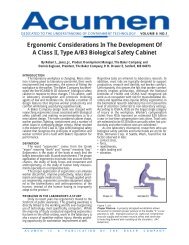
SterilGARD III Advance SG403 / SG603 - Baker Company
SterilGARD III Advance SG403 / SG603 - Baker Company
SterilGARD III Advance SG403 / SG603 - Baker Company

Create successful ePaper yourself
Turn your PDF publications into a flip-book with our unique Google optimized e-Paper software.
4 Seal off the exhaust opening by taping around the external damper and the slot, or by taping<br />
a piece of cardboard or plastic over the opening. If the cabinet is connected to an external<br />
exhaust, close the gas tight damper or remove ductwork to allow sealing.<br />
5 Remove the light canopy, the electrical panel, and the window tracks.<br />
6 Seal the front window opening by taping a piece of heavy gauge plastic around the<br />
perimeter of the opening.<br />
Warning!<br />
Decontaminate the unit before pressurizing, if it has contaminated<br />
plenums.<br />
7 Perform cabinet integrity test (per NSF 49).<br />
8 Repair leaks, as necessary.<br />
9 Restore the cabinet to operating status. Be sure to remove the sealing material, clean the<br />
cabinet, and reassemble all components.<br />
Electrical Safety Tests<br />
Since electrical components may become damaged in transport, we recommend qualified<br />
technicians retest them, before the cabinet is used.<br />
Note: Gasketed panels may not provide a good electrical ground.<br />
The electrical leakage, ground circuit resistance, and polarity were tested at our factory before<br />
shipment to ensure that there is no risk of electrical shock present in your cabinet. Since<br />
electrical components may become damaged in transport, we recommend qualified technicians<br />
retest them, before the cabinet is used. The electrical safety tests should also be performed at<br />
prescribed intervals as specified by an industrial hygienist, safety officer or other qualified<br />
person. EN61010-1 Standard recommends a dielectric strength test of 1350VAC, 1910VDC,<br />
and a total current leakage of 3.5ma from primary circuits to ground.<br />
Note: While performing the electrical safety tests, ensure that the connections with the test<br />
leads are solid, as poor connections will increase the resistance reading. Also, ensure that<br />
the exposed metal being touched is solidly connected to the cabinet frame. Gasketed panels<br />
may not provide a reliable measurement.<br />
Calibration procedure for Modus Inflow and Downflow alarms<br />
Note: This procedure MUST be followed every time the damper width has been changed.<br />
Nominal Set Point Settings<br />
1 Balance the cabinet air flows to nominal operating set point per manufacturer instruction.(<br />
See instruction label on front of cabinet).<br />
2 Record voltage to motor/blower (M1, M2 on speed control) and measure and record<br />
damper/ slot width<br />
3 Calibrate the downflow alarm as directed.<br />
13