SterilGARD III Advance SG403 / SG603 - Baker Company
SterilGARD III Advance SG403 / SG603 - Baker Company
SterilGARD III Advance SG403 / SG603 - Baker Company
You also want an ePaper? Increase the reach of your titles
YUMPU automatically turns print PDFs into web optimized ePapers that Google loves.
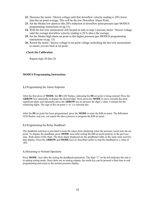
22. Decrease the motor / blower voltage until that downflow velocity reading is 20% lower<br />
than the set point average. This will be the low Downflow Alarm Point.<br />
23. Set the Modus low alarm to this 20% reduction in downflow point pressure (per MODUS<br />
programming instructions on pg.15).<br />
24. With the hot wire anemometer still located as note in step 1,increase motor / blower voltage<br />
until the average downflow velocity reading is 20 % above the average.<br />
25. Set the Modus high alarm set point to this higher pressure (per MODUS programming<br />
instructions on pg. 15).<br />
26. Return the motor / blower voltage to set point voltage rechecking the hot wire anemometer<br />
to ensure you are back at set point.<br />
Check the Calibration<br />
Repeat steps 20 thru 26<br />
MODUS Programming Instructions<br />
1.) Programming the Alarm Setpoints<br />
After the first press of MODE, the HI LED flashes, indicating the HI set point is being entered. Press the<br />
ARROW key repeatedly to display the desired digit. Next, press the MODE to move towards the most<br />
significant digit, and repeatedly press the ARROW key to advance the digit’s value. Continue for the<br />
remaining digits. The sign of the set point (+ or -) is selected last.<br />
After the HI set point has been programmed, press the MODE to enter the LO set point. The LO alarm<br />
LED flashes, and you can repeat the above process to program the LO set point.<br />
2.) Programming the Relay Deadband<br />
The deadband selection is provided to keep the relays from chattering when the pressure varies near the set<br />
point. To display the deadband, press MODE once after setting the LO set point polarity in the previous<br />
step. Both alarm LEDs flash. The three digits displayed are the deadband width, in the same units used for<br />
data display. Press the ARROW and MODE keys as described earlier to step the deadband to a value of<br />
.002.<br />
3.) Returning to Normal Operation<br />
Press MODE once after the setting the deadband parameters. The digit “1” on the left indicates the unit is<br />
in analog setting mode. Since there are no analog outputs, the mode key can be pressed a final time to end<br />
programming and return to the normal pressure display.<br />
15


