SterilGARD III Advance SG403 / SG603 - Baker Company
SterilGARD III Advance SG403 / SG603 - Baker Company
SterilGARD III Advance SG403 / SG603 - Baker Company

You also want an ePaper? Increase the reach of your titles
YUMPU automatically turns print PDFs into web optimized ePapers that Google loves.
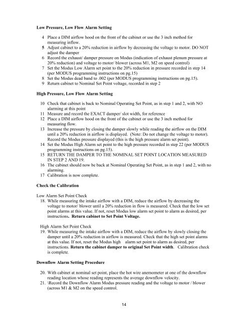
Low Pressure, Low Flow Alarm Setting<br />
4 Place a DIM airflow hood on the front of the cabinet or use the 3 inch method for<br />
measuring inflow.<br />
5 Adjust cabinet to a 20% reduction in airflow by decreasing the voltage to motor. DO NOT<br />
adjust the damper<br />
6 Record the exhaust/ damper pressure on Modus (indication of exhaust plenum pressure at<br />
20% reduction) and voltage to motor/ blower (across M1, M2 on speed control)<br />
7 Set the Modus Low Alarm set point to the 20% reduction in pressure recorded in step 14<br />
(per MODUS programming instructions on pg.15)<br />
8 Set the Modus dead band to .002 (per MODUS programming instructions on pg.15).<br />
9 Return cabinet to Nominal Set Point voltage, recorded in step 2<br />
High Pressure, Low Flow Alarm Setting<br />
10 Check that cabinet is back to Nominal Operating Set Point, as in step 1 and 2, with NO<br />
alarming at this point<br />
11 Measure and record the EXACT damper/ slot width, for reference<br />
12 Place a DIM airflow hood on the front of the cabinet or use the 3 inch method for<br />
measuring flow.<br />
13 Increase the pressure by closing the damper slowly while reading the airflow on the DIM<br />
until a 20% reduction in airflow is displayed. (Note: Do not change the voltage to motor).<br />
Record the Modus pressure displayed (this is the high pressure alarm set point).<br />
14 Set the Modus High Alarm set point to the high pressure recorded in step 22 (per MODUS<br />
programming instructions on pg.15).<br />
15 RETURN THE DAMPER TO THE NOMINAL SET POINT LOCATION MEASURED<br />
IN STEP 2 AND 19.<br />
16 The cabinet should now be back at Nominal Operating Set Point, as in step 1 and 2, with no<br />
alarming.<br />
17 Calibration is now complete.<br />
Check the Calibration<br />
Low Alarm Set Point Check<br />
18. While measuring the intake airflow with a DIM, reduce the airflow by decreasing the<br />
voltage to motor/ blower until a 20% reduction in flow is measured. Check that the low set<br />
point alarms at this value. If not, reset Modus low alarm set point to alarm as desired, per<br />
instructions. Return cabinet to Set Point Voltage.<br />
High Alarm Set Point Check<br />
19. While measuring the intake airflow with a DIM, reduce the airflow by slowly closing the<br />
damper until a 20% reduction in airflow is measured. Check that the high set point alarms<br />
at this value. If not, reset the Modus high alarm set point to alarm as desired, per<br />
instructions. Return the cabinet damper to original Set Point width. Calibration check<br />
is complete.<br />
Downflow Alarm Setting Procedure<br />
20. With cabinet at nominal set point, place the hot wire anemometer at one of the downflow<br />
reading location whose reading represents the average downflow velocity.<br />
21. \Record the Downflow Alarm Modus pressure reading and the voltage to motor / blower<br />
(across M1 & M2 on the speed control.<br />
14