Download User Instruction (3MB PDF) - Leckey
Download User Instruction (3MB PDF) - Leckey
Download User Instruction (3MB PDF) - Leckey

Create successful ePaper yourself
Turn your PDF publications into a flip-book with our unique Google optimized e-Paper software.
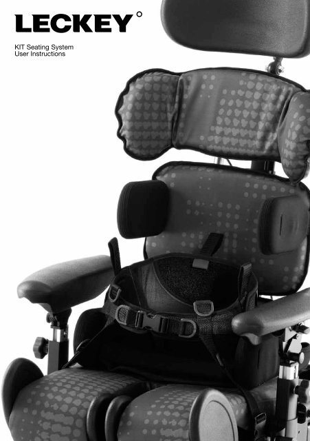
KIT Seating System<br />
<strong>User</strong> <strong>Instruction</strong>s
The KIT Seating System has been<br />
designed to offer a high level of<br />
postural positioning while enabling<br />
function and mobility. This manual<br />
shows you how to quickly, easily<br />
and safely make use of all the<br />
functions. The instructions on<br />
safety and maintenance will ensure<br />
that you will enjoy the use of this<br />
product for a long time.<br />
Contents<br />
01 Intended use<br />
02 Declaration of Conformity<br />
03 Terms of Warranty<br />
04 Product Record History<br />
05 Product Training Records<br />
06 Safety Information<br />
07 How to unpack and assemble the seating system and fit the cushions<br />
08 Clinical Setup for Postural Management<br />
09 Cleaning and Care Information<br />
10 Daily Product Inspection<br />
11 Annual Product Inspection<br />
12 Reissuing <strong>Leckey</strong> products<br />
13 Product Servicing<br />
14 Technical Information
6 Safety Information<br />
1. Intended Use<br />
The KIT Seating System is a seat that<br />
has been designed for use by adults<br />
and teenagers (from 12 years old) with<br />
disabilities, in the home, in day centres,<br />
in schools and outdoors, if used on a<br />
mobility base. The seating system has a<br />
maximum user weight of 75kg (165lbs).<br />
The seating system is modular and can be<br />
used with a choice of indoor or outdoor<br />
chassis. The Hi-low chassis has been<br />
designed for indoor use but can also be<br />
used outdoors on an even surface. The<br />
Hi-low chassis should never be exposed<br />
to the elements as this may corrode the<br />
metal components.<br />
The Kit seat unit will interface with a<br />
range of mobility bases, the details of<br />
which can be found on our website,<br />
www.leckey.com.<br />
2. Declaration of Conformity<br />
James <strong>Leckey</strong> Design Ltd as manufacturer<br />
with sole responsibility declares that<br />
the Kit Seating System conforms to the<br />
requirements of the 93/42/EEC Guidelines,<br />
Medical Device Regulations 2002 and EN<br />
12182 Technical aids for disabled persons<br />
and test methods.<br />
3. Terms of Warranty<br />
The warranty applies only when the<br />
product is used according to the<br />
specified conditions and for the intended<br />
purposes, following all manufacturers’<br />
recommendations (also see general terms<br />
of sales, delivery and payment). A two<br />
year warranty is provided on all <strong>Leckey</strong><br />
manufactured products and components.<br />
4. Product History Record<br />
Your <strong>Leckey</strong> product is classified as a<br />
Class 1 Medical Device and as such<br />
should only be prescribed, set up or<br />
reissued by a technically competent<br />
person who has been trained in the use<br />
of this product. <strong>Leckey</strong> recommend that<br />
a written record is maintained to provide<br />
details of all set ups, reissue inspections<br />
and annual inspections of this product.<br />
5. Product Training Record<br />
(Parents, Teachers & Carers)<br />
Your <strong>Leckey</strong> product is classified as a<br />
Class 1 Medical Device and as such<br />
<strong>Leckey</strong> recommend that parents, teachers<br />
and carers using the equipment should<br />
be made aware of the following sections<br />
of this user manual by a technically<br />
competent person:<br />
Section 6<br />
Safety Information<br />
Section 8<br />
Clinical Set up for Postural Management<br />
Section 9<br />
Cleaning and Care<br />
Section 10<br />
Daily Product Inspection<br />
<strong>Leckey</strong> recommend that a written record<br />
is maintained of all those who have trained<br />
in the correct use of this product.<br />
6.1 Always read instructions fully before<br />
use.<br />
6.2 <strong>User</strong>s should not be left unattended at<br />
any time while using <strong>Leckey</strong> equipment.<br />
6.3 Only use <strong>Leckey</strong> approved components<br />
with your product. Never modify the<br />
product in any way. Failure to follow<br />
instructions may put the user or carer<br />
at risk and will invalidate the warranty on<br />
the product.<br />
6.4 If in any doubt to the continued safe<br />
use of your product or if any parts should<br />
fail, please cease using the product and<br />
contact our customer services department<br />
or local dealer as soon as possible.<br />
6.5 Carry out all positional adjustments<br />
and ensure that they are securely fastened<br />
before you put the user into this product.<br />
Some adjustments may require the use of<br />
a tool which is provided with each product.<br />
Keep all tools out of reach of children.<br />
6.6 When placing the user into a seating<br />
system, for safety and positional reasons,<br />
always secure the Pelvic Cradle first.<br />
6.7 When the product is stationary ensure<br />
that all wheels are locked and facing away<br />
from the base as this will improve product<br />
stability. This is especially important<br />
when the tilt in space or back recline<br />
facility is in use.<br />
6.8 When the seat is in use on the Hi-low<br />
chassis we do not recommend that the<br />
users are moved over uneven surfaces<br />
when in the equipment. All due care<br />
and attention should be taken when<br />
transporting the user in and out of the seat.<br />
6.9 Never leave the product on a sloping<br />
surface, greater than 5 degrees. Always<br />
remember to lock all the wheels.<br />
6.10 Only use the push handles to steer<br />
and move the seat from one area to<br />
another. Never use the tray for this<br />
purpose.<br />
6.11 The product contains components<br />
which could present a choking hazard to<br />
small children. Always check that locking<br />
knobs and bolts within the user’s reach are<br />
tightened and secure at all times.<br />
6.12 <strong>Leckey</strong> products comply with fire<br />
safety regulations in accordance with<br />
EN12182. However the product contains<br />
plastic components and therefore should<br />
be kept away from all direct sources of<br />
heat including naked flames, cigarettes,<br />
electric and gas heaters.<br />
6.13 Do not place hot items greater than<br />
40º centigrade on the tray.<br />
6.14 Clean the product regularly. Do<br />
not use abrasive cleaners. Carry out<br />
maintenance checks on a regular basis to<br />
ensure your product is in good working<br />
condition.<br />
6.15 When the product is not in use, it<br />
should be stored in a dry place that is not<br />
subjected to extremes of temperature. The
safe operating temperature range of the<br />
product is +5 to +40 degrees Celsius.<br />
6.16 Always check the ratchet handles on<br />
the push handle are tightened securely<br />
before you move the seat unit.<br />
6.17 Before using the seating system<br />
always check that the interface handle<br />
on the seat unit is fully engaged with the<br />
chassis and the locking pin is engaged.<br />
If the handle is not engaged properly, the<br />
seat unit may come loose and could cause<br />
serious injury to the user or carer.<br />
KIT Seating System –<br />
Crash Test<br />
The KIT Seating System has been crash<br />
tested and passed for use in vehicles.<br />
It has been tested in its complete<br />
configuration on a surrogate base with a<br />
<strong>Leckey</strong> head support attached.<br />
If the KIT Seating System is being used<br />
in a vehicle, the following points must be<br />
adhered to:<br />
The KIT Seating System must be<br />
positioned forward facing and used<br />
with an Unwin Restraint System and a<br />
<strong>Leckey</strong> head support, which should be<br />
suitably positioned at all times during<br />
transportation. The head support is<br />
available as an optional accessory with<br />
the KIT Seating System.<br />
The KIT Seating System is crash tested<br />
and meets the requirements of ISO 16840<br />
part 4. The seat has also been tested and<br />
meets the requirements of ISO 7176-19.<br />
The crash tests were carried out using<br />
a chest harness and Pelvic Cradle.<br />
For further details please contact our<br />
Customer Service Department.<br />
Important<br />
If you are using the KIT Seating System<br />
on a wheelchair base, please refer to the<br />
wheelchair manufacturer’s handbook for<br />
crash test details.<br />
How to<br />
unpack and<br />
assemble<br />
the seating<br />
system and fit<br />
the cushions<br />
7
Check parts<br />
Congratulations on purchasing your KIT<br />
Seating System. When opening the box,<br />
take care not to cut through the tape as<br />
you may damage some of the parts<br />
contained inside. All of the parts will be<br />
contained in polythene bags with each<br />
one clearly labelled. Carefully remove them<br />
from the boxes and check all the parts you<br />
have ordered.<br />
Safety First<br />
Keep polythene bags away from children.<br />
Some of the accessories will need to be<br />
assembled before you attach them to the<br />
seat base you have purchased. If you are<br />
fitting the seat to a mobility base, please<br />
ensure you fit the interface plate to the<br />
mobility base first. <strong>Instruction</strong>s on how to<br />
attach the interface to specific bases will be<br />
provided with the interface plate. Once you<br />
have checked all the components you are<br />
ready to assemble the KIT Seating System<br />
and attach it to its base. Please follow the<br />
order suggested as it is often easier to fit the<br />
cushions before assembling the hardware.<br />
Tools<br />
A number of the adjustments will require<br />
the use of the multi-tool, T-bar allen key or<br />
a 13mm spanner which are provided with<br />
each seat.<br />
7.1 Attaching the Seating<br />
System to the Hi-low Chassis<br />
Before attaching the seat unit to the base<br />
raise the height of the chassis to its maximum<br />
to reduce the risk of back strain.<br />
Release the safety locking pin at the front of<br />
the seat by pulling the pin (A) out and rotating<br />
it through 90 degrees. Carefully tilt the seat<br />
and place it onto the chassis, locating the<br />
channel (B) at the rear of the seat over the<br />
tube at the back of the chassis (C).<br />
Pull the handle (D) at the front of the seat<br />
unit up and then pivot the seat down.<br />
Once the seat is fully lowered, release the<br />
handle and push it forward to ensure it has<br />
fully engaged on the front tube. Rotate the<br />
safety locking pin (A) so that it engages in the<br />
front of the handle.<br />
Always check the handle and locking pin<br />
are fully engaged before you place the user<br />
in the seating system. If the handle is not<br />
engaged properly, the seat unit can come<br />
loose and could cause serious injury to the<br />
user or the carer.<br />
B<br />
C<br />
D<br />
A<br />
A
7.2 Removable<br />
Backrest spine<br />
7.3 Fixed Backrest<br />
spine<br />
7.4 Seat Base<br />
Cushion<br />
The removable backrest spine will be<br />
detached for shipping. Insert it into the side<br />
plates of the seat base, slipping the front pin<br />
(A) into the front slot (B) on both sides of the<br />
seat base. Angle the spine back. Place the<br />
pin (C) through the base of the spine.<br />
If the fixed backrest spine option has been<br />
ordered, simply rotate the backrest into the<br />
vertical position and insert pin (A) through the<br />
base of the spine.<br />
Fasten the two poppers (A) at the back of the<br />
seatbase. Press the cushion down onto the<br />
Velcro which is on the leg support ramps.<br />
Loop the elastic over the hooks (B) on the<br />
side of the seatbase.<br />
A<br />
B<br />
A<br />
B<br />
A<br />
C<br />
A<br />
B
7.5 Sacral support<br />
7.6 Hip Laterals<br />
7.7 Contoured sacral<br />
support<br />
7.8 Thoracic Support<br />
Fit the sacral cushion over the hardware and<br />
fasten at the back with the poppers. The<br />
standard sacral support should be attached<br />
with the double flaps (A) at the top.<br />
To attach the sacral support, slide the<br />
support onto the lowest mounting bracket on<br />
the backrest spine. Secure it with a bolt (B)<br />
on either side. Cover the bracket with a spine<br />
upholstery shroud (C).<br />
To attach the hip laterals to the standard<br />
sacral support, loosen the screw (A) and<br />
insert the bar of the hip lateral into the hole<br />
on the side of the sacral support. Tighten the<br />
screw to secure.<br />
To attach the hip lateral covers, slide the<br />
cover over the lateral support.<br />
To fit the contoured sacral support cushion,<br />
loosen the laterals using the screw (A) on the<br />
hinge. Insert laterals into pockets and fasten<br />
poppers on back.<br />
Slide the support onto the lowest mounting<br />
bracket on the backrest spine. Secure it with<br />
a bolt (B) on either side. Cover the bracket<br />
with a spine upholstery shroud (C).<br />
Fit the cushion over the hardware and fasten<br />
at the back with the poppers.<br />
Slide the support onto the middle mounting<br />
bracket on the backrest spine. Secure it with<br />
a bolt (A) on either side. Cover the bracket<br />
with a spine upholstery shroud (B).<br />
A<br />
B<br />
A<br />
B<br />
A<br />
A<br />
C<br />
C<br />
B
7.9 Standard and<br />
Complex Thoracic<br />
Laterals<br />
The standard and complex (horizontal and<br />
vertical) laterals are attached in the same<br />
way to the thoracic support. Before attaching<br />
laterals, remove the thoracic cushion.<br />
Before removing the bolt from the bracket<br />
components, make a note of the order in<br />
which the pieces fit together.<br />
While holding the rest of the components<br />
together, remove the bolt and washer (A)<br />
with the Allen tool. Keeping the rest of the<br />
components together, place the plastic<br />
moulding into the slot (B). The bar should go<br />
into the recess of the thoracic support. Insert<br />
the bolt from the back and tighten. Fit the<br />
lateral covers.<br />
7.10 Angle<br />
Adjustable Thoracic<br />
Laterals<br />
The angle adjustable laterals are attached to<br />
the standard thoracic support. Position the<br />
lateral brackets over the slot in the thoracic<br />
supports and secure with two bolts (A).<br />
Fit the cushion cover over the hardware and<br />
secure with the poppers.<br />
7.11 Shoulder Support<br />
To fit the shoulder support cushion, loosen<br />
the laterals using the screw (A) on the hinge.<br />
Insert laterals into pockets and fasten poppers<br />
on back.<br />
Slide the support onto the top mounting<br />
bracket on the backrest spine. Secure it with<br />
a bolt (B) on either side. Cover the bracket<br />
with a spine upholstery shroud (C).<br />
A<br />
A<br />
A<br />
B<br />
B<br />
B<br />
C
7.12 Pelvic Cradle<br />
7.13 Chest Pad<br />
7.14 Chest Harness<br />
Fasten the front buckle and side Velcro tabs of<br />
the Pelvic Cradle. Ensure the “Back” label (A)<br />
is against the backrest and the “Seat” label (B)<br />
is on the seatbase cushion. Stick the Velcro<br />
down to the seatbase cushion. Attach the four<br />
side release buckles (C), two at the back of the<br />
seatbase and two at the side.<br />
Screw the buckles onto the thoracic laterals.<br />
Attach the chest pad to the buckles (A).<br />
We recommend that lateral covers are always<br />
fitted when using the chest pad. To attach<br />
lateral covers, slide them over the lateral<br />
ensuring that the slot is on the outside to<br />
access the chest pad attachment buckle.<br />
To attach the chest harness to the shoulder<br />
section, first remove the cushion and plastic<br />
cover. Feed the webbing into the holes (A) in<br />
the mouldings and fasten with the nuts and<br />
bolts provided. Attach the top straps to these<br />
buckles. The lower straps attach onto the<br />
buckles on the sacral support. If the standard<br />
sacral support is used, attach the webbing<br />
through the holes (B) at the top of the<br />
moulding and fasten with the nuts and bolts<br />
provided. If the contoured sacral cushion is<br />
used, attach the webbing through the holes<br />
(C) at the bottom of the moulding and fasten<br />
with the nuts and bolts provided.<br />
A<br />
B<br />
B<br />
A<br />
C<br />
C<br />
A
A<br />
7.15 Headrest<br />
7.16 Femoral Gables 7.17 Foot Supports<br />
To attach the head support (<strong>Leckey</strong> or<br />
Otto Bock) slide the stem into the receiving<br />
bracket (A) and secure by tightening the<br />
screw (B).<br />
The KIT Seating System has been designed<br />
to interface with Whitmyer head supports and<br />
a range of other supports that require a box<br />
section receiving bracket. Insert the Whitmyer<br />
interface bracket box section into the top<br />
of the spine. Secure the head support onto<br />
this bracket.<br />
Femoral gables are attached to the seat base<br />
using bolts (A). There are two bolts for each<br />
gable. Bolts should be firmly secured.<br />
Loosen the leg support nuts (A) on the<br />
underside of the seat base with a spanner.<br />
Move the leg supports forward one at a<br />
time. This makes it easier to insert the foot<br />
supports. Open the screws (B) and slide in<br />
the foot supports from the centre. Retighten<br />
the screws. Reposition the leg supports and<br />
retighten nuts.<br />
Always make sure the foot supports are<br />
attached securely.<br />
Whitmyer bracket<br />
A<br />
Box section bracket<br />
B<br />
A<br />
A<br />
B
A<br />
7.18 Attaching the<br />
Sandal Straps<br />
7.19 Armrests<br />
7.20 Tray<br />
Sandal straps can be attached to the foot<br />
supports. Feed the back straps through the<br />
slots in the rear of the sandals. Remove the<br />
bolts on the underside of the sandals, thread<br />
the bolts (A) through the ends of the straps<br />
and refasten. The front straps are simply<br />
fed from below through the front slots on<br />
the sandals.<br />
To attach the armrests, loosen the ratchet<br />
handles (A) and insert the armrests with<br />
the side with the adjustment knobs (B)<br />
facing outwards.<br />
Before attaching the tray, ensure the armrests<br />
are at the same height and angle. The tray<br />
is attached to the seat by inserting the tray<br />
tubes through the centre of the armrest.<br />
Tighten knob (A) to secure.<br />
B<br />
A<br />
A<br />
A
7.21 Attaching the Foam<br />
Spacer Pads<br />
7.22 Setting up the<br />
Push Handle<br />
7.23 Interfaces for<br />
wheelchair bases<br />
The foam spacer pads can be used to<br />
support an obliquity or under the thighs. They<br />
can be cut to size and attached using Velcro.<br />
Unfold the push handle until straight and<br />
secure in position with the spring popper (A)<br />
at either side.<br />
The set up and attachment of the KIT<br />
seat to any mobility base should be<br />
completed by a technically competent<br />
person who is familiar with the set up of<br />
the mobility base.<br />
The <strong>Leckey</strong> Mobility Base is built with an<br />
interface which fits the KIT seat.<br />
45cm Discovery Interface attachment to<br />
18” (450mm) wide mobility base<br />
The KIT seat can be easily attached to the<br />
Discovery 45cm wide wheel base.<br />
Always refer to the mobility base<br />
manufacturer’s guidelines for correct set<br />
up, paying particular attention to product<br />
centre of gravity and stability.<br />
A thorough risk assessment should be<br />
carried out when attaching the KIT Seat to<br />
any mobility base not supplied by <strong>Leckey</strong>.<br />
Please refer to specific assembly instructions<br />
supplied with your interface for correct<br />
positioning of your base. The interface<br />
should be fitted by a qualified technician<br />
who is technically competent in the set up<br />
of the mobility base. The position of the<br />
push handles, leg hangers and armrests on<br />
the mobility base may need to be adjusted<br />
depending on the size and weight of the user<br />
to ensure the stability of the seat.<br />
<strong>Leckey</strong> Mobility Base<br />
45cm Discovery Base<br />
A<br />
A
Clinical<br />
Set up for<br />
Postural<br />
Management<br />
8.1 Backrest angle 8.2 Backrest Height<br />
To change the angle loosen the screw (A) at<br />
the bottom of the backrest spine, adjust to<br />
the required position and retighten the screw<br />
securely.<br />
The backrest angle can be adjusted with the<br />
user in the seat.<br />
Hold the backrest spine with one hand<br />
while you adjust the back angle.<br />
To adjust the overall height of the backrest<br />
loosen the screw (A), adjust the shoulder<br />
section to the required position and retighten<br />
the screw securely. The height can be fine<br />
tuned with the user in the seat.<br />
Use caution when adjusting to minimum<br />
setting as fingers could become trapped<br />
between moving and static parts.<br />
The clinical set up of the product should<br />
be completed by a technically and clinically<br />
competent person who has been trained in<br />
the use of the product. <strong>Leckey</strong> recommend<br />
a written record is kept of all clinical set<br />
ups for this product.<br />
<strong>Leckey</strong> recommend that a full supine lying<br />
and unsupported sitting assessment is<br />
carried out prior to setting up the product.<br />
Set the height and angle of each backrest<br />
section (A), the seat depth (B) and the foot<br />
support height (C) before placing the user<br />
in the seat. These can be fine tuned when<br />
the user is in the seat.<br />
C<br />
B<br />
A<br />
8<br />
A<br />
A<br />
A
8.3 Pelvic Cradle 8.4 Gluteal ramp<br />
8.5 Sacral Support<br />
When setting up the Pelvic Cradle for the first<br />
time with the client in it, the Pelvic Cradle<br />
should be flat and open before the user is<br />
placed into the Kit Seating System. All four<br />
side and back buckles should be already<br />
attached to the seat. When the client is placed<br />
in the seat, first fasten the buckle (A) at the<br />
front of the Pelvic Cradle. Then fasten the<br />
Velcro (B) at the sides to fit the Pelvic Cradle<br />
to the user. Then adjust the front and rear<br />
straps (C) and (D) to secure to position the<br />
user’s pelvis.<br />
If a gluteal ramp (A) is required, it can be<br />
attached by Velcro to the front of the<br />
Pelvic Cradle before the user is placed into<br />
the seat.<br />
The sacral support can be adjusted in a<br />
number of ways - height, depth and angle.<br />
To adjust the height or the depth, remove the<br />
spine upholstery shroud and loosen the two<br />
screws (A) on either side of the bracket. Move<br />
the sacral support to the required position,<br />
height and depth. Retighten the screws and<br />
replace the spine upholstery shroud.<br />
To adjust the angle of the sacral support,<br />
loosen both the screws (B) on the ball and<br />
socket joint. Position the support at the<br />
required angle. Retighten the screws.<br />
After initial set up, only the front<br />
buckle (A) needs to be released when<br />
the user is transferred in or out of the KIT<br />
Seating System.<br />
Once a week, check that the Pelvic Cradle<br />
has not become slack.<br />
B<br />
B<br />
B<br />
D<br />
B<br />
A<br />
A<br />
A<br />
C
A<br />
8.6 Hip Laterals<br />
8.7 Contoured Sacral<br />
Support<br />
The hip laterals can be width and angle<br />
adjusted to suit the user’s requirements.<br />
Loosen the screws (A) at the back of the<br />
sacral support. Move the hip laterals to<br />
required position. Ideally the hip laterals<br />
should always be rotated so they rest on top<br />
of the seat cushion even if the backrest or<br />
sacral support is angled. Once the hip laterals<br />
are in position, retighten the screws securely.<br />
The laterals can also be angled to<br />
help support abduction, adduction or<br />
windsweeping.<br />
To adjust the angle of the hip laterals loosen<br />
the screw (B) on the hinge of the hip lateral.<br />
Adjust to the required angle. Retighten the<br />
screw. The pads can also be adjusted in<br />
depth and a small degree of rotation by<br />
loosening the screws (C) on the pad, sliding it<br />
to the required position and retightening the<br />
screws.<br />
The contoured sacral support can be<br />
adjusted in a number of ways - height, depth<br />
and angle.<br />
To adjust the height or the depth, remove the<br />
spine upholstery shroud and loosen the two<br />
screws (A) on either side of the bracket. Move<br />
the sacral support to the required position.<br />
Retighten the screws and replace the spine<br />
upholstery shroud.<br />
To adjust the angle of the sacral support,<br />
loosen both the screws (B) on the ball and<br />
socket joint. Position the support at the<br />
required angle. Retighten the screws.<br />
The lateral supports can be angle adjusted<br />
to contour the pad and provide lateral pelvic<br />
support. To angle, loosen screw C, set to<br />
required angle and retighten securely.<br />
C<br />
A<br />
B<br />
B<br />
B<br />
C<br />
C<br />
B<br />
C<br />
A
8.8 Thoracic Support<br />
8.9 Standard and Complex<br />
Thoracic Laterals<br />
The thoracic support can be adjusted in<br />
a number of ways: height, lateral position<br />
and angle.<br />
To adjust the height, remove the spine<br />
upholstery shroud, loosen the two screws (A)<br />
on either side of the mounting bracket, slide<br />
to the required position and then retighten<br />
the screws securely.<br />
To adjust the thoracic support laterally or in<br />
angle, loosen both the screws (B) on the ball<br />
and socket joint, position the support at the<br />
required angle or lateral position and then<br />
retighten the screws securely.<br />
B<br />
B<br />
The standard and complex laterals, horizontal<br />
and vertical options can be used in whatever<br />
combination is most suited to the user’s<br />
requirements. It is possible to attach more<br />
than one lateral to the same side of the<br />
thoracic support if required.<br />
To adjust the height, width or angle of these<br />
laterals, loosen the screw (A) on the lateral<br />
mounting. Position the lateral at the required<br />
height, width and angle. Retighten the screw.<br />
The complex laterals can also be angled to<br />
allow the pad to contour to the user’s shape.<br />
To adjust loosen the screw (B) at the centre<br />
of the pad, angle the pad to the required<br />
position and retighten the screw.<br />
All of the laterals can be flipped away to aid<br />
transfer, by pulling the pin (C) at the back and<br />
rotating the support out of the way.<br />
B<br />
A<br />
A<br />
A<br />
C
8.10 Angle Adjustable<br />
Thoracic Laterals<br />
8.11 Shoulder Support<br />
To adjust the angle of the laterals, loosen the<br />
screws (A) at the hinges. Contour the laterals<br />
to the required angle. Retighten the screws.<br />
The laterals have a small degree of depth<br />
and rotational adjustment for more proximal<br />
positioning. Loosen screws (B) adjust the pad<br />
and retighten the screws securely.<br />
The shoulder support can be adjusted<br />
in a number of ways – height, depth<br />
and angle.<br />
To adjust the height or the depth, remove<br />
the spine upholstery shroud, loosen the two<br />
screws (A) on either side of the mounting<br />
bracket. Move the shoulder support to the<br />
required position. Retighten the screws and<br />
replace the spine upholstery shroud.<br />
If further height adjustment is required, please<br />
refer to the section on Backrest Height.<br />
The Size 2 shoulder support can also be<br />
attached to the Size 1 seat to further increase<br />
the backrest height.<br />
To adjust the angle of the whole shoulder<br />
support, loosen both the screws (B) on the<br />
ball and socket joint. Position the support at<br />
the required angle. Retighten the screws.<br />
To adjust the angle of the wings of the<br />
shoulder support, loosen both the screws (C)<br />
at the hinges. Contour the shoulder support to<br />
the required shape. Retighten the screws.<br />
B<br />
A<br />
B<br />
B<br />
C<br />
B<br />
A
8.12 Headrest 8.13 Seat Base Depth<br />
To adjust the height of the headrest, loosen<br />
the screw (A) at the top of the backrest spine.<br />
Position the headrest to the required<br />
height to suit the user’s head position.<br />
Retighten the screw.<br />
To position the headrest, loosen one or both<br />
of the plastic handles (B) at the hinges of the<br />
headrest mounting. Position the headrest as<br />
required. Retighten the screws.<br />
To change the profile of the Profiling<br />
Contoured Headrest, remove the cover,<br />
loosen the screws (D), set to the required<br />
position and retighten screws. Fit the<br />
cover again.<br />
To adjust the position of the Lateral Headrest<br />
loosen screw (E), position as required and<br />
retighten the screw.<br />
To adjust the seat base depth, loosen the nuts<br />
(A) underneath the upper leg supports with a<br />
spanner. Move the upper leg support in or out<br />
to the required position and retighten the nuts<br />
securely. It is possible to upgrade the Size 1<br />
seat base to achieve the same seat depth size<br />
as the Size 2 seat.<br />
8.14 Seat base – Upper Leg<br />
Support Angle for Windsweep<br />
-ing, Abduction or Adduction<br />
To adjust the upper leg support angle<br />
loosen the nuts (A) underneath the upper leg<br />
supports, adjust to the required angle and<br />
then retighten the nuts securely.<br />
To angle or rotate the head support, loosen<br />
screws (C), set to required position and<br />
retighten securely.<br />
C<br />
A<br />
A<br />
B<br />
A<br />
A<br />
A<br />
D<br />
E
8.15 Femoral Gables 8.16 Foot support height<br />
8.17 Calf Support 8.18 Foot support - size<br />
Large and small femoral gables may be<br />
used in any combination to suit the user’s<br />
requirements, or they may be removed<br />
altogether. To adjust the angle or width of<br />
the femoral gables, loosen the screws (A) and<br />
position as required. Retighten the screws.<br />
There are two screws per femoral gable.<br />
To raise or lower the height of the foot<br />
support, loosen the screw (A) adjust to the<br />
required position and retighten the screw<br />
securely.<br />
To adjust the calf support angle, loosen the<br />
screw (A) at the top of the calf support, move<br />
front or back to the required angle, then<br />
retighten screw.<br />
To change the size of the foot supports to<br />
accommodate different shoe sizes, loosen the<br />
screws (A) at the toes of the foot supports.<br />
Adjust the foot support to the required size.<br />
Retighten the screws.<br />
Note: A 5mm tool is required.<br />
A<br />
A<br />
A<br />
A
8.19 Foot support - angle 8.20 Armrest<br />
8.21 Tilt in Space<br />
To change the angle of the complex foot<br />
supports, loosen the three screws (A) on the<br />
ball and socket joint on the underside of the<br />
foot support. Change the angle to suit the<br />
user’s requirements. Retighten the screws.<br />
Note: A 5mm tool is required.<br />
To flip away the complex or basic foot<br />
supports, pull out the pin (B) at the back of<br />
the sandals and rotate it through 90°. Holding<br />
your thumb on C, slide the foot support<br />
outwards, away from the centre line, then<br />
flip up. The foot support locks in the vertical<br />
position.<br />
C<br />
B<br />
To adjust the armrest height, loosen the knob<br />
(A), adjust to the required height and retighten<br />
the knob. To adjust the angle pull the pin (B)<br />
out and rotate the armrest to the required<br />
position, then release the pin ensuring the pin<br />
is securely located in one of the holes.<br />
Armrest pads can be moved forwards<br />
or backwards by removing screws (C),<br />
repositioning the armrest pad and reattaching<br />
securely in position with the screws.<br />
The tilt in space can be angled when the<br />
user is in the seat. Before you adjust the tilt<br />
in space angle of the seat always ensure that<br />
the Pelvic Cradle is secured, preventing the<br />
user from sliding forwards in the seat.<br />
To adjust the tilt angle, pull the lever on the<br />
push handles, tilt the seat to the required<br />
angle and remove your hand from the lever.<br />
Always hold push handles securely before<br />
using the tilt in space lever.<br />
C<br />
C<br />
A<br />
B<br />
B<br />
A<br />
C<br />
B<br />
C
8.22 Hi-low Chassis –<br />
Height Adjustment<br />
9 Cleaning & Care<br />
Information<br />
You can carry out this adjustment with the<br />
user in the chair. If your chassis has the foot<br />
pedal locking pin (A), disengage it first. To<br />
unlock, pull the pin out and rotate through 90<br />
degrees. To adjust the height of the hydraulic<br />
Hi-low chassis press the foot lever (B) at the<br />
rear of the chassis. Once you remove your<br />
foot from the pedal, the seat will be fixed at<br />
this height. To lower the height place foot<br />
under the pedal and lift up, the seat height will<br />
gradually lower.<br />
For safety always engage the pull pin (A)<br />
after adjustment, if applicable.<br />
To adjust the height of the powered base,<br />
use the buttons on the handset. Before<br />
the product is used for the first time, it is<br />
recommended that the battery is fully charged<br />
for 12 hours. To do this, plug the adaptor<br />
into the mains socket and attach the lead<br />
to the battery. Switch on the mains power<br />
supply. When charged, switch off the mains<br />
power supply, remove the adaptor plug and<br />
disconnect the lead from the battery. The<br />
battery charge should be topped up each<br />
day until the green light on the charge is<br />
illuminated. The chair can be adjusted while<br />
attached to the mains.<br />
Ensure that the product and user are<br />
away from surrounding furnishings when<br />
adjusting the height to prevent possible<br />
collisions and injury to the user or damage<br />
to the product.<br />
How to Maintain<br />
When cleaning the product we recommend<br />
that you use only warm water and a<br />
nonabrasive detergent. Never use organic<br />
solvents or dry cleaning fluids.<br />
Upholstery and fabrics<br />
1. The upholstery and fabrics can be<br />
removed and machine washed and tumble<br />
dried at a low setting. The standard covers<br />
can be washed at 40ºC and the Infection<br />
Control covers at 90ºC. Please remove the<br />
foam before washing the following covers:<br />
Shoulder support<br />
Thoracic support<br />
Sacral support<br />
Contoured sacral support<br />
Seat base.<br />
All other soft upholstery can be placed<br />
directly in the washing machine. Use a wash<br />
bag to prevent covers being damaged in the<br />
washing machine.<br />
Metal and plastic components<br />
1. Soap and water or antibacterial spray can<br />
be used for daily cleaning.<br />
2. For deep cleaning a low pressure steam<br />
cleaner can be used.<br />
3. Do not use solvents to clean plastic or<br />
metal components.<br />
4. Make sure the product is dry before use.<br />
2. If the upholstery is to be cleaned in-situ,<br />
the best cleaning method is a ‘wipe & dry’<br />
technique.<br />
3. Staining should be removed as quickly<br />
as possible with absorbent cloth, towels or<br />
a sponge. Routine soap and warm water<br />
sponging is effective for ordinary soiling and<br />
minor spills. Be careful not to over wet the<br />
fabric, as this will cause the staining<br />
to spread.<br />
4. Always ensure the product is dry<br />
before use.<br />
A<br />
B
10 Daily Product Inspection<br />
11 Annual Product<br />
Inspection<br />
(Therapists, parents & carers)<br />
We recommend that daily visual checks of<br />
the equipment are carried out by therapists,<br />
carers or parents to ensure the product is<br />
safe for use. The recommended daily checks<br />
are detailed below.<br />
Seat Checks<br />
1. Ensure all adjustment knobs and bolts<br />
are in place and secure.<br />
2. Check all upholstery for signs of wear<br />
and tear.<br />
3. Check all Velcro strips and brush fluff to<br />
ensure straps secure firmly.<br />
4. Check all back support components<br />
are secure.<br />
Chassis Checks<br />
1. Check all wheels are moving freely and<br />
lock securely.<br />
2. Check height adjustment is working and<br />
pedal is locking.<br />
3. Check tilt in space is working and<br />
locking securely.<br />
4. Check locking pin on the interface handle<br />
is in its locked position.<br />
If in any doubt to the continued safe<br />
use of your <strong>Leckey</strong> product or if any<br />
parts should fail, please cease using the<br />
product and contact our customer service<br />
department or your local dealer as soon<br />
as possible.<br />
(Therapist, Technician, <strong>Leckey</strong> Product<br />
Advisor, Dealer)<br />
<strong>Leckey</strong> recommend that each product should<br />
be subject to a detailed inspection at least<br />
once a year and every time the product is<br />
reissued for use. This inspection should<br />
be carried out by a technically competent<br />
person who has been trained in the use of<br />
the product and should include the following<br />
checks as a minimum requirement.<br />
1. Check all knobs, nuts, bolts and plastic<br />
buckles are in place, replacing any missing<br />
items. Paying particular attention to the<br />
following items;<br />
- Buckles and Velcro on Pelvic Cradle<br />
- Seat interface handle locks and releases<br />
- Tilt in space and height adjustment work<br />
and lock securely<br />
- All ball and socket joints lock securely,<br />
shoulder, thoracic, sacral and foot supports<br />
- Backrest angle adjusts and locks securely<br />
- Leg supports angle adjust and<br />
lock securely<br />
- Armrest height and angle adjust and<br />
lock securely<br />
- Head support locks securely<br />
2. Lift the base to check each wheel<br />
individually. Make sure they are moving<br />
freely and remove any dirt from the rubber<br />
wheels. Check that the brakes lock the<br />
wheels securely.<br />
3. Visually check the structure of the product<br />
paying attention to weld points on the frame<br />
ensuring there are no signs of fatigue or<br />
cracking around the welds.<br />
4. <strong>Leckey</strong> recommend that a written record is<br />
maintained of all annual product inspections.<br />
If in any doubt to the continued safe<br />
use of your <strong>Leckey</strong> product or if any<br />
parts should fail, please cease using the<br />
product and contact our customer<br />
service department or your local dealer<br />
as soon as possible.
12 Re-issuing <strong>Leckey</strong><br />
Products<br />
13 Product Servicing<br />
14 Technical<br />
Information<br />
Most <strong>Leckey</strong> products are assessed and<br />
ordered to meet the needs of an individual<br />
user. Before reissuing a product we<br />
recommend that the therapist prescribing<br />
the product has carried out an equipment<br />
compatibility check for the new user and<br />
has ensured that the product being<br />
re-issued contains no modifications or<br />
special attachments.<br />
A detailed technical inspection should be<br />
carried on the product prior to re-issuing.<br />
This should be carried out by a technically<br />
competent person who has been trained in<br />
the use and inspection of the product.<br />
Please refer to section 11 for the required<br />
checks to be carried out.<br />
Ensure the product has been cleaned<br />
thoroughly in accordance with section 9<br />
of this manual.<br />
Ensure a copy of the user manual is supplied<br />
with the product. A copy can be downloaded<br />
from our website www.leckey.com.<br />
<strong>Leckey</strong> recommend that a written record is<br />
maintained of all product inspections carried<br />
out during the reissue of the product.<br />
If in any doubt to the continued safe<br />
use of your <strong>Leckey</strong> product or if any<br />
parts should fail, please cease using the<br />
product and contact our customer service<br />
department or your local dealer as soon<br />
as possible.<br />
Servicing of all <strong>Leckey</strong> products should only<br />
be carried out by technically competent<br />
persons who have been trained in the use of<br />
the product.<br />
In the UK & ROI please contact the <strong>Leckey</strong><br />
Service Centre on UK 0800 318265 or ROI<br />
1800 626020 and our customer service<br />
department will be delighted to assist you<br />
with your servicing requirements.<br />
All international service enquiries should be<br />
directed to the appropriate <strong>Leckey</strong> distributor<br />
who will be delighted to assist you. For<br />
further information on <strong>Leckey</strong> distributors<br />
please visit our website www.leckey.com.<br />
Product and Accessory Codes<br />
133-1600-FIX Size 1 seat shell assembly<br />
fixed backrest<br />
133-1600-REM Size 1 seat shell assembly<br />
removable backrest<br />
139-2600-FIX Size 2 seat shell assembly<br />
fixed backrest<br />
139-2600-REM Size 2 seat shell assembly<br />
removable backrest<br />
133-404* Size 1 castellated foam seat<br />
base cushion and cover<br />
139-404* Size 2 castellated foam seat<br />
base cushion and cover<br />
133-405* Size 1 memory foam seat<br />
base cushion and cover<br />
139-405* Size 2 memory foam seat<br />
base cushion and cover<br />
133-611 Size 1 shoulder support<br />
assembly<br />
139-611 Size 2 shoulder support<br />
assembly<br />
133-400* Size 1 shoulder support<br />
cushion and cover<br />
139-400* Size 2 shoulder support<br />
cushion and cover<br />
133-605 Thoracic support assembly<br />
133-401* Thoracic cushion and cover<br />
133-619 Angle adjustable thoracic<br />
laterals hardware<br />
133-402* Angle adjustable thoracic<br />
cushion and cover<br />
133-612 Sacral support assembly<br />
133-403* Sacral support cushion and<br />
cover<br />
133-604 Size 1 contoured sacral<br />
support<br />
133-400* Size 1 contoured sacral<br />
support cushion and cover<br />
133-1620 Lateral Headrest<br />
For product codes marked with *, please add<br />
the following colour option codes:<br />
+10 Blue +11 Grey<br />
+12 Purple +13 Grey Infection Control<br />
Chassis<br />
133-750 Kit Hi-low base – hydraulic<br />
133-760 Kit Hi-low base – powered<br />
133-770 <strong>Leckey</strong> Mobility base<br />
133-740 45cm Discovery base and<br />
mobility interface<br />
Mobility Interface Options<br />
139-726 45mm Discovery interface A<br />
Accessories<br />
133-728 Pelvic Cradle Size 0<br />
133-729 Pelvic Cradle Size 1<br />
133-730 Pelvic Cradle Size 2<br />
133-731 Pelvic Cradle Size 3<br />
133-608 Hip lateral pads (pair)<br />
133-737 Pelvic Cradle gluteal ramp<br />
133-609 Flip away laterals (single<br />
without covers)<br />
133-747 Lateral covers (single)<br />
133-622-RH Flip away complex laterals -<br />
horizontal right hand<br />
(single with covers)<br />
133-622-LH Flip away complex laterals -<br />
horizontal left hand<br />
(single with covers)<br />
133-614-RH Flip away complex laterals -<br />
vertical right hand<br />
(single with covers)<br />
133-614-LH Flip away complex laterals -<br />
vertical left hand<br />
(single with covers)<br />
133-625 Chest pad<br />
133-1626 Chest harness Size 1<br />
133-2626 Chest harness Size 2<br />
133-3626 Chest harness Size 3<br />
133-627 Profiling contoured headrest<br />
133-716 Profiling contoured headrest<br />
cover<br />
133-626 PU contoured headrest<br />
133-735 Armrests (pair)<br />
133-635 Tray – clear<br />
133-624 Tray – grey<br />
133-680 Padded tray insert<br />
133-721 Leg straps (pair)<br />
133-601 Femoral Gable Pack<br />
(2 large and 2 small)<br />
133-682 Large femoral gables – right<br />
133-686 Large femoral gables – left<br />
133-683 Small femoral gables – right<br />
133-687 Small femoral gables – left<br />
133-1005 Foam spacer pack<br />
(for obliquity)<br />
133-606 Foot supports - ball and<br />
socket joints (pair)<br />
133-607 Foot supports – basic (pair)<br />
133-712 Sandal straps size 1<br />
133-742 Sandal straps size 2<br />
133-765 Spine upholstery shroud (set)<br />
133-726 Lateral / bracket protector<br />
covers (single)<br />
133-749 Whitmyer bracket<br />
133-745 Head Support bracket for 1/2”<br />
and 15mm Box Section<br />
WASH01 Washing machine bag
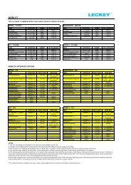
KIT seat dimensions<br />
<strong>Leckey</strong> Hi Low base options<br />
Product sizing Size 1 Size 2<br />
mm inches mm inches<br />
KIT Hi-low chassis<br />
mm<br />
inches<br />
Age range 12-18 yrs 16-adult<br />
Stature range<br />
Min 1400 55.1 1600 63.0<br />
Max 1650 65.0 1850 73.0<br />
Max user weight (kg/lbs) 75 165.0 75 165.0<br />
Seat depth<br />
Min 360 14.2 410 16.1<br />
Max 480 18.9 560 22.0<br />
Max windsweep accommodation 20° 20° 20° 20°<br />
Max seat width - without laterals 430 16.9 430 16.9<br />
Seat width - with hip laterals<br />
Min 215 8.5 215 8.5<br />
Max 370 14.6 370 14.6<br />
Backrest height<br />
Min 500 19.7 560 22.0<br />
Max 620 24.4 675 26.6<br />
Shoulder width<br />
Min 190 7.5 260 10.2<br />
Max 500 19.7 600 23.6<br />
Chest width<br />
Min 230 9.1 230 9.1<br />
Max 380 15.0 380 15.0<br />
Backrest angle 90°-120° 90°-120° 90°-120° 90°-120°<br />
Seat to footplate<br />
Min 330 13.0 330 13.0<br />
Max 510 20.1 510 20.1<br />
Armrest height<br />
Min 265 10.4 265 10.4<br />
Max 380 15.0 380 15.0<br />
Top of seat to floor<br />
Min 460 18<br />
Max 640 25<br />
With handle folded down<br />
Length 700 27.6<br />
Width 620 24.4<br />
Height 410 16<br />
LINAK Actuator specification<br />
- 281209-01<br />
Rated IP51<br />
Duty Cycle Max 10% or 2 min continuous<br />
use followed by 18 min not in use.<br />
Ambient temp +5deg to +40deg C<br />
Ambient Operating temp 22deg<br />
Storage temp -40deg C to 70degC<br />
Push Max 3500N<br />
Pull Max 2000N<br />
Self Lock at 3500N Push – 2000N Pull<br />
Typical speed with full load 4.7mm/sec<br />
Max amps at load of 3500N is 3.9 amps<br />
Noise level dB(A) 48<br />
Power input voltage 24v +- 10%<br />
LINAK Battery Box - BA18021-00<br />
Rated IP51<br />
Ambient temp +5deg to 40deg C<br />
Storage temp -20deg C to 60deg C<br />
Rated Capacity 1.2 Ah 24v<br />
Charging current is max 0.3A<br />
Lead acid gel filled battery<br />
LINAK Handset - HB41000-00004<br />
Rated IP51<br />
Control current 100mA per channel (Max)<br />
Ambient temp +5deg to +40deg C<br />
LINAK Battery Charger - CH01<br />
Mains 100-240 VAC/50-60 Hz switch mode<br />
power supply<br />
Charging voltage 27.6 VDC +- 2%<br />
Charging current Max 500mA<br />
Green LED for power on<br />
Yellow LED for charging function<br />
Yellow LED turns into green when batteries<br />
are fully charged.<br />
LINAK products may be stored in non-heated<br />
storage facilities with humidity between<br />
0 and 100%, none condensing. None<br />
condensing means that one should not take<br />
a product from an ice cold warehouse into<br />
a room with a temperature of 20deg C;<br />
if this is done then moistness will appear<br />
on the products.<br />
Tray size 630 x 460 24.8 X 18.1 630 X 460 24.8 X 18.1<br />
Seat weight (seat & back) 20.5 Kg 45.1 Lbs 21 kg 46.2 Lbs
<strong>Leckey</strong><br />
19 Ballinderry Road<br />
Lisburn<br />
BT28 2SA<br />
Northern Ireland<br />
United Kingdom<br />
T: 028 9260 1044<br />
E: info@leckey.com<br />
W: www.leckey.com<br />
24 hour postural<br />
care for babies,<br />
kids & adults.<br />
Sleeping, Sitting,<br />
Standing, Walking,<br />
Moving, Bathing,<br />
Toileting.<br />
LS240-03