15" PLANER INSTRUCTION MANUAL - Grizzly Industrial Inc.
15" PLANER INSTRUCTION MANUAL - Grizzly Industrial Inc.
15" PLANER INSTRUCTION MANUAL - Grizzly Industrial Inc.

Create successful ePaper yourself
Turn your PDF publications into a flip-book with our unique Google optimized e-Paper software.
Feed Roller Height<br />
The infeed and outfeed rollers move the lumber<br />
through the planer, and press the lumber flat<br />
against the planer table.<br />
Set the infeed and outfeed rollers to 0.02"-0.04"<br />
below the cutterhead knife edge at bottom dead<br />
center.<br />
To check roller height:<br />
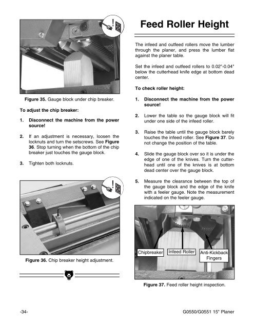
Figure 35. Gauge block under chip breaker.<br />
To adjust the chip breaker:<br />
1. Disconnect the machine from the power<br />
source!<br />
2. If an adjustment is necessary, loosen the<br />
locknuts and turn the setscrews. See Figure<br />
36. Stop turning when the bottom of the chip<br />
breaker just touches the gauge block.<br />
3. Tighten both locknuts.<br />
1. Disconnect the machine from the power<br />
source!<br />
2. Lower the table so the gauge block will fit<br />
under one side of the infeed roller.<br />
3. Raise the table until the gauge block barely<br />
touches the infeed roller. See Figure 37. Do<br />
not change the position of the table.<br />
4. Slide the gauge block over so it is under the<br />
edge of one of the knives. Turn the cutterhead<br />
until one of the knives is at bottom<br />
dead center over the gauge block.<br />
5. Measure the clearance between the top of<br />
the gauge block and the edge of the knife<br />
with a feeler gauge. Note the measurement<br />
indicated on the feeler gauge.<br />
Figure 36. Chip breaker height adjustment.<br />
Chipbreaker Infeed Roller Anti-Kickback<br />
Fingers<br />
Figure 37. Feed roller height inspection.<br />
-34- G0550/G0551 15" Planer