15" PLANER INSTRUCTION MANUAL - Grizzly Industrial Inc.
15" PLANER INSTRUCTION MANUAL - Grizzly Industrial Inc.
15" PLANER INSTRUCTION MANUAL - Grizzly Industrial Inc.
Create successful ePaper yourself
Turn your PDF publications into a flip-book with our unique Google optimized e-Paper software.
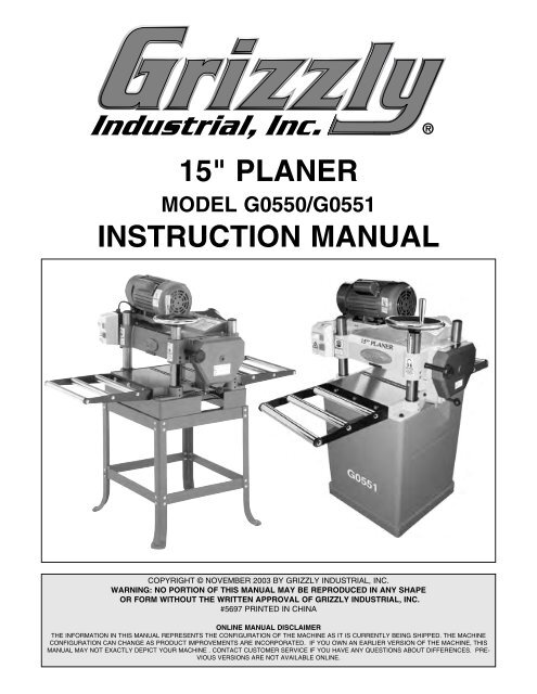
15" <strong>PLANER</strong><br />
MODEL G0550/G0551<br />
<strong>INSTRUCTION</strong> <strong>MANUAL</strong><br />
COPYRIGHT © NOVEMBER 2003 BY GRIZZLY INDUSTRIAL, INC.<br />
WARNING: NO PORTION OF THIS <strong>MANUAL</strong> MAY BE REPRODUCED IN ANY SHAPE<br />
OR FORM WITHOUT THE WRITTEN APPROVAL OF GRIZZLY INDUSTRIAL, INC.<br />
#5697 PRINTED IN CHINA<br />
ONLINE <strong>MANUAL</strong> DISCLAIMER<br />
THE INFORMATION IN THIS <strong>MANUAL</strong> REPRESENTS THE CONFIGURATION OF THE MACHINE AS IT IS CURRENTLY BEING SHIPPED. THE MACHINE<br />
CONFIGURATION CAN CHANGE AS PRODUCT IMPROVEMENTS ARE INCORPORATED. IF YOU OWN AN EARLIER VERSION OF THE MACHINE, THIS<br />
<strong>MANUAL</strong> MAY NOT EXACTLY DEPICT YOUR MACHINE . CONTACT CUSTOMER SERVICE IF YOU HAVE ANY QUESTIONS ABOUT DIFFERENCES. PRE-<br />
VIOUS VERSIONS ARE NOT AVAILABLE ONLINE.
WARNING<br />
Some dust created by power sanding, sawing, grinding,<br />
drilling, and other construction activities contains<br />
chemicals known to the State of California to cause<br />
cancer, birth defects or other reproductive harm.<br />
Some examples of these chemicals are:<br />
• Lead from lead-based paints.<br />
• Crystalline silica from bricks, cement, and<br />
other masonry products.<br />
• Arsenic and chromium from chemically treated<br />
lumber.<br />
Your risk from these exposures varies, depending on<br />
how often you do this type of work. To reduce your<br />
exposure to these chemicals: work in a well ventilated<br />
area, and work with approved safety equipment, such<br />
as those dust masks that are specially designed to filter<br />
out microscopic particles.
Table Of Contents<br />
SECTION 1: SAFETY........................................................................................................................2<br />
Safety Instructions For Power Tools ..........................................................................................2<br />
Additional Safety Instructions For Planers..................................................................................4<br />
SECTION 2: INTRODUCTION ..........................................................................................................5<br />
SECTION 3: CIRCUIT REQUIREMENTS ........................................................................................6<br />
Amperage Draw ..........................................................................................................................6<br />
Circuit Breaker ............................................................................................................................6<br />
Plug-Type....................................................................................................................................6<br />
Circuit Capacity ..........................................................................................................................7<br />
Grounding ..................................................................................................................................7<br />
Extension Cords..........................................................................................................................7<br />
SECTION 4: MACHINE FEATURES ................................................................................................8<br />
Common Terms & Definitions ....................................................................................................9<br />
SECTION 5: SET UP ......................................................................................................................10<br />
Parts Inventory ..........................................................................................................................10<br />
Hardware Recognition Chart ....................................................................................................12<br />
Site Considerations ..................................................................................................................13<br />
Clean Up ..................................................................................................................................13<br />
Beginning Assembly..................................................................................................................14<br />
G0550 Open Stand ..................................................................................................................14<br />
Mounting Planer (G0550)..........................................................................................................15<br />
Dust Port ..................................................................................................................................16<br />
Handwheel ................................................................................................................................16<br />
Extension Rollers ......................................................................................................................17<br />
Knife Setting Jig ........................................................................................................................18<br />
Start Up ....................................................................................................................................19<br />
Recommended Adjustments ....................................................................................................19<br />
SECTION 6: OPERATIONS ............................................................................................................20<br />
Cutterhead Locks ......................................................................................................................20<br />
Power Feed ..............................................................................................................................21<br />
Handwheel ................................................................................................................................21<br />
Depth Limiter ............................................................................................................................21<br />
Anti-Kickback ............................................................................................................................22<br />
Wood Species ..........................................................................................................................22<br />
SECTION 7: MAINTENANCE ........................................................................................................23<br />
Maintenance Safety ..................................................................................................................23<br />
Table ........................................................................................................................................23<br />
V-Belts ......................................................................................................................................24<br />
Gearbox ....................................................................................................................................25<br />
Lubrication ................................................................................................................................25<br />
Planing Difficulties ....................................................................................................................27<br />
SECTION 8: SERVICE ADJUSTMENTS ........................................................................................28<br />
Gauge Blocks............................................................................................................................28<br />
Table Adjustment ......................................................................................................................29<br />
Thickness Scale ........................................................................................................................30<br />
Knife Inspection ........................................................................................................................31<br />
Knife Sharpening ......................................................................................................................32<br />
Knife Setting..............................................................................................................................32<br />
Chip Breaker ............................................................................................................................33<br />
Feed Roller Height ....................................................................................................................34<br />
Bed Rollers................................................................................................................................35<br />
Feed Roller Pressure ................................................................................................................36<br />
Chip Deflector ..........................................................................................................................37<br />
SECTION 9: REFERENCE INFO ....................................................................................................38<br />
Aftermarket Accessories ..........................................................................................................39<br />
G0550/G0551 Parts Breakdown ..............................................................................................42<br />
Troubleshooting Guide..............................................................................................................47<br />
G0550/G0551 Wiring Diagram..................................................................................................48<br />
Gauge Block Measurements ....................................................................................................49<br />
Warranty & Returns ..................................................................................................................50
SECTION 1: SAFETY<br />
For Your Own Safety Read Instruction<br />
Manual Before Operating This Equipment<br />
The purpose of safety symbols is to attract your attention to possible hazardous conditions.<br />
This manual uses a series of symbols and signal words which are intended to convey the level<br />
of importance of the safety messages. The progression of symbols is described below.<br />
Remember that safety messages by themselves do not eliminate danger and are not a substitute<br />
for proper accident prevention measures.<br />
Indicates an imminently hazardous situation which, if not avoided,<br />
WILL result in death or serious injury.<br />
Indicates a potentially hazardous situation which, if not avoided,<br />
COULD result in death or serious injury.<br />
Indicates a potentially hazardous situation which, if not avoided,<br />
MAY result in minor or moderate injury. It may also be used to alert<br />
against unsafe practices.<br />
NOTICE<br />
This symbol is used to alert the user to useful information about<br />
proper operation of the equipment.<br />
Safety Instructions For Power Tools<br />
1. KEEP GUARDS IN PLACE and in working<br />
order.<br />
2. REMOVE ADJUSTING KEYS AND<br />
WRENCHES. Form a habit of checking to<br />
see that keys and adjusting wrenches are<br />
removed from tool before turning on.<br />
3. KEEP WORK AREA CLEAN. Cluttered<br />
areas and benches invite accidents.<br />
4. NEVER USE IN DANGEROUS ENVIRON-<br />
MENT. DO NOT use power tools in damp<br />
or wet locations, or where any flammable<br />
or noxious fumes may exist. Keep work<br />
area well lighted.<br />
5. KEEP CHILDREN AND VISITORS<br />
AWAY. All children and visitors should be<br />
kept at a safe distance from work area.<br />
6. MAKE WORKSHOP CHILD PROOF with<br />
padlocks, master switches, or by removing<br />
starter keys.<br />
7. NEVER FORCE TOOL. It will do the job<br />
better and safer at the rate for which it was<br />
designed.<br />
8. USE RIGHT TOOL. DO NOT force tool or<br />
attachment to do a job for which it was not<br />
designed.<br />
-2- G0550/G0551 15" Planer
Safety Instructions For Power Tools<br />
9. USE PROPER EXTENSION CORD. Make<br />
sure your extension cord is in good condition.<br />
Conductor size should be in accordance<br />
with the chart below. The amperage<br />
rating should be listed on the motor or tool<br />
nameplate. An undersized cord will cause<br />
a drop in line voltage resulting in loss of<br />
power and overheating. Your extension<br />
cord must also contain a ground wire and<br />
plug pin. Always repair or replace extension<br />
cords if they become damaged.<br />
Minimum Gauge for Extension Cords<br />
LENGTH<br />
AMP RATING 25ft 50ft 100ft<br />
0-6 16 16 16<br />
7-10 16 16 14<br />
11-12 16 16 14<br />
13-16 14 12 12<br />
17-20 12 12 10<br />
21-30 10 10 No<br />
10. WEAR PROPER APPAREL. DO NOT<br />
wear loose clothing, gloves, neckties,<br />
rings, bracelets, or other jewelry which may<br />
get caught in moving parts. Non-slip<br />
footwear is recommended. Wear protective<br />
hair covering to contain long hair.<br />
11. ALWAYS USE SAFETY GLASSES. Also<br />
use face or dust mask if cutting operation is<br />
dusty. Everyday eyeglasses only have<br />
impact resistant lenses, they are NOT safety<br />
glasses.<br />
12. SECURE WORK. Use clamps or a vise to<br />
hold work when practical. It’s safer than<br />
using your hand and frees both hands to<br />
operate tool.<br />
13. DO NOT OVER-REACH. Keep proper<br />
footing and balance at all times.<br />
14. MAINTAIN TOOLS WITH CARE. Keep<br />
tools sharp and clean for best and safest<br />
performance. Follow instructions for lubricating<br />
and changing accessories.<br />
15. USE RECOMMENDED ACCESSORIES.<br />
Consult the owner’s manual for recommended<br />
accessories. The use of improper<br />
accessories may cause risk of injury.<br />
16. REDUCE THE RISK OF UNINTENTION-<br />
AL STARTING. On machines with magnetic<br />
contact starting switches there is a risk of<br />
starting if the machine is bumped or jarred.<br />
Always disconnect from power source<br />
before adjusting or servicing. Make sure<br />
switch is in OFF position before reconnecting.<br />
17. CHECK DAMAGED PARTS. Before further<br />
use of the tool, a guard or other part<br />
that is damaged should be carefully<br />
checked to determine that it will operate<br />
properly and perform its intended function.<br />
Check for alignment of moving parts, binding<br />
of moving parts, breakage of parts,<br />
mounting, and any other conditions that<br />
may affect its operation. A guard or other<br />
part that is damaged should be properly<br />
repaired or replaced.<br />
18. NEVER LEAVE TOOL RUNNING UNAT-<br />
TENDED. TURN POWER OFF. DO NOT<br />
leave tool until it comes to a complete stop.<br />
19. NEVER OPERATE A MACHINE WHEN<br />
TIRED, OR UNDER THE INFLUENCE OF<br />
DRUGS OR ALCOHOL. Full mental alertness<br />
is required at all times when running a<br />
machine.<br />
20. NEVER ALLOW UNSUPERVISED OR<br />
UNTRAINED PERSONNEL TO OPER-<br />
ATE THE MACHINE. Make sure any<br />
instructions you give in regards to machine<br />
operation are approved, correct, safe, and<br />
clearly understood.<br />
21. IF AT ANY TIME YOU ARE EXPERIENC-<br />
ING DIFFICULTIES performing the intended<br />
operation, stop using the machine! Then<br />
contact our service department or ask a<br />
qualified expert how the operation should<br />
be performed.<br />
G0550/G0551 15" Planer -3-
Additional Safety Instructions For Planers<br />
1. READ THIS ENTIRE <strong>MANUAL</strong> BEFORE<br />
TURNING THE <strong>PLANER</strong> ON.<br />
2. ENSURE THAT THE MACHINE IS ON<br />
FLAT, STABLE GROUND BEFORE USE.<br />
Any “wobbles” must be corrected by shimming<br />
or blocking before operation.<br />
3. NEVER PLANE MATERIAL OTHER<br />
THAN WOOD STOCK WITH THIS<br />
MACHINE.<br />
4. NEVER POSITION FINGERS OR<br />
THUMBS NEAR THE INFEED ROLLER.<br />
5. ENSURE THAT THE <strong>PLANER</strong> IS PROP-<br />
ERLY ADJUSTED AND THAT THERE<br />
ARE NO LOOSE PARTS BEFORE<br />
OPERATING.<br />
6. PLANE IN THE SAME DIRECTION AS<br />
THE GRAIN OF THE WOOD STOCK.<br />
7. ALWAYS STAND TO THE SIDE OF THE<br />
<strong>PLANER</strong> WHILE FEEDING THE WORK-<br />
PIECE.<br />
8. DO NOT LOOK INSIDE THE <strong>PLANER</strong><br />
DURING OPERATION!<br />
9. ALWAYS PROVIDE ADEQUATE IN-<br />
FEED AND OUTFEED SPACE WHEN<br />
OPERATING THE <strong>PLANER</strong>. Always support<br />
long pieces of stock on both sides of<br />
the planer.<br />
10. DO NOT REMOVE MORE THAN 1 ⁄8"<br />
FROM THE SURFACE OF THE WOOD<br />
STOCK IN A SINGLE PASS.<br />
11. INSPECT YOUR STOCK BEFORE PLAN-<br />
ING. Never plane stock with nails, staples<br />
or other foreign objects which may be<br />
embedded in the surface. Always properly<br />
prepare workpieces before running them<br />
through the planer. Do not plane lumber<br />
with loose knots or knots that may become<br />
loose during planing.<br />
12. DO NOT ATTEMPT TO REMOVE JAMS<br />
UNTIL POWER IS DISCONNECTED and<br />
all moving parts have come to a complete<br />
stop.<br />
13. DO NOT PLANE WORKPIECES LESS<br />
THAN 12" LONG AND 1 ⁄4" THICK.<br />
14. DO NOT OPERATE <strong>PLANER</strong> WITH DULL<br />
OR DAMAGED KNIVES.<br />
15. ALWAYS UNPLUG THE <strong>PLANER</strong> WHEN-<br />
EVER MAKING ANY ADJUSTMENTS or<br />
changing knives.<br />
16. IF AT ANY TIME YOU ARE EXPERIENC-<br />
ING DIFFICULTIES PERFORMING THE<br />
INTENDED OPERATION, STOP USING<br />
THE <strong>PLANER</strong>! Then contact our service<br />
department or ask a qualified expert how<br />
the operation should be performed.<br />
Like all machines there is danger associated<br />
with the Model G0550/G0551. Accidents are<br />
frequently caused by lack of familiarity or<br />
failure to pay attention. Use this machine<br />
with respect and caution to lessen the possibility<br />
of operator injury. If normal safety<br />
precautions are overlooked or ignored, serious<br />
personal injury may occur.<br />
No list of safety guidelines can be complete.<br />
Every shop environment is different. Always<br />
consider safety first, as it applies to your<br />
individual working conditions. Use this and<br />
other machinery with caution and respect.<br />
Failure to do so could result in serious personal<br />
injury, damage to equipment, or poor<br />
work results.<br />
-4- G0550/G0551 15" Planer
SECTION 2: INTRODUCTION<br />
Commentary<br />
Lack of familiarity with<br />
this manual could<br />
cause serious personal<br />
injury. Become<br />
familiar with the contents<br />
of this manual,<br />
including all the safety<br />
warnings.<br />
We are proud to offer the Model G0550/G0551<br />
15" Planer. This machine is part of a growing<br />
<strong>Grizzly</strong> family of fine woodworking machinery.<br />
When used according to the guidelines set forth<br />
in this manual, you can expect years of troublefree,<br />
enjoyable operation and proof of <strong>Grizzly</strong>’s<br />
commitment to customer satisfaction.<br />
We are pleased to provide this manual with the<br />
Model G0550/G0551. It was written to guide you<br />
through assembly, review safety considerations,<br />
and cover general operating procedures. It represents<br />
our effort to produce the best documentation<br />
possible. If you have any comments regarding<br />
this manual, please write to us at the address<br />
below:<br />
Most importantly, we stand behind our machines.<br />
If you have any service questions or parts<br />
requests, please call or write us at the location<br />
listed below.<br />
<strong>Grizzly</strong> <strong>Industrial</strong>, <strong>Inc</strong>.<br />
1203 Lycoming Mall Circle<br />
Muncy, PA 17756<br />
Phone: (570) 546-9663<br />
Fax: (800) 438-5901<br />
E-Mail: techsupport@grizzly.com<br />
Web Site: http://www.grizzly.com<br />
The specifications, drawings, and photographs<br />
illustrated in this manual represent the Model<br />
G0550/G0551 as supplied when the manual was<br />
prepared. However, owing to <strong>Grizzly</strong>’s policy of<br />
continuous improvement, changes may be made<br />
at any time with no obligation on the part of<br />
<strong>Grizzly</strong>. For your convenience, we always keep<br />
current <strong>Grizzly</strong> manuals available on our website<br />
at www.grizzly.com. Any updates to your<br />
machine will be reflected in these manuals as<br />
soon as they are complete. Visit our site often to<br />
check for the latest updates to this manual!<br />
<strong>Grizzly</strong> <strong>Industrial</strong>, <strong>Inc</strong>.<br />
C<br />
/O Technical Documentation<br />
P.O. Box 2069<br />
Bellingham, WA 98227-2069<br />
G0550/G0551 15" Planer -5-
SECTION 3: CIRCUIT REQUIREMENTS<br />
Amperage Draw<br />
Plug-Type<br />
The Model G0550/G0551 motor is wired to operate<br />
at 220V only. The planer motors draw the following<br />
amperage:<br />
Amperage Draw<br />
G0550 2 HP..........................................12 Amps<br />
G0551 3 HP..........................................18 Amps<br />
We recommend using a NEMA-style 6-15 plug<br />
and outlet with the G0550 as shown in Figure 1a<br />
and an L6-20 plug and outlet for the G0551 as<br />
shown in Figure 1b. You may also “hard-wire”<br />
the planer directly to your panel, provided you<br />
place a disconnect near the machine. Check the<br />
electrical codes in your area for specifics on<br />
wiring requirements.<br />
Circuit Breaker<br />
Use the following guidelines when choosing a circuit<br />
breaker (circuit breakers rated any higher are<br />
not adequate to protect the circuit):<br />
Circuit Breaker<br />
G0550 ........................................15 Amp, 2 Pole<br />
G0551 ........................................20 Amp, 2 Pole<br />
Figure 1a. NEMA 6-15 plug and receptacle.<br />
Figure 1b. NEMA L6-20 plug and receptacle.<br />
-6- G0550/G0551 15" Planer
Circuit Capacity<br />
Extension Cords<br />
Always check to see if the wires in your circuit are<br />
capable of handling the amperage draw from<br />
your machine, as well as any other machines that<br />
could be operating on the same circuit. If you are<br />
unsure, consult a qualified electrician.<br />
If the circuit breaker trips or the fuse blows regularly,<br />
your machine may be operating on a circuit<br />
that is close to its amperage draw capacity.<br />
However, if an unusual amperage draw does not<br />
exist and a power failure still occurs, contact a<br />
qualified electrician.<br />
Grounding<br />
220V Operation<br />
We do not recommend the use of extension cords<br />
on 220V equipment. Instead, arrange the placement<br />
of your equipment and the installed wiring to<br />
eliminate the need for extension cords.<br />
If you find it absolutely necessary to use an<br />
extension cord at 220V with your <strong>Grizzly</strong> Planer:<br />
• Make sure the cord is rated for Standard<br />
Service (grade S) or better.<br />
• The extension cord must also contain a<br />
ground wire and plug prong.<br />
• Use at least a 16 gauge cord if the cord is 50<br />
feet long or less.<br />
• Use at least a 14 gauge cord if the cord is<br />
between 51-100 feet.<br />
Electrocution or a fire can<br />
result if the machine is<br />
not grounded correctly.<br />
Make sure all electrical<br />
circuits are grounded. DO<br />
NOT use the machine if it<br />
is not grounded.<br />
In the event of an electrical short, grounding<br />
reduces the risk of electric shock by providing a<br />
path of least resistance to disperse electric current.<br />
This tool is equipped with a power cord that<br />
has an equipment-grounding prong. The outlet<br />
must be properly installed and grounded in accordance<br />
with all local codes and ordinances.<br />
G0550/G0551 15" Planer -7-
SECTION 4: MACHINE FEATURES<br />
V-Belt Cover<br />
Motor<br />
Depth Limiter<br />
Height<br />
Handwheel<br />
Height Lock<br />
Knob<br />
Power Switch<br />
Thickness<br />
Scale<br />
Feed Rate Knob<br />
Extension Rollers<br />
Bed Rollers<br />
Figure 2. Machine features.<br />
-8- G0550/G0551 15" Planer
Common Terms & Definitions<br />
Work Table: The wood moves through the planer<br />
on the work table.<br />
Infeed and Outfeed Rollers: Powered rollers<br />
that move the wood through the planer.<br />
Cutterhead: The cutterhead holds the knives<br />
and spins at 5000 rpm. When wood passes<br />
under the cutterhead, material is removed.<br />
Chip Breaker: Spring loaded fingers or bar that<br />
presses down on the wood in front of the cutterhead.<br />
The chip breaker prevents excessive<br />
chipping caused by the knives.<br />
Snipe: A gouge at the end of the board.<br />
Pressure Bar: Rides on the planed surface<br />
behind the cutterhead. Prevents vibration,<br />
chattering and snipe.<br />
Bed Rollers: Located in the work table, the bed<br />
rollers help wood move through the planer.<br />
Dust Hood: Funnels wood dust and chips into<br />
the dust collection system.<br />
Gibs: Metal strips that hold the planer knives in<br />
place.<br />
Gib Bolts: Secures the gib to the knife to keep it<br />
in place.<br />
G0550/G0551 15" Planer -9-
SECTION 5: SET UP<br />
About This Section<br />
Parts Inventory<br />
The purpose of this section is to guide you<br />
through the required steps to get your machine<br />
out of its packaging and into operating condition.<br />
This machine presents<br />
serious injury hazards<br />
to untrained users. Read<br />
through this entire manual<br />
to become familiar<br />
with the controls and<br />
operations before starting<br />
the machine!<br />
The Model G0550 comes with an open stand that<br />
requires assembly, and the Model G0551 comes<br />
assembled on a closed cabinet stand.<br />
The following is an inventory of the parts for your<br />
new Model G0550/G0551 Planer.<br />
Wear safety glasses during<br />
the entire set up<br />
process!<br />
Figure 3. G0550 planer unit.<br />
Unpacking<br />
The Model G0550/G0551 was carefully packed<br />
when it left our warehouse. If you discover the<br />
machine is damaged after you have signed for<br />
delivery, please immediately call Customer<br />
Service at (570) 546-9663 for advice.<br />
Save the containers and all packing materials for<br />
possible inspection by the carrier or its agent.<br />
Otherwise, filing a freight claim can be difficult.<br />
When you are completely satisfied with the condition<br />
of your shipment, you should inventory the<br />
parts.<br />
-10- G0550/G0551 15" Planer
H<br />
F<br />
G<br />
A<br />
E<br />
A<br />
B<br />
C<br />
E<br />
D<br />
B<br />
Figure 4. G0550 loose parts.<br />
G0550 Loose Parts<br />
DESCRIPTION<br />
QTY<br />
A. Extension Rollers ......................................2<br />
B. Dust Port ....................................................1<br />
C. Stand Hardware Bag..................................1<br />
— Carriage Bolts 5 ⁄16"-18 x 1 ⁄2"..................32<br />
— Hex Nuts 5 ⁄16"-18..................................36<br />
— Flat Washers 5 ⁄16" ................................36<br />
— Lock Washer 5 ⁄16" ..................................4<br />
— Hex Bolts 5 ⁄16"-18 x 1" ............................4<br />
D. Tool Bag ....................................................1<br />
— Handwheel Handle ................................1<br />
— Combo Wrench 8/10mm ......................1<br />
— Combo Wrench 12/14mm ....................1<br />
— Allen Wrench 6mm................................1<br />
— Allen Wrench 5mm................................1<br />
— Allen Wrench 4mm................................1<br />
— Allen Wrench 3mm................................1<br />
— Knife Jig Shaft ......................................1<br />
— Knife Jig Feet ........................................2<br />
— E-Clips 9mm..........................................4<br />
E. Handwheel Bag..........................................1<br />
— Handwheel ............................................1<br />
— High/Low Label......................................1<br />
— Flat Washer 10mm................................1<br />
— Hex Nut M10-1.5 ..................................1<br />
Extension Roller Hardware Bag ................1<br />
— Hex Bolt M8-1.25 x 20 ..........................6<br />
— Flat Washer 8mm..................................6<br />
— Setscrew M8-1.25 x 12 ........................6<br />
Dust Port Hardware Bag............................1<br />
— Phillips Head Screw M6-1.0 x 12 ..........6<br />
F. Legs ..........................................................4<br />
G. Lower Braces ............................................4<br />
H. Predrilled Upper Braces ............................4<br />
C<br />
Figure 5. G0551 loose parts.<br />
G0551 Loose Parts<br />
DESCRIPTION<br />
QTY<br />
A. Dust Port ....................................................1<br />
B. Extension Roller Hardware Bag ................1<br />
— Hex Bolts M8-1.25 x 20 ........................6<br />
— Flat Washers 8mm ................................6<br />
— Setscrews M8-1.25 x 12........................6<br />
C. Tool Bag ....................................................2<br />
— Handwheel Handle ................................1<br />
— Combo Wrench 8/10mm ......................1<br />
— Combo Wrench 12/14mm ....................1<br />
— Allen Wrench 6mm................................1<br />
— Allen Wrench 5mm................................1<br />
— Allen Wrench 4mm................................1<br />
— Allen Wrench 3mm................................1<br />
— Knife Jig Shaft ......................................1<br />
— Knife Jig Feet ........................................2<br />
— E-Clips 9mm..........................................4<br />
D. Handwheel Bag..........................................1<br />
— Handwheel ............................................1<br />
— High/Low Label......................................1<br />
— Flat Washer 10mm................................1<br />
— Hex Nut M10-1.5 ..................................1<br />
Foot Hardware Bag....................................1<br />
— Foot ......................................................4<br />
— Hex Nut M8-1.25 ..................................4<br />
Dust Port Hardware Bag............................1<br />
— Phillips Head Screw M6-1.0 x 12 ..........6<br />
E. Extension Rollers ......................................2<br />
D<br />
G0550/G0551 15" Planer -11-
Hardware Recognition Chart<br />
USE THIS CHART TO MATCH UP<br />
HARDWARE DURING THE ASSEMBLY<br />
PROCESS!<br />
MEASURE BOLT DIAMETER BY PLACING INSIDE CIRCLE<br />
4mm<br />
6mm<br />
8mm<br />
10mm<br />
12mm<br />
16mm<br />
#<br />
10<br />
1<br />
⁄4''<br />
5<br />
⁄16''<br />
3<br />
⁄8''<br />
7<br />
⁄16''<br />
1<br />
⁄2''<br />
5<br />
⁄8''<br />
LINES ARE 1MM APART<br />
Thumb<br />
Screw<br />
Cap<br />
Screw<br />
Setscrew<br />
Washer<br />
5mm<br />
10mm<br />
15mm<br />
20mm<br />
25mm<br />
30mm<br />
35mm<br />
40mm<br />
45mm<br />
50mm<br />
55mm<br />
60mm<br />
65mm<br />
70mm<br />
75mm<br />
1<br />
⁄4''<br />
3<br />
⁄8''<br />
1<br />
⁄2''<br />
5<br />
⁄8''<br />
Phillips<br />
Head<br />
Screw<br />
Carriage<br />
Bolt<br />
Hex<br />
Head<br />
Bolt<br />
Lock<br />
Washer<br />
LINES ARE 1 ⁄16'' INCH APART<br />
Countersunk<br />
Phillips<br />
Head<br />
Screw<br />
-12- G0550/G0551 15" Planer<br />
Lock<br />
Nut<br />
Hex<br />
Nut<br />
5<br />
⁄16''<br />
7<br />
⁄16''<br />
9<br />
⁄16''<br />
3<br />
⁄4''<br />
7<br />
⁄8''<br />
1''<br />
1 1 ⁄4''<br />
1 1 ⁄2''<br />
1 3 ⁄4''<br />
2<br />
2 1 ⁄4''<br />
2 1 ⁄2''<br />
2 3 ⁄4''<br />
3<br />
Flange<br />
Bolt<br />
Phillips<br />
Head<br />
Hex<br />
Bolt<br />
WASHERS ARE MEASURED BY THE INSIDE DIAMETER<br />
Wing<br />
Nut<br />
12mm<br />
WASHER DIAMETER<br />
10mm<br />
WASHER DIAMETER<br />
8mm<br />
WASHER DIAMETER<br />
Slotted<br />
Screw<br />
Button<br />
Head<br />
Screw<br />
Phillips<br />
Head<br />
Sheet<br />
Metal<br />
Screw<br />
WASHER DIAMETER<br />
4mm<br />
WASHER DIAMETER<br />
6mm<br />
ASHER DIAMETER<br />
W5⁄8''<br />
9<br />
⁄16''<br />
WASHER DIAMETER<br />
1<br />
⁄2''<br />
WASHER DIAMETER<br />
7<br />
⁄16''<br />
WASHER DIAMETER<br />
3<br />
⁄8''<br />
WASHER DIAMETER<br />
5<br />
⁄16''<br />
WASHER DIAMETER<br />
1<br />
⁄4''<br />
WASHER DIAMETER<br />
WASHER DIAMETER<br />
#<br />
10
Site Considerations<br />
Clean Up<br />
Floor Load<br />
The Model G0550 weighs 410 lbs and has a 25"<br />
x 25" footprint. The Model G0551 weighs 450 lbs<br />
and has a 21" x 21" footprint. Most commercial<br />
floors are suitable for the machine. Some residential<br />
floors may require additional reinforcement<br />
to support both the machine and operator.<br />
Working Clearances<br />
Consider existing and anticipated needs, size of<br />
material to be processed through each machine,<br />
and space for auxiliary stands, work tables or<br />
other machinery when establishing a location for<br />
the machine. See Figure 6 for the overall dimensions<br />
of the Model G0550/G0551.<br />
28"<br />
48"<br />
The unpainted surfaces are coated with a waxy<br />
oil to protect them from corrosion during shipment.<br />
Remove this protective coating with a solvent<br />
cleaner or citrus-based degreaser such as<br />
<strong>Grizzly</strong>’s G7895 Degreaser. To clean thoroughly,<br />
some parts may need to be removed. For optimum<br />
performance from your machine, make<br />
sure you clean all moving parts or sliding<br />
contact surfaces that are coated. Avoid chlorine-based<br />
solvents as they may damage painted<br />
surfaces should they come in contact.<br />
Gasoline and petroleum<br />
products have low flash<br />
points and could explode<br />
if used to clean machinery.<br />
DO NOT use gasoline<br />
or petroleum products<br />
to clean the machinery.<br />
Figure 6. Overall machine dimensions.<br />
Smoking near solvents<br />
could ignite an explosion<br />
or fire and cause serious<br />
injury. DO NOT smoke<br />
while using solvents.<br />
Unsupervised children<br />
and visitors inside your<br />
shop could receive serious<br />
personal injury.<br />
Ensure child and visitor<br />
safety by keeping all<br />
entrances to the shop<br />
locked at all times. DO<br />
NOT allow unsupervised<br />
children or visitors in the<br />
shop at any time.<br />
Many of the solvents<br />
commonly used to clean<br />
machinery can be toxic<br />
when inhaled or ingested.<br />
Lack of ventilation<br />
while using these solvents<br />
could cause serious<br />
personal health risks<br />
or fire. Take precautions<br />
from this hazard by only<br />
using cleaning solvents<br />
in a well ventilated area.<br />
G0550/G0551 15" Planer -13-
Beginning Assembly<br />
G0550 Open Stand<br />
This section covers the basic assembly and<br />
adjustment instructions needed to begin operation.<br />
Complete the assembly in the order provided<br />
in this manual and then read the remaining<br />
portion of the manual before attempting any type<br />
of operation.<br />
Your safety is important! Please follow the<br />
warnings below during this entire section:<br />
Loose hair and clothing<br />
could get caught in<br />
machinery and cause<br />
serious personal injury.<br />
Keep loose clothing<br />
rolled up and long hair<br />
tied up and away from<br />
machinery.<br />
Components and Hardware Needed: Qty<br />
Legs ..............................................................4<br />
Lower Braces ................................................4<br />
Predrilled Upper Braces ..............................4<br />
Carriage Bolts 5 ⁄16"-18 x 1 ⁄2" ........................32<br />
Hex Nuts 5 ⁄16"-18..........................................32<br />
Flat Washers 5 ⁄16" ........................................32<br />
Tools Needed:<br />
12/14mm Combo Wrench ............................1<br />
Note—The following steps are for the G0550<br />
only.<br />
To assemble the open stand:<br />
1. Connect the lower and upper braces to the<br />
legs of the stand with the carriage bolts, hex<br />
nuts and flat washers. See Figure 7.<br />
Disconnect power to<br />
the machine during the<br />
entire assembly<br />
process. Failure to do<br />
this may result in serious<br />
personal injury.<br />
Sharp edges on metal<br />
parts may cause personal<br />
injury. Examine the<br />
edges of all metal parts<br />
before handling.<br />
Figure 7. Upper and lower braces<br />
connected to leg.<br />
-14- G0550/G0551 15" Planer
2. Connect the remaining legs and braces<br />
together. Finger tighten the carriage bolts<br />
that connect the legs to the upper braces.<br />
The finished stand assembly should look like<br />
Figure 8.<br />
The planer unit represents a heavy load at<br />
400 pounds. Seek assistance before<br />
mounting the planer.<br />
3. Have one person on each end of each 2x4<br />
and carefully lift the planer unit onto the<br />
stand.<br />
4. Line up the holes in the corners of the stand<br />
with the holes under the planer unit.<br />
Figure 8. Assembled stand.<br />
Mounting Planer<br />
(G0550)<br />
5. Attach the planer to the stand with the four<br />
hex bolts, 4 hex nuts, and 8 washers.<br />
6. Tighten down the carriage bolts on the upper<br />
half of the stand that were finger tightened in<br />
the previous section.<br />
Components and Hardware Needed: ....Qty<br />
Planer Unit ....................................................1<br />
Assembled Stand ..........................................1<br />
Hex Bolt 5 ⁄16"-18 x 1" ......................................4<br />
Hex Nut 5 ⁄16"-18 ..............................................4<br />
Flat Washer 5 ⁄16" ............................................4<br />
Lock Washer 5 ⁄16"............................................4<br />
Tools Needed:<br />
12/14mm Combo Wrench ..............................2<br />
Strong Persons ..............................................4<br />
To mount the planer:<br />
1. Do not connect the planer to a power<br />
source!<br />
2. Place two 2x4 boards under the cutterhead<br />
of the planer unit. Note—Make sure that the<br />
boards are long enough so that they protrude<br />
from the planer at least 16" on each side.<br />
G0550/G0551 15" Planer -15-
Dust Port<br />
Handwheel<br />
Components and Hardware Needed: ....Qty<br />
Dust Port ........................................................1<br />
Phillips Head Screw M6-1 x 12......................6<br />
Tools Needed:<br />
Phillips Head Screwdriver ..............................1<br />
It is important to install a dust collection system to<br />
the dust port.<br />
To install the dust port:<br />
1. Do not connect the planer to a power<br />
source!<br />
2. Place the dust port above the outfeed table.<br />
See Figure 9.<br />
3. Secure the dust port with the Phillips head<br />
screws provided.<br />
Components and Hardware Needed: ....Qty<br />
Handwheel ....................................................1<br />
Handwheel Handle ........................................1<br />
Hex Nut M10-1.5............................................1<br />
Flat Washer 10mm ........................................1<br />
High/Low Label ..............................................1<br />
Tools Needed:<br />
12/14mm Combo Wrench ..............................1<br />
The handwheel is used to raise and lower the<br />
planer cutterhead.<br />
To install the handwheel:<br />
1. Do not connect the planer to a power<br />
source!<br />
2. Place the handwheel over the keyed shaft<br />
shown in Figure 10. Make sure the keyway<br />
in the handwheel lines up with the key in the<br />
shaft.<br />
3. Secure the handwheel with the hex nut and<br />
washer.<br />
4. Attach the handle to the outer edge of the<br />
handwheel.<br />
5. Install the High/Low label around the hex nut.<br />
Figure 9. Dust port installed.<br />
Key<br />
Figure 10. Installing handwheel.<br />
-16- G0550/G0551 15" Planer
Extension Rollers<br />
5. Loosen the bed roller setscrews and turn the<br />
eccentric shaft so the table rollers are<br />
beneath the table surface. See Figure 12.<br />
Components and Hardware Needed: Qty<br />
Extension Rollers ..........................................2<br />
Tools Needed:<br />
12/14mm Combo Wrench ..............................1<br />
Allen Wrench 4mm ........................................1<br />
To install the extension rollers:<br />
Setscrews<br />
1. Do not connect the planer to a power<br />
source!<br />
2. Remove the three hex bolts and washers<br />
from below the outfeed and infeed tables.<br />
3. Position the extension rollers over the holes.<br />
4. Finger-tighten the hardware removed in step<br />
2 to secure the extension rails to the planer<br />
as shown in Figure 11.<br />
Figure 12. Bed roller.<br />
6. Use a straightedge to check table-to-extension<br />
roller alignment as shown in Figure 13.<br />
Hex Bolts<br />
Level Adjust<br />
Setscrews<br />
Figure 11. Extension rollers.<br />
Figure 13. Checking extension roller alignment..<br />
7. Adjust the leveling setscrews shown in<br />
Figure 11 if the table and extension rollers<br />
are not flush.<br />
G0550/G0551 15" Planer -17-
Knife Setting Jig<br />
Jig Shaft<br />
Components and Hardware Needed: Qty<br />
Knife Jig Shaft ................................................1<br />
Knife Jig Feet..................................................2<br />
E-Clips 9mm ..................................................4<br />
E-Clip<br />
To assemble the knife setting jig:<br />
1. Snap one of the E-clips over the notch on<br />
one end of the knife setting shaft.<br />
2. Slide the cast aluminum knife setting jig feet<br />
onto the rod.<br />
Jig Feet<br />
Figure 14. Knife setting jig.<br />
3. Snap the other E-clip onto the notch at the<br />
other end of the knife setting jig shaft.<br />
-18- G0550/G0551 15" Planer
Start Up<br />
Recommended<br />
Adjustments<br />
Starting the machine:<br />
Loose hair and clothing<br />
could get caught in<br />
machinery causing serious<br />
personal injury.<br />
Keep loose clothing<br />
rolled up and long hair<br />
tied up and away from<br />
machinery.<br />
Projectiles thrown from<br />
the machine could cause<br />
serious eye injury. Wear<br />
safety glasses during<br />
assembly and operation.<br />
1. Read the entire instruction manual.<br />
2. Make sure all tools and foreign objects have<br />
been removed from the machine.<br />
3. Review Section 3: Circuit Requirements<br />
(Page 6).<br />
4. Keep your finger on the STOP button at all<br />
times during the test run.<br />
For your convenience, the adjustments listed<br />
below have been performed at the factory and no<br />
further setup is required to operate your machine.<br />
However, because of the many variables<br />
involved with shipping, we recommend that you<br />
at least verify the following adjustments to ensure<br />
the best possible results from your new machine.<br />
Step-by-step instructions on verifying these<br />
adjustments can be found in Section 8: Service<br />
Adjustments.<br />
Factory adjustments that should be verified:<br />
1. Table Adjustment (page 29)<br />
2. Thickness Scale (page 30)<br />
3. Knife Setting (page 32)<br />
4. Chip Breaker (page 33)<br />
5. Feed Roller Height (page 34)<br />
6. Bed Roller (page 35)<br />
7. Feed Roller Pressure (page 36)<br />
8. Chip Deflector (page 37)<br />
Starting the machine:<br />
Press the START button to turn the machine ON.<br />
The machine should run smoothly with little or no<br />
vibration.<br />
G0550/G0551 15" Planer -19-
SECTION 6: OPERATIONS<br />
General<br />
Cutterhead Locks<br />
Your safety is important! Please follow the<br />
warnings below during this entire section:<br />
There is a cutterhead lock knob on each side of<br />
the planer that must be loosened before adjusting<br />
the height. Once the height has been set, tighten<br />
the lock knobs. See Figure 15.<br />
Damage to your eyes, lungs, and ears<br />
could result from failure to wear safety<br />
glasses, a respirator, and hearing protection<br />
while using this machine.<br />
Loose hair and clothing<br />
could get caught in<br />
machinery and cause<br />
serious personal injury.<br />
Keep loose clothing<br />
rolled up and long hair<br />
tied up and away from<br />
machinery.<br />
Figure 15. Cutterhead lock knob.<br />
NOTICE<br />
Lock down the cutterhead with the cutterhead<br />
lock knobs before planing or snipe<br />
will occur.<br />
-20- G0550/G0551 15" Planer
Power Feed<br />
Handwheel<br />
The power feed can be set for two feed rates—16<br />
FPM and 20 FPM. While the planer is running the<br />
feed rate can be changed by pulling the feed control<br />
knob (Figure 16). Press the knob in towards<br />
the machine for 20 FPM and pull the knob out for<br />
16 FPM. When the control knob is in the center<br />
position, the power feed is in neutral.<br />
Turn the handwheel to raise or lower the cutterhead,<br />
according to the workpiece thickness.<br />
Each complete revolution of the handwheel<br />
moves the table by 5 ⁄32" (4mm).<br />
Make sure the height scale is properly adjusted<br />
before making a cut. It is always a good idea to<br />
run a test piece through the planer and compare<br />
the thickness of the workpiece to the scale reading.<br />
Depth Limiter<br />
Figure 16. Power feed knob.<br />
The depth limiter, shown in Figure 17, controls<br />
the maximum depth of cut to 1 ⁄8". To avoid<br />
mechanical damage to the planer and workpiece<br />
do not remove the depth limiter.<br />
No list of safety guidelines can be complete.<br />
Every shop environment is different. Always<br />
consider safety first, as it applies to your<br />
individual working conditions. Use this and<br />
other machinery with caution and respect.<br />
Failure to do so could result in serious personal<br />
injury, damage to equipment, or poor<br />
work results.<br />
Figure 17. Depth limiter.<br />
NOTICE<br />
To avoid mechanical damage to the planer,<br />
do not remove the depth limiter.<br />
G0550/G0551 15" Planer -21-
Anti-Kickback<br />
Wood Species<br />
The anti-kickback fingers hang from a rod suspended<br />
across the front of the cutterhead casting.<br />
Check the fingers to ensure that they swing freely<br />
and easily. See Figure 18.<br />
The species of wood, as well as its condition,<br />
have a dramatic effect on planing ability. The<br />
harder the wood (as illustrated by its shear<br />
strength), the more difficult it will be to plane. A<br />
brief listing of common hard and soft woods in<br />
relation to their shear strengths and planing difficulty<br />
is listed below.<br />
DO NOT apply oil or other lubricants to the<br />
anti-kickback fingers. Oil or grease will<br />
attract dust and restrict movement of the<br />
fingers, which could result in damage to<br />
your workpiece, the planer, or possibly<br />
serious injury to the operator.<br />
<strong>Inc</strong>reasing<br />
Difficulty<br />
Type<br />
Shear (PSI)<br />
Black Locust 2,480<br />
Sugar Maple 2,330<br />
Pecan Hickory 2,080<br />
White Oak 2,000<br />
White Ash 1,950<br />
Black Cherry 1,700<br />
American Elm 1,510<br />
Black Walnut 1,370<br />
Red Alder 1,080<br />
Basswood 980<br />
Cottonwood 930<br />
Anti-kickback Fingers<br />
Type<br />
Shear (PSI)<br />
Figure 18. Anti-kickback fingers.<br />
<strong>Inc</strong>reasing<br />
Difficulty<br />
Western Larch 1,410<br />
Tamarack 1,280<br />
Douglas Fir 1,160<br />
Alaska Cedar 1,130<br />
Sitka Spruce 1,150<br />
Sugar Pine 1,050<br />
Cypress 1,000<br />
Redwood (OG) 940<br />
Red Cedar 860<br />
White Pine 850<br />
Balsam Fir 710<br />
-22- G0550/G0551 15" Planer
SECTION 7: MAINTENANCE<br />
Maintenance Safety<br />
General<br />
Your safety is important! Please follow the<br />
warnings below during this entire section:<br />
Always disconnect<br />
power to the machine<br />
before performing maintenance.<br />
Failure to do<br />
this may result in serious<br />
personal injury.<br />
Regular periodic maintenance on the Model<br />
G0550/G0551 will ensure optimum performance.<br />
Make a habit of inspecting the machine each time<br />
you use it.<br />
Before each use, look for the following conditions:<br />
1. Loose mounting bolts.<br />
2. Worn switch.<br />
3. Worn or damaged cords and plugs.<br />
Loose hair and clothing<br />
could get caught in<br />
machinery and cause<br />
serious personal injury.<br />
Keep loose clothing<br />
rolled up and long hair<br />
tied up and away from<br />
machinery.<br />
4. Damaged V-belt.<br />
5. Any other condition that could hamper the<br />
safe operation of this machine.<br />
Table<br />
Projectiles from the<br />
machine could cause<br />
serious eye injury. Wear<br />
safety glasses at all<br />
times.<br />
The table and other non-painted surfaces on your<br />
machine should be protected against rust and pitting.<br />
Wiping the table clean after every use<br />
ensures that moisture from wood dust does not<br />
remain on bare metal surfaces.<br />
Tables can be kept rust-free with regular applications<br />
of products like SLIPIT ® or Boeshield ® T-9.<br />
For long term storage you may want to consider<br />
products like Kleen Bore's Rust Guardit.<br />
G0550/G0551 15" Planer -23-
To ensure optimum power transmission from the<br />
motor to the blade, the V-belts must be in good<br />
condition (free from cracks, fraying and wear).<br />
Check the V-belts at least every 3 months; more<br />
often if the planer is used daily.<br />
Make sure that the motor pulley and cutterhead<br />
pulley are aligned and the V-Belts are properly<br />
tensioned.<br />
To align the V-Belt:<br />
V-Belts<br />
Squeeze the V-Belts at their midpoints with moderate<br />
finger pressure. You should be able to<br />
deflect each V-Belt about 3/4". Belts will rarely be<br />
too tight, but will sometimes be too loose.<br />
To tension the V-Belt:<br />
1. Disconnect the machine from the power<br />
source!<br />
2. Insert a wooden lever between the motor<br />
mount and the top of the planer as shown in<br />
Figure 20.<br />
1. Disconnect the machine from the power<br />
source!<br />
2. Remove the V-Belt cover.<br />
3. Loosen the bolts that mount the motor to the<br />
motor mount bracket.<br />
4. Adjust the position of the motor until the pulleys<br />
are in line, and check the alignment with<br />
a straightedge as shown in Figure 19.<br />
Loosen These Bolts<br />
Figure 20. Tensioning Belt.<br />
3. Loosen the two bolts that hold the motor pulley<br />
assembly to the planer (Figure 19).<br />
4. Lift the motor assembly with the wooden<br />
lever until the belt is tensioned correctly.<br />
5. Hold the motor in place and secure the bolts<br />
loosened in step 3.<br />
Figure 19. Checking pulley alignment.<br />
6. Squeeze the belts to check the tension and<br />
repeat steps 2-5 if necessary.<br />
-24- G0550/G0551 15" Planer
Gearbox<br />
Lubrication<br />
The gearbox is located just behind the handwheel<br />
on the right side of the planer. The gearbox transfers<br />
power from the belt-driven cutterhead to the<br />
power feed rollers. The two-speed transmission<br />
is controlled by a push/pull lever on the right side<br />
of the planer. When engaged, the power feed<br />
rollers will move lumber through the planer at<br />
either 16 or 20 feet-per-minute. The center lever<br />
position is neutral.<br />
To inspect the gearbox:<br />
1. Loosen the socket head cap screw on the<br />
gearbox cover, and gently pull the cover off<br />
the roll pins that hold it in place.<br />
2. Check the bolts that hold the sprockets in<br />
place. Inspect the drive chains to ensure that<br />
the retaining clips are in place. Replace the<br />
clips if necessary. See Figure 21.<br />
Since all bearings are sealed and permanently<br />
lubricated, simply leave them alone until they<br />
need to be replaced. DO NOT lubricate them.<br />
The following is a list of features and parts<br />
that need lubrication:<br />
Columns/Lead Screws—The four columns<br />
should be lubricated with light machine oil once a<br />
week. The four lead screws should be lubricated<br />
with general purpose grease once a month. See<br />
Figure 22.<br />
Column<br />
Lead screw<br />
Figure 22. Columns and lead screws.<br />
Figure 21. Gearbox.<br />
G0550/G0551 15" Planer -25-
Worm Gear—The worm gear should be inspected<br />
monthly and lubricated when needed.<br />
Remove the worm gear box to inspect. See parts<br />
diagram for location.<br />
Chain—The table height adjustment chain<br />
should be inspected monthly and lubricated when<br />
needed. A good quality bicycle chain lubricant<br />
works well for periodic lubrication.<br />
Gear Box—Gear box oil should be drained after<br />
the first 20 hours of operation. See Figure 23 &<br />
24. Replace with 80W-90 gear oil. Inspect levels<br />
periodically and change yearly. Replace gear oil<br />
more frequently under heavy use. Fill until oil<br />
reaches the top of the filler plug port for correct oil<br />
level.<br />
Drive Chain—The drive chain should be inspected<br />
and lubricated monthly. Check the sprocket,<br />
the chain and the cotter pin during inspection.<br />
Use a general purpose grease. Some chains will<br />
have master links instead of cotter pins.<br />
Feed Rollers—The infeed/outfeed pressure<br />
setscrews double as lubrication ports for the<br />
rollers. See Figure 25. Add 1-2 drops of light<br />
machine oil to all ports before each use. Daily<br />
lubrication of the feed rollers is crucial to the operation<br />
of your planer. Lubricate before start-up.<br />
Apply a light oil, making sure that the lubricant<br />
penetrates the bearing.<br />
Figure 25. Feed roller lubrication points.<br />
Figure 23. Gearbox fill point.<br />
Figure 24. Gearbox oil drain point.<br />
-26- G0550/G0551 15" Planer
Planing Difficulties<br />
The species of wood, as well as condition, will<br />
affect planing ability. The harder the wood, the<br />
more difficult it will be to plane. Below, we have<br />
included below, a list of wood characteristics you<br />
may encounter when planing. The following<br />
descriptions of defects will give you some possible<br />
answers to problems you may encounter<br />
while planing different materials. Possible solutions<br />
follow the descriptions.<br />
Chipped Grain—Usually a result of cutting<br />
against the grain, or planing wood with knots or<br />
excessive amount of cross grain. Chipped grain<br />
can also be caused by dull knives or misaligned<br />
chipbreaker. Often, chipped grain can be avoided<br />
by slowing down the feed rate and by taking shallow<br />
cuts. If those options do not work, inspect<br />
your lumber and determine if its grain pattern is<br />
causing the problem. If the wood does not show<br />
substantial crossgrain, inspect your knives for<br />
sharpness and inspect the chipbreaker for proper<br />
alignment. See the Adjustment Section.<br />
Fuzzy Grain—Usually caused by surfacing lumber<br />
with too high of a moisture content.<br />
Sometimes fuzzy grain is a characteristic of some<br />
woods, such as basswood. Fuzzy grain can also<br />
be caused by dull knives or an incorrect grinding<br />
bevel. Check with a moisture meter. If moisture is<br />
greater than 20%, sticker the wood and allow to<br />
dry. Otherwise, inspect knife condition.<br />
Glossy Surface—Usually caused by dull knives<br />
taking shallow cuts at a slow feed speed. Surface<br />
gloss will usually be accompanied by overheating.<br />
Often, lumber will be scorched and eventually<br />
damage to knives will occur. If knives are sharp<br />
on inspection, increase feed speed or cutting<br />
depth.<br />
Snipe—Occurs when board ends have more<br />
material removed than the rest of the board.<br />
Usually caused when one or both of the bed<br />
rollers are set too high. Can also be caused by<br />
the chipbreaker or pressure bar being set too<br />
high. However, small amount of snipe is<br />
inevitable.<br />
Snipe can be minimized by proper adjustment of<br />
the planer components, but complete removal of<br />
snipe is extremely unlikely. More likely, you will<br />
be able to reduce it to a tolerance of .002". If<br />
snipe under that level is a problem, consider planing<br />
lumber longer than your intended work length<br />
and cut off the excess after planing is completed.<br />
Uneven Knife Marks—Uneven knife marks can<br />
occur when the chipbreaker is set too high.<br />
Inspect cutterhead bearings if re-adjustment of<br />
the chipbreaker fails to remedy the situation.<br />
Chatter Marks—Usually caused by incorrect<br />
chipbreaker and pressure bar setting heights.<br />
Chatter marks can also be caused by running a<br />
narrow wood piece through the planer at either<br />
the right or left end of the cutterhead. Chatter, like<br />
uneven knife marks, will show in the form of a<br />
''washboard'' look. Chatter marks are more likely<br />
to be inconsistent in appearance than uneven<br />
knife marks.<br />
Wavy Surface—Caused by poor knife height<br />
adjustment, a wavy surface appears when one<br />
knife is taking deeper cuts than the rest of the<br />
knives. Remedy by resetting the knives to a tolerance<br />
within 0.003" of one another.<br />
Pitch & Glue Build-up—Glue and resin build-up<br />
on the rollers and cutterhead will cause overheating<br />
by decreasing cutting sharpness while<br />
increasing drag in the feed mechanism. The<br />
result can include scorched lumber as well as<br />
uneven knife marks and chatter.<br />
Chip Marks—Occur when chips are not properly<br />
expelled from the cutterhead. The knives catch<br />
the chips and drag them across the lumber being<br />
planed. Chips tend to be random and non-uniform<br />
(as compared to chipped grain). Can be<br />
caused by exhaust blockage or too much room<br />
between the cutterhead and chip deflector. Using<br />
a dust collection system in combination with the<br />
planer can help reduce chip marks. Inspect the<br />
chip deflector and readjust (as described earlier<br />
in the text).<br />
G0550/G0551 15" Planer -27-
SECTION 8: SERVICE ADJUSTMENTS<br />
Always disconnect<br />
power to the machine<br />
before performing service<br />
adjustments. Failure<br />
to do this may result in<br />
serious personal injury.<br />
About Service<br />
This section is designed to help the operator with<br />
adjustments that were made at the factory and<br />
that might also need to be made during the life of<br />
the machine.<br />
Gauge Blocks<br />
Before attempting to adjust the table, you will<br />
need to construct a gauge block. See Figure 26.<br />
Do not use common 2x4 material. Use a hard<br />
wood material like maple or oak. A pattern for this<br />
gauge block has been provided for you on page<br />
48 of this manual.<br />
A good alternative is to use a Rotocator Figure<br />
27. Use the Rotocator whenever the instructions<br />
call for use of the gauge block or feeler gauge.<br />
Refer to the current <strong>Grizzly</strong> catalog for rotocators.<br />
This section is provided for your convenience—it<br />
is not a substitute for the <strong>Grizzly</strong> Service<br />
Department. If any adjustments arise that are not<br />
described in this manual, then feel free to call the<br />
<strong>Grizzly</strong> Service Department at (570) 546-9663.<br />
Similarly, if you are unsure of how to perform any<br />
procedure in this section, the <strong>Grizzly</strong> Service<br />
Department will be happy to guide you through<br />
the procedures or help in any other way.<br />
Figure 26. Gauge block specifications.<br />
Figure 27. Rotocator.<br />
-28- G0550/G0551 15" Planer
Table Adjustment<br />
It is important that the cutterhead is parallel to the<br />
table to plane stock perfectly square.<br />
To check the table alignment:<br />
1. Disconnect the machine from the power<br />
source!<br />
2. Place the gauge block on the table under<br />
one end of the cutterhead.<br />
3. Turn the handwheel to raise the table until<br />
the block barely touches the cutterhead<br />
body. The block should not be touching<br />
the knives. See Figure 28.<br />
— If the gap difference from one side to the<br />
other is greater than 0.004", but less than<br />
0.016", go to step 5.<br />
If the gap difference from one side to the other is<br />
greater than 0.016", the table raising chain under<br />
the planer base will need to be adjusted. Please<br />
call our Customer Service number for chain<br />
adjustment instructions.<br />
To adjust for gap differences:<br />
6. Determine which side of the table must be<br />
raised to correct the gap.<br />
7. Locate the two cap screws in the table casting<br />
for each of the columns. See Figure 29.<br />
Loosen both sets of cap screws for each column<br />
on the side you wish to adjust.<br />
4. Slide the block toward the opposite side of<br />
the cutterhead. Use a feeler gauge to measure<br />
the width of the gap, if any, between the<br />
top of the block and the bottom of the cutterhead.<br />
If there is a gap, make a note, reading<br />
the distance from the feeler gauge.<br />
5. If the block wedges tightly between the table<br />
and cutterhead when shifting from one side<br />
to the other, repeat steps 1 through 3 above,<br />
but start from the opposite end of the cutterhead.<br />
Figure 29. Cap screws for column adjustment.<br />
8. Push down or pull up the table in the desired<br />
direction. Hold the table in position and<br />
retighten the cap screws.<br />
9. Recheck the table to cutterhead parallelism<br />
again. Repeat steps 1- 8 until the deviation<br />
is less than 0.004".<br />
Figure 28. Setting the outfeed table height.<br />
— If the gap difference from one side to the<br />
other is equal to or less than 0.004", no<br />
further adjustment is necessary.<br />
G0550/G0551 15" Planer -29-
Thickness Scale<br />
The thickness scale, located below the handwheel,<br />
can be adjusted for accuracy. However,<br />
material must be run through the machine to<br />
adjust the thickness scale. Make certain you have<br />
followed the directions in the Operations Section<br />
for test running before attempting to make these<br />
adjustments.<br />
4. Measure the board again and compare your<br />
results with the scale. If there is a discrepancy,<br />
loosen the scale adjustment screw and<br />
correct the position. See Figure 30.<br />
To adjust the scale:<br />
1. Adjust the cutterhead height to the approximate<br />
thickness of your test lumber. Measure<br />
the lumber with calipers to determine its<br />
exact thickness.<br />
2. Move the cutterhead to 1 ⁄16" under the thickness<br />
of your lumber and feed your test board<br />
through the planer.<br />
Figure 30. Screw for column adjustment.<br />
3. Turn the handwheel one half rotation and run<br />
the board through once more. Turn the board<br />
over and repeat.<br />
-30- G0550/G0551 15" Planer
Knife Inspection<br />
The Model G0550/G0551 Planer has a threeknife<br />
cutterhead. The cutterhead is located in the<br />
head casting and rotates on two sealed bearings.<br />
No lubrication is needed for the life of the bearings.<br />
Because of normal use and wear, the knives<br />
must be periodically sharpened, replaced or<br />
adjusted. Adjustment from the factory must also<br />
be checked prior to use due to possible movement<br />
during shipment.<br />
To inspect the knives:<br />
1. Disconnect the machine from the power<br />
source!<br />
2. Lower the table and place the gauge block or<br />
a Rotocator under one end of the cutterhead.<br />
3. Remove the V-Belt cover and carefully rotate<br />
the belts to turn the cutterhead until the first<br />
knife is at bottom dead center. Adjust the cutterhead<br />
height until the knife barely touches<br />
the top of gauge block. Note—Rock the cutterhead<br />
back and forth to determine bottom<br />
dead center.<br />
4. Slide the gauge block to the opposite side of<br />
the cutterhead and check the same knife,<br />
rocking back and forth to determine bottom<br />
dead center.<br />
— If the knife does not contact the gauge<br />
block, use a feeler gauge to determine<br />
the difference between one side and the<br />
other. See Figure 31.<br />
— If the knife bottoms out on the gauge<br />
block, repeat steps 1-3, but start on the<br />
opposite side of the cutterhead.<br />
Figure 31. Using the feeler gauge to<br />
measure the gap.<br />
5. The variation between one side and the other<br />
should not be greater than 0.004". Repeat<br />
steps 1-4 on the other two knives. Again, the<br />
variation between all three knives should not<br />
be greater than 0.004".<br />
Once you have completed inspection on all three<br />
knives, you will able to determine whether or not<br />
there is a need to adjust the knives in the cutterhead.<br />
Proceed to the appropriate section,<br />
depending upon whether you are using the jack<br />
screws or the springs.<br />
When making adjustments, all three knives<br />
must be adjusted the same. DO NOT adjust<br />
one knife without adjusting the others as<br />
well. Improper knife height adjustment can<br />
result in damage to knives, poor planer performance<br />
and possible operator injury.<br />
NOTICE<br />
Always adjust the thickness scale after<br />
adjusting the knives.<br />
G0550/G0551 15" Planer -31-
Knife Sharpening<br />
Knife Setting<br />
For the best results, it is best to have planer<br />
knives sharpened by a professional sharpening<br />
service which has the grinding and measurement<br />
equipment to assure that the knife cutting geometry<br />
is maintained at optimum levels. Knife sharpening<br />
is a procedure that requires some care and<br />
precision, otherwise, a set of blades can be easily<br />
ruined. Knives should always be ground as a<br />
set so they can be properly matched. Unequal<br />
material removal can result in an unbalanced cutterhead<br />
which can affect not only planing surface<br />
quality but ultimately the life of the cutterhead<br />
bearings.<br />
Your planer knives can be sharpened by a blade<br />
hone. See the “Aftermarket Accessories” subsection<br />
at the back of this manual for more information.<br />
The process of setting the knives in the cutterhead<br />
will come into play whenever you sharpen<br />
or replace, or after determining that setting is necessary<br />
during the initial setup.<br />
The knives lock into the cutterhead with wedge<br />
type gibs. Springs under each knife provide an<br />
upward pressure to help ease the setting<br />
process. Jack screws under the knives allow fine<br />
tuning to help in the setting process.<br />
To set the knives:<br />
1. Disconnect the machine from the power<br />
source!<br />
2. Remove the upper cover to expose the cutterhead.<br />
3. Choose a knife to begin with and loosen the<br />
gib bolts just enough until the springs push<br />
the knife upward.<br />
Figure 32 illustrates the features of the cutterhead<br />
that are mentioned in this section.<br />
Figure 32. Proper knife setting jig placement.<br />
-32- G0550/G0551 15" Planer
4. Place the knife setting jig over the knife on<br />
the cutterhead as shown in Figure 33. The<br />
knife setting jig will push the knife into position<br />
in the cutterhead.<br />
Chip Breaker<br />
The chip breaker is located on the top side of the<br />
planer and extends down around the front of the<br />
cutterhead. Its function is to prevent tear-out or<br />
deep, unregulated gouging as the knives remove<br />
material. The chip breaker works by breaking the<br />
woodchips as they are being cut by the cutterhead.<br />
The chip breaker also deflects and expels<br />
the woodchips away from the surface of the<br />
board and out of the planer.<br />
To check the chipbreaker:<br />
1. Disconnect the machine from the power<br />
source!<br />
Figure 33. Proper knife setting jig placement.<br />
5. While holding the position of the knife setting<br />
jig, adjust the jack screws, located on each<br />
end of the knife, until they make contact with<br />
the bottom of the knife.<br />
6. While holding the position of the knife setting<br />
jig, tighten the gib bolts down again in the<br />
cutterhead (Figure 34). Tighten the bolts<br />
evenly from the middle, working toward the<br />
ends.<br />
7. Repeat these steps for the other two knives.<br />
2. Ensure that the knives are properly adjusted.<br />
3. Place the gauge block on the table directly<br />
under the cutterhead.<br />
4. Using a 1mm feeler gauge between the<br />
gauge block and the cutterhead, raise the<br />
table until one of the knives just touches the<br />
feeler gauge. Rotate the cutterhead by turning<br />
the V-belts to be sure the knife is at bottom<br />
dead center.<br />
5. Lock the table by tightening the table lock<br />
knobs.<br />
6. Remove the feeler gauge and slide the<br />
gauge block under the chip breaker. See<br />
Figure 35. The chip breaker should just<br />
touch the top of the gauge block. Slide the<br />
gauge block to the opposite end of the chip<br />
breaker and check it in the same manner.<br />
Figure 34. Tightening gib bolts in cutterhead.<br />
G0550/G0551 15" Planer -33-
Feed Roller Height<br />
The infeed and outfeed rollers move the lumber<br />
through the planer, and press the lumber flat<br />
against the planer table.<br />
Set the infeed and outfeed rollers to 0.02"-0.04"<br />
below the cutterhead knife edge at bottom dead<br />
center.<br />
To check roller height:<br />
Figure 35. Gauge block under chip breaker.<br />
To adjust the chip breaker:<br />
1. Disconnect the machine from the power<br />
source!<br />
2. If an adjustment is necessary, loosen the<br />
locknuts and turn the setscrews. See Figure<br />
36. Stop turning when the bottom of the chip<br />
breaker just touches the gauge block.<br />
3. Tighten both locknuts.<br />
1. Disconnect the machine from the power<br />
source!<br />
2. Lower the table so the gauge block will fit<br />
under one side of the infeed roller.<br />
3. Raise the table until the gauge block barely<br />
touches the infeed roller. See Figure 37. Do<br />
not change the position of the table.<br />
4. Slide the gauge block over so it is under the<br />
edge of one of the knives. Turn the cutterhead<br />
until one of the knives is at bottom<br />
dead center over the gauge block.<br />
5. Measure the clearance between the top of<br />
the gauge block and the edge of the knife<br />
with a feeler gauge. Note the measurement<br />
indicated on the feeler gauge.<br />
Figure 36. Chip breaker height adjustment.<br />
Chipbreaker Infeed Roller Anti-Kickback<br />
Fingers<br />
Figure 37. Feed roller height inspection.<br />
-34- G0550/G0551 15" Planer
6. Repeat steps 1-5 for the opposite side of the<br />
roller. Repeat all steps for the outfeed roller.<br />
Feeler gauge measurement should be between<br />
0.02"- 0.04"on the infeed and outfeed roller at<br />
bottom dead center.<br />
To adjust roller height:<br />
1. Remove the drive chain cover to access the<br />
roller adjustments on the drive chain side of<br />
the planer. A single socket head cap screw<br />
holds the drive chain cover on. The belt side<br />
adjustments are already accessible.<br />
2. Loosen the roller adjustment check nuts and<br />
turn the roller height setscrews to change the<br />
height of the roller as needed. See Figure<br />
38.<br />
3. Check the roller height according to the<br />
above instructions. Continue turning the<br />
setscrew until the roller is properly adjusted.<br />
4. When the roller is set in the correct position,<br />
retighten the check nuts you loosened in<br />
step 2 above.<br />
Bed Rollers<br />
The bed rollers ease stock movement through<br />
the planer. The height of the bed rollers will vary<br />
depending on the types of wood you will be planing.<br />
When planing rough stock, set the rollers<br />
slightly high to keep the lumber from dragging<br />
along the bed; however, snipe may be unavoidable.<br />
Smooth lumber should be planed with the<br />
rollers set just above the plane of the table. This<br />
will minimize snipe.<br />
To adjust the bed rollers:<br />
1. Ensure that power is disconnected and lay a<br />
high quality straightedge across both table<br />
rollers. Use a try square to keep the straightedge<br />
perpendicular to the table.<br />
2. Use a feeler gauge to measure the clearance<br />
between the bottom of the straight edge and<br />
the table. Ideal clearance is between 0.006"<br />
and 0.002". Measure in several places. This<br />
measurement must be consistent across the<br />
entire table. See Figure 39.<br />
5. Check your settings one last time and repeat<br />
steps 1-4 if necessary.<br />
Figure 39. Inspecting bed roller height.<br />
Figure 38. Feed roller height adjustment.<br />
G0550/G0551 15" Planer -35-
3. Loosen the setscrews on both sides of<br />
each bed roller. See Figure 40.<br />
Feed Roller Pressure<br />
Setscrews<br />
Setscrews<br />
To be effective, the infeed and outfeed rollers<br />
must put pressure on the workpiece as it feeds<br />
through the planer. Too little pressure results in<br />
slipping boards, too much pressure results in<br />
jamming.<br />
Experiment with the best pressure settings for<br />
your work situations. Some rough cut lumber will<br />
feed through with relatively few problems, while<br />
other lumber will have more difficulty.<br />
Adjusting roller pressure does not affect height.<br />
Figure 40. Adjusting bed roller height.<br />
4. Use a wrench to turn the eccentric shafts that<br />
adjust roller height. Stop turning when the<br />
table rollers are at the proper height.<br />
5. Once your roller heights are correct, retighten<br />
all the setscrews.<br />
6. Check the height of the table rollers. Repeat<br />
steps 1-5 until the bed rollers are properly<br />
set.<br />
7. Spin the bed rollers to ensure free movement.<br />
To adjust roller pressure:<br />
1. Disconnect the machine from the power<br />
source!<br />
2. Ensure that knives and feed rollers are set<br />
correctly.<br />
3. Unscrew the three regular pressure<br />
setscrews on top of the planer body. See<br />
Figure 41.<br />
Regular Pressure Setscrews<br />
Light Pressure Setscrew<br />
Figure 41. Roller pressure setscrews.<br />
-36- G0550/G0551 15" Planer
4. Remove the springs that are in the setscrew<br />
holes. See Figure 42.<br />
5. Check for any dirt or grit, and clean the<br />
springs and setscrews if dirty.<br />
6. Screw the three regular-pressure setscrews<br />
back in until they are flush with the top of the<br />
head casting.<br />
7. Screw the light pressure setscrew (Figure<br />
42) until it is approximately 1 ⁄4" above the<br />
head casting. The feed chain applies additional<br />
tension to the right side of the outfeed<br />
roller, so the pressure added by the setscrew<br />
need not be as high.<br />
Pressure Setscrew<br />
Chip Deflector<br />
The chip deflector keeps chips from falling onto<br />
the outfeed roller. It is the orange plastic plate<br />
located under the top cover.<br />
The beveled edge of the chip deflector should be<br />
properly adjusted according to your dust collection<br />
setup. However, if the chip deflector is set too<br />
close to the knives, the rotating cutterhead may<br />
pull it in and destroy it.<br />
To adjust the chip deflector:<br />
1. Disconnect the machine from the power<br />
source!<br />
2. Loosen the three deflector mounting bolts.<br />
See Figure 43. Make sure the beveled edge<br />
of the deflector faces the cutterhead.<br />
Pressure Spring<br />
Mounting Bolts<br />
Roller<br />
Cutterhead<br />
Chip Deflector<br />
Check Nut<br />
Height Setscrew<br />
Chipbreaker<br />
Figure 42. Roller pressure assembly.<br />
Figure 43. Chip deflector access.<br />
— The edge of the chip deflector should be<br />
1<br />
⁄16" away from the knife edge if a dust collection<br />
system is not installed on your<br />
planer.<br />
— The edge of the chip deflector should be<br />
1<br />
⁄4" away from the knife edge if a dust collection<br />
system is in place on your planer.<br />
3. Tighten the chip deflector mounting bolts and<br />
mount the upper cover back onto the planer.<br />
G0550/G0551 15" Planer -37-
SECTION 9: REFERENCE INFO<br />
General<br />
This section contains the following subsections<br />
for the Model G0550/G0551: aftermarket accessories,<br />
data sheets, parts diagrams and list, troubleshooting,<br />
wiring diagrams, gauge block<br />
design, and warranty/return information.<br />
If you need parts or help in assembling your<br />
machine, or if you need operational information,<br />
call the service department at (570) 546-9663.<br />
Trained service technicians will be glad to help<br />
you.<br />
We recommend you keep a copy of our current<br />
catalog for complete information regarding<br />
<strong>Grizzly</strong>'s warranty and return policy. If you need<br />
additional technical information relating to this<br />
machine, or if you need general assistance or<br />
replacement parts, please contact the Service<br />
Department at the location listed below.<br />
<strong>Grizzly</strong> <strong>Industrial</strong>, <strong>Inc</strong>.<br />
1203 Lycoming Mall Circle<br />
Muncy, PA 17756<br />
Phone: (570) 546-9663<br />
Fax: (800) 438-5901<br />
E-Mail: techsupport@grizzly.com<br />
Web Site: http://www.grizzly.com.<br />
If you have any comments regarding this manual,<br />
please write to <strong>Grizzly</strong> at the address below:<br />
<strong>Grizzly</strong> <strong>Industrial</strong>, <strong>Inc</strong>.<br />
C<br />
/O Technical Documentation<br />
P.O. Box 2069<br />
Bellingham, WA 98227-2069<br />
-38- G0550/G0551 15" Planer
Aftermarket<br />
Accessories<br />
To order any of the aftermarket accessories<br />
below, find the model number in bold and call our<br />
customer service line 24 hours a day at 1-800-<br />
523-4777.<br />
Replacement Knives—Model G1196<br />
Replace your old planer<br />
knives and get your<br />
machine cutting like new<br />
again with these high<br />
speed steel replacement<br />
knives.<br />
Rotocator—Model G1738<br />
The Rotacator® has a<br />
magnetic base and is<br />
used to adjust settings<br />
on any planer. Infeed<br />
and outfeed rollers,<br />
pressure bars, feed-bed<br />
rollers, chipbreaker,etc.,<br />
can be adjusted very<br />
quickly and accurately.<br />
Planer/Jointer Blade Hone—Model G3631<br />
Add a razor hone to your<br />
planer and jointer knives<br />
with this hand-held<br />
sharpening device.<br />
SHOP FOX ® Mobile Base—Model G8683<br />
Make your planer mobile<br />
with this popular patented<br />
mobile base.<br />
Planer Pals—See The Current <strong>Grizzly</strong> Catalog<br />
For Model #s.<br />
These patented jigs are<br />
remarkably simple to<br />
use an hold knives<br />
securely in place while<br />
you tighten them in the<br />
cutterhead. They also<br />
allow you to shift nicked<br />
knives to avoid replacement<br />
or removal.<br />
G0550/G0551 15" Planer -39-
MACHINE DATA<br />
SHEET<br />
Customer Service #: (570) 546-9663 • To Order Call: (800) 523-4777 • Fax #: (800) 438-5901<br />
GRIZZLY MODEL G0550 15" <strong>PLANER</strong><br />
Design Type ....................................................................................................Bench Model<br />
Overall Dimensions:<br />
Table Size....................................................................................................14 7 /8'' x 20''<br />
Height w⁄ Stand ........................................................................................................53''<br />
Overall Length ..........................................................................................................48''<br />
Overall Width............................................................................................................28''<br />
Shipping Weight ................................................................................................460 lbs.<br />
Net Weight ........................................................................................................410 lbs.<br />
Foot Print ........................................................................................................25" x 25"<br />
Crate Size ..................................................................................22 1 ⁄2"L x 30"W x 29"H<br />
Capacities:<br />
Maximum Depth of Cut.............................................................................................. 1 ⁄8''<br />
Maximum Width of Cut ........................................................................................ 14 7 ⁄8''<br />
Maximum Cutting Height ........................................................................................6 1 ⁄8''<br />
Minimum Stock Thickness........................................................................................ 3 ⁄16"<br />
Minimum Stock Length ..............................................................................................8"<br />
Cutterhead Speed ........................................................................................5000 RPM<br />
Cuts per Minute ..................................................................................................15,000<br />
Cuts per <strong>Inc</strong>h.................................................................................................... 63 & 78<br />
Feed Speeds ............................................................................................16 & 20 FPM<br />
Construction:<br />
Table ..................................................................................Precision Ground Cast Iron<br />
Infeed Roller ..........................................................................................Spiral Serrated<br />
Outfeed Roller ......................................................................................Machined Steel<br />
Power Transfer to Feed Rollers:........................................................Gearbox & Chain<br />
Cutterhead Assembly ............................................................................................Steel<br />
Cutterhead ............One piece machined shaft; 3 Knife Slots w/ Sealed Ball Bearings<br />
Motor:<br />
Type ............................................................................TEFC Capacitor-Start Induction<br />
Horsepower............................................................................................................2 HP<br />
Phase ⁄ Voltage ............................................................................Single Phase ⁄ 220 V<br />
Amps ......................................................................................................................12A<br />
Cycle ⁄ RPM..................................................................................60 Hertz ⁄ 3450 RPM<br />
Switch........................................................Magnetic With Thermal Overload Protector<br />
Power Transfer to Cutterhead ..................................................................Triple V-Belt<br />
Bearings ............................................Sealed & Permanently Lubricated Ball Bearings<br />
Features:<br />
Stand............................................................................................................Open Style<br />
Roller Extension Tables ................................................................3 Adjustable Rollers<br />
Cutterhead Movement ..................................Handwheel & 4 Chaindriven Leadscrews<br />
Table Locks ..............................................................................................Two Positive<br />
Chip Chute ......................................................................................................4'' Outlet<br />
Bed Rollers ................................................................................................2 Adjustable<br />
Knife Type / Size / Adjustment ........3 HSS / 15" x 1" x 1 ⁄8" / Jack-screws and Springs<br />
..........................................................................................Drive Gears Run In Oil Bath<br />
..........................................................................Vertical Scale Calibrations <strong>Inc</strong>h/Metric<br />
Specifications, while deemed accurate, are not guaranteed.<br />
-40- G0550/G0551 15" Planer
MACHINE DATA<br />
SHEET<br />
Customer Service #: (570) 546-9663 • To Order Call: (800) 523-4777 • Fax #: (800) 438-5901<br />
GRIZZLY MODEL G0551 15" <strong>PLANER</strong><br />
Design Type ....................................................................................................Bench Model<br />
Overall Dimensions:<br />
Table Size....................................................................................................14 7 /8'' x 20''<br />
Height w⁄ Stand ........................................................................................................53''<br />
Overall Length ..........................................................................................................48''<br />
Overall Width............................................................................................................28''<br />
Shipping Weight ................................................................................................560 lbs.<br />
Net Weight ........................................................................................................450 lbs.<br />
Foot Print ........................................................................................................21" x 21"<br />
Crate Size ................................................................................30 3 ⁄4"L x 30"W x 48 1 ⁄2"H<br />
Capacities:<br />
Maximum Depth of Cut.............................................................................................. 1 ⁄8''<br />
Maximum Width of Cut ........................................................................................ 14 7 ⁄8''<br />
Maximum Cutting Height ........................................................................................6 1 ⁄8''<br />
Minimum Stock Thickness........................................................................................ 3 ⁄16"<br />
Minimum Stock Length ..............................................................................................8"<br />
Cutterhead Speed ........................................................................................5000 RPM<br />
Cuts per Minute ..................................................................................................15,000<br />
Cuts per <strong>Inc</strong>h.................................................................................................... 63 & 78<br />
Feed Speeds ............................................................................................16 & 20 FPM<br />
Construction:<br />
Table ..................................................................................Precision Ground Cast Iron<br />
Infeed Roller ..........................................................................................Spiral Serrated<br />
Outfeed Roller ......................................................................................Machined Steel<br />
Power Transfer to Feed Rollers:........................................................Gearbox & Chain<br />
Cutterhead Assembly ............................................................................................Steel<br />
Cutterhead ............One piece machined shaft; 3 Knife Slots w/ Sealed Ball Bearings<br />
Motor:<br />
Type ............................................................................TEFC Capacitor-Start Induction<br />
Horsepower............................................................................................................3 HP<br />
Phase ⁄ Voltage ............................................................................Single Phase ⁄ 220 V<br />
Amps ......................................................................................................................18A<br />
Cycle ⁄ RPM..................................................................................60 Hertz ⁄ 3450 RPM<br />
Switch........................................................Magnetic With Thermal Overload Protector<br />
Power Transfer to Cutterhead ..................................................................Triple V-Belt<br />
Bearings ............................................Sealed & Permanently Lubricated Ball Bearings<br />
Features:<br />
Roller Extension Tables ................................................................3 Adjustable Rollers<br />
Cutterhead Movement ..................................Handwheel & 4 Chaindriven Leadscrews<br />
Table Locks ..............................................................................................Two Positive<br />
Chip Chute ......................................................................................................4'' Outlet<br />
Bed Rollers ................................................................................................2 Adjustable<br />
Knife Type / Size / Adjustment ........3 HSS / 15" x 1" x 1 ⁄8" / Jack-screws and Springs<br />
..........................................................................................Drive Gears Run In Oil Bath<br />
..........................................................................Vertical Scale Calibrations <strong>Inc</strong>h/Metric<br />
..................................................................................Powder Coated Paint on Cabinet<br />
Specifications, while deemed accurate, are not guaranteed.<br />
G0550/G0551 15" Planer -41-
110<br />
10<br />
15<br />
157<br />
5<br />
8<br />
160<br />
6<br />
32<br />
53<br />
30<br />
34<br />
33<br />
144<br />
1 2 4<br />
12<br />
13<br />
6<br />
4<br />
6<br />
4<br />
7<br />
5<br />
15<br />
14<br />
19<br />
22<br />
21<br />
17<br />
164<br />
22<br />
22<br />
23<br />
24<br />
25<br />
26<br />
27<br />
29<br />
28<br />
46<br />
44 45<br />
13<br />
42 4313<br />
20<br />
39 4041<br />
38<br />
144<br />
163<br />
170<br />
35 13 36 37<br />
83 84<br />
81 82<br />
79 80<br />
85 9<br />
88 82<br />
83 87<br />
66<br />
93<br />
95<br />
94<br />
13<br />
67<br />
166<br />
52<br />
54<br />
55<br />
56<br />
57<br />
58<br />
3<br />
45<br />
59<br />
59<br />
45<br />
70<br />
49<br />
56<br />
57<br />
73<br />
50 51 145<br />
47<br />
48<br />
162<br />
49<br />
69 172<br />
171 65 67 68<br />
64-1 166<br />
63 64 57 56<br />
60 61 62<br />
71 484072<br />
166 67 757473<br />
147<br />
148<br />
146<br />
747574<br />
76<br />
77<br />
63575678<br />
91 8692<br />
89<br />
89<br />
90<br />
105<br />
103 104<br />
100 101 102<br />
99<br />
96<br />
96 9798<br />
89<br />
13 107<br />
18<br />
11<br />
16<br />
13<br />
52-1<br />
52-3<br />
52-2<br />
52-4<br />
10-3<br />
10-2<br />
10-4<br />
10-5<br />
10-1<br />
108 109 13<br />
-42- G0550/G0551 15" Planer
55<br />
116<br />
111<br />
113 114<br />
112<br />
3<br />
22<br />
115<br />
117<br />
116<br />
120<br />
118<br />
122<br />
121<br />
124<br />
123<br />
113<br />
125<br />
22<br />
15<br />
126<br />
127<br />
128<br />
31<br />
30<br />
168<br />
129<br />
130<br />
131<br />
132<br />
20<br />
137<br />
167<br />
133<br />
134<br />
111<br />
135<br />
136<br />
165<br />
113<br />
22<br />
3<br />
55<br />
169<br />
165<br />
106<br />
166<br />
137<br />
117 118 119<br />
G0550/G0551 15" Planer -43-
G0551 Stand<br />
149<br />
150<br />
142<br />
141140<br />
156<br />
139<br />
138<br />
151<br />
152<br />
153<br />
154<br />
173<br />
174<br />
175<br />
17<br />
143<br />
176<br />
177<br />
178<br />
179<br />
185<br />
190 184<br />
183<br />
185<br />
190<br />
G0550 Stand<br />
180<br />
186<br />
186<br />
188<br />
187<br />
187<br />
190<br />
181<br />
187<br />
190<br />
182<br />
188<br />
187<br />
186<br />
180<br />
191<br />
186<br />
192<br />
193<br />
-44- G0550/G0551 15" Planer
REF PART # DESCRIPTION<br />
1 P0550001 PULLEY COVER<br />
2 PVM27 V-BELT M-27 3L270<br />
3 PB09M HEX BOLT M8-1.25 X 20<br />
4 PB01M HEX BOLT M10-1.5 X 30<br />
5 P0550005 SPECIAL WASHER<br />
6 PW04M FLAT WASHER 10MM<br />
7 P0550007 CUTTERHEAD PULLEY<br />
8 P0550008 BELT HOUSING<br />
9 PK10M KEY 5 X 5 X 12<br />
10 P0550010 2 HP MOTOR (G0550)<br />
10 P0551010 3 HP MOTOR (G0551)<br />
10-1 P0550010-1 MOTOR FAN (G0550)<br />
10-1 P0551010-1 MOTOR FAN (G0551)<br />
10-2 P0550010-2 MOTOR FAN COVER (G0550)<br />
10-2 P0551010-2 MOTOR FAN COVER (G0551)<br />
10-3 P0550010-3 WIRING BOX (G0550)<br />
10-3 P0551010-3 WIRING BOX (G0551)<br />
10-4 P0550010-4 CAPACITOR COVER (G0550)<br />
10-4 P0551010-4 CAPACITOR COVER (G0551)<br />
10-5 P0550010-5 S CAPACITOR500M125V(G0550)<br />
10-5 P0551010-5 S CAPACITOR500M125V(G0551)<br />
11 P0550011 CLIP<br />
12 PB13M HEX BOLT M10-1.5 X 80<br />
13 PFB01M FLANGE BOLT M6-1 X 12<br />
14 P0550014 SPACER<br />
15 PB07M HEX BOLT M8-1.25 X 25<br />
16 P0550016 DUST CHUTE<br />
17 PN03M HEX NUT M8-1.25<br />
18 PS14M PHLP HD SCR M6-1 X 12<br />
19 P0550019 MOTOR PLATE<br />
20 PW01M FLAT WASHER 8MM<br />
21 PB118M HEX BOLT M8-1.25 X 45<br />
22 PW01M FLAT WASHER 8MM<br />
23 P0550023 CHAIN TENSIONER<br />
24 P0550024 SHAFT<br />
25 P0550025 TENSION WHEEL<br />
26 P0550026 SHAFT<br />
27 P0550027 SPRING<br />
28 P0550028 HANGER<br />
29 PSB04M CAP SCREW M6-1 X 10<br />
30 PN08M HEX NUT M10-1.25<br />
31 PW04M FLAT WASHER 10MM<br />
32 PW04M FLAT WASHER 10MM<br />
33 P0550033 HEIGHT HANDWHEEL<br />
34 P0550034 HANDLE<br />
35 P0550035 UPPER COVER<br />
36 P0550036 CHIP DEFLECTOR<br />
37 P0550037 COLUMN CAP<br />
38 PSB05M CAP SCREW M8-1.25 X 50<br />
39 P0550039 LOCKING KNOB<br />
40 P0550040 GIB<br />
41 PB02M HEX BOLT M6-1 X 12<br />
REF PART # DESCRIPTION<br />
42 P0550042 HEAD CASTING<br />
43 P0550043 CHIP BREAKER SPRING<br />
44 P0550044 TENSIONING SETSCREW<br />
45 PSS11M SET SCREW M6-1 X 16<br />
46 PK09M KEY 8 X 8 X 36<br />
47 P0550047 CUTTERHEAD<br />
48 P0550048 LOCKING ROD<br />
49 P0550049 THREADED GIB<br />
50 P0550050 PIN<br />
51 P0550051 CHAIN COVER<br />
52 P0550052 MAG SWITCH 220V, 2HP(G0550)<br />
52 P0551052 MAG SWITCH 220V, 3HP(G0551)<br />
52-1 P0550052-1 CONTACTOR MA-09 (G0550)<br />
52-1 P0551052-1 CONTACTOR MA-18 (G0551)<br />
52-2 P0550052-2 RELAY RA-20/12~18A (G0550)<br />
52-2 P0551052-2 RELAY RA-30/18~26A (G0551)<br />
52-3 P0550052-3 MAG SWITCH COVER (G0550)<br />
52-3 P0551052-3 MAG SWITCH COVER (G0551)<br />
52-4 P0550052-4 PLASTIC SWITCH SCREW<br />
53 P0550053 DIRECTION SCALE<br />
54 PSB01M CAP SCREW M6-1 X 16<br />
55 PSS14M SET SCREW M8-1.25 X 12<br />
56 P0550056 SPRING<br />
57 P0550057 BUSHING BLOCK<br />
58 P0550058 PLATE<br />
59 PN01M HEX NUT M6-1<br />
60 P0550060 OUTFEED ROLLER<br />
61 P0550061 DEPTH LIMITER<br />
62 PFH30M FLAT HD SCR M5-.8 X 8<br />
63 PK01M KEY 5 X 5 X 22<br />
64 P9972609 RIVET 2X5<br />
64-1 P0550064-1 POINTER<br />
65 P0550065 SPROCKET<br />
66 PW03M FLAT WASHER 6MM<br />
67 PB83M HEX BOLT M6-1 X 16<br />
68 P0550068 CHAIN<br />
69 P6205 BALL BEARING 6205<br />
70 P0550070 CHIP BREAKER<br />
71 P0550071 CHIP BREAKER ADJUST ROD<br />
72 P0550072 LOCKING KNOB<br />
73 PECO5M E-CLIP15MM<br />
74 P0550074 SPACER<br />
75 P0550075 ANTI-KICKBACK FINGER<br />
76 P0550076 SHAFT<br />
77 P0550077 INFEED ROLLER<br />
78 P0550078 SPROCKET<br />
79 PSB26M CAP SCREW M6-1 X 12<br />
80 P6204 BALL BEARING 6204<br />
81 P0550081 GEAR<br />
82 PSB06M CAP SCREW M6-1 X 25<br />
83 P6201 BALL BEARING 6201<br />
84 P0550084 GEAR<br />
G0550/G0551 15" Planer -45-
ef part # description ref part # description<br />
85 P0550085 Gear And Shaft<br />
86 PK06M Key 5 X 5 X 10<br />
87 P0550087 Gear Case<br />
88 P0550088 Pin<br />
89 P6201 Ball Bearing 6201<br />
90 P0550090 Gear, 2 Speed<br />
91 PK11M Key 6 X 6 X 40<br />
92 P0550092 Gear<br />
93 P0550093 Round FEMALE Knob<br />
94 P0550094 Chain<br />
95 P0550095 Sprocket<br />
96 P0550096 Oil Plug<br />
97 P0550097 Oil Seal 28 X 40 X 8<br />
98 P0550098 Gear Box<br />
99 P0550099 Gasket<br />
100 P0550100 Double Gear<br />
101 P0550101 Shaft<br />
102 P0550102 Spring<br />
103 P1021128 Ball 6mm<br />
104 P0550104 Oil Seal 25 X 47 X 6<br />
105 P6204 Ball Bearing 6204<br />
106 P0550106 Roller Frame<br />
107 P0550107 Shifter<br />
108 P0550108 Shifter Shaft<br />
109 P0550109 O-ring 12mm<br />
110 PK12M Key 5 X 5 X 30<br />
111 P0550111 Spindle Nut<br />
112 P0550112 Elev. Lead Screw, Short<br />
113 PSS04M Set Screw M6-1 X 12<br />
114 P0550114 Column<br />
115 P0550115 Column Ring<br />
116 P0550116 Table Roller Shaft<br />
117 P608ZZ Ball Bearing 608<br />
118 P0550118 Table Roller<br />
119 PSS13M Set Screw M10-1.5 X 12<br />
120 P0550120 Chain<br />
121 PR05M Ext Retaining Ring 15mm<br />
122 P0550122 Sprocket<br />
123 P0550123 Shaft<br />
124 P0550124 Idler Bracket<br />
125 P0550125 Base<br />
126 P6202 Ball Bearing 6202<br />
127 PR21M INT RETAINING Ring 35mm<br />
128 P0550128 Sprocket<br />
129 P0550129 Scale<br />
130 PS12M Phlp Hd Scr M3-.5 X 6<br />
131 P0550131 Column<br />
132 PB26M Hex Bolt M8-1.25 X 30<br />
133 PR22M INT Retaining Ring 38mm<br />
134 P0550134 Bushing<br />
135 PK48M Key 4 X 4 X 20<br />
136 P0550136 Elevation Spindle, Long<br />
137 PB02M Hex Bolt M6-1 X 12<br />
138 P0551138 Stand<br />
139 P0551139 STAND DOOR<br />
140 PN08 Hex Nut 3⁄8-16<br />
141 P0551141 DOOR LOCK<br />
142 P0551142 Locking Knob<br />
143 P0551143 Foot<br />
144 P0550144 Safety Hatch<br />
145 PSB45M Cap Screw M8-1.25 X 45<br />
146 PEC10M E-clip 9mm<br />
147 P0550147 Knife Gauge<br />
148 P0550148 Knife Gauge Rod<br />
149 PAW06M Allen Wrench 6mm<br />
150 PAW05M Allen Wrench 5mm<br />
151 PAW04M Allen Wrench 4mm<br />
152 PAW03M Allen Wrench 3mm<br />
153 PWR810 8 X 10 Wrench<br />
154 PWR1214 12 X 14 Wrench<br />
156 P0551156 Panel Pad<br />
157 P0550157 Motor Pulley<br />
160 PLW04M Lock Washer 8MM<br />
162 P0550162 Spring<br />
163 P0550163 Jack Screw M5-.8 X 12<br />
164 PLW04M Lock Washer 8MM<br />
165 P0550165 Plastic Roller Bushing<br />
166 PW03M Flat Washer 6MM<br />
168 P0550168 Roller Rod<br />
169 P0550169 Roller<br />
170 P0550170 STRAIGHT Knife, Set Of 3<br />
171 P0550171 Gib Bolt<br />
172 P0550172 Gib<br />
173 P0550173 Machine ID Label (G0550)<br />
173 P0551173 Machine ID Label (G0551)<br />
174 PLABEL-12 Read Manual Label<br />
175 PLABEL-15 Ear Protection Label<br />
176 PLABEL-37 Respirator/Glasses Label<br />
177 P0550177 Unplug Label<br />
178 P0550178 Belt Cover Label<br />
179 PLABEL-14 Electricity Label<br />
180 P0550180 LEG<br />
181 P0550181 LONG SIDE BRACE<br />
182 P0550182 SHORT SIDE BRACE<br />
183 P0550183 long toP BRACE<br />
184 P0550184 SHORT TOP BRACE<br />
185 PB03 HEX Bolt 5/16-18 x 1<br />
186 PCB02 CARRIAGE BOLT 5/16-18 x 1/2<br />
187 PN02 HEX NUT 5/16-18<br />
188 PLW04M LOCK WASHER 8mm<br />
190 PW01M FLAT WASHER 8mm<br />
191 P0550191 STAND TOP<br />
192 PW01M FLAT WASHER 8MM<br />
193 PN03M HEX NUT M8-1.25<br />
-46-
Troubleshooting Guide<br />
SYMPTOM<br />
Motor will not start.<br />
Motor will not start; fuses or<br />
circuit breakers blow.<br />
Motor overheats.<br />
POSSIBLE CAUSE<br />
1. Low voltage.<br />
2. Open circuit in motor or loose<br />
connections.<br />
1. Short circuit in line cord or plug.<br />
2. Short circuit in motor or loose<br />
connections.<br />
3. <strong>Inc</strong>orrect fuses or circuit breakers<br />
in power line.<br />
1. Motor overloaded.<br />
2. Air circulation through the motor<br />
restricted.<br />
CORRECTIVE ACTION<br />
1. Check power line for proper voltage.<br />
2. Inspect all lead connections on motor for loose or open connections.<br />
1. Inspect cord or plug for damaged insulation and shorted wires.<br />
2. Inspect all connections on motor for loose or shorted terminals<br />
or worn insulation.<br />
3. Install correct fuses or circuit breakers.<br />
1. Reduce load on motor.<br />
2. Clean out motor to provide normal air circulation.<br />
Motor stalls (resulting in<br />
blown fuses or tripped circuit).<br />
1. Short circuit in motor or loose<br />
connections.<br />
2. Low voltage.<br />
3. <strong>Inc</strong>orrect fuses or circuit breakers<br />
in power line.<br />
4. Motor overloaded.<br />
1. Inspect connections on motor for loose or shorted terminals or worn<br />
insulation.<br />
2 Correct the low voltage conditions.<br />
3. Install correct fuses or circuit breakers.<br />
4. Reduce load on motor.<br />
Machine slows when operating.<br />
Loud, repetitious noise coming<br />
from machine<br />
1. Feed rate too high.<br />
2. Depth of cut too great.<br />
1. Pulley setscrews or keys are missing<br />
or loose.<br />
2. Motor fan is hitting the cover.<br />
3. V-belt is defective<br />
1. Feed workpiece slower.<br />
2. Reduce depth of cut.<br />
1. Inspect keys and setscrews. Replace or tighten if necessary.<br />
2. Tighten fan or shim cover.<br />
3. Replace V-belt. See Maintenance.<br />
Machine is loud when cutting.<br />
Overheats or bogs<br />
down in the cut.<br />
1. Excessive depth of cut.<br />
2. Knives are dull<br />
1. Decrease depth of cut.<br />
2. Sharpen knives.<br />
Infeed roller marks are left<br />
on the workpiece.<br />
Outfeed roller marks are left<br />
on right side of workpiece.<br />
Cannot control snipe.<br />
Chip buildup on outfeed<br />
roller.<br />
Machine howls on startup.<br />
Table moves down while<br />
cutting.<br />
1. Depth of cut too shallow.<br />
1. Too much spring tension on feed<br />
roller.<br />
1. Long or heavy board sags as it<br />
enters and exits.<br />
1. Chips working their way back under<br />
the chip deflector.<br />
1. Chip deflector too close to the<br />
cutterhead.<br />
1. Knives dull.<br />
2. Cutterhead is not locked.<br />
1. <strong>Inc</strong>rease depth of cut.<br />
1. Refer to Feed Roller Pressure section for adjustment.<br />
1. Lift up on unsupported end of board as it enters and exits<br />
cutterhead.<br />
1. Lay duct tape over the mounting bolts along the outside edge to seal<br />
any possible gaps.<br />
1. Move chip deflector back 1 /8" to 1 /4" from the cutterhead.<br />
1. Replace knives.<br />
2. Tighten cutterhead lock knobs.<br />
G0550/G0551 15" Planer -47-
G0550/G0551 Wiring Diagram<br />
Single Phase<br />
Power Source<br />
Green<br />
Black<br />
White<br />
A1<br />
Black<br />
1L1 3L2 5L3<br />
Magnetic Switch<br />
NO 13<br />
NC 15<br />
16 NC<br />
Ground<br />
14 NO<br />
2T1 4T2 6T3<br />
1/2 3/4 5/6<br />
Thermal Protection<br />
Circuit Breaker<br />
Reset<br />
G0550<br />
18 12<br />
15<br />
G0551<br />
96 98<br />
95<br />
26 18<br />
22<br />
Black<br />
MOTOR<br />
Disconnect power from<br />
machine before performing any<br />
electrical service. Failure to do<br />
this will result in a shock<br />
hazard leading to injury.<br />
Green<br />
Black<br />
White<br />
-48- G0550/G0551 15" Planer
Gauge Block Measurements<br />
G0550/G0551 15" Planer -49-
Warranty & Returns<br />
<strong>Grizzly</strong> <strong>Industrial</strong>, <strong>Inc</strong>. warrants every product it sells for a period of 1 year to the original purchaser from<br />
the date of purchase. This warranty does not apply to defects due directly or indirectly to misuse, abuse,<br />
negligence, accidents, repairs or alterations or lack of maintenance. This is <strong>Grizzly</strong>’s sole written warranty<br />
and any and all warranties that may be implied by law, including any merchantability or fitness, for any particular<br />
purpose, are hereby limited to the duration of this written warranty. We do not warrant or represent<br />
that the merchandise complies with the provisions of any law or acts unless the manufacturer so warrants.<br />
In no event shall <strong>Grizzly</strong>’s liability under this warranty exceed the purchase price paid for the product and<br />
any legal actions brought against <strong>Grizzly</strong> shall be tried in the State of Washington, County of Whatcom.<br />
We shall in no event be liable for death, injuries to persons or property or for incidental, contingent, special,<br />
or consequential damages arising from the use of our products.<br />
To take advantage of this warranty, contact us by mail or phone and give us all the details. We will then<br />
issue you a “Return Number,’’ which must be clearly posted on the outside as well as the inside of the carton.<br />
We will not accept any item back without this number. Proof of purchase must accompany the merchandise.<br />
The manufacturers reserve the right to change specifications at any time because they constantly strive to<br />
achieve better quality equipment. We make every effort to ensure that our products meet high quality and<br />
durability standards and we hope you never need to use this warranty.<br />
Please feel free to write or call us if you have any questions about the machine or the manual.<br />
Thank you again for your business and continued support. We hope to serve you again soon.<br />
-50- G0550/G0551 15" Planer
WARRANTY CARD<br />
Name ____________________________________________________________________________________<br />
Street ____________________________________________________________________________________<br />
City ______________________________________________________________State________Zip_________<br />
Phone Number_______________________E-Mail_______________________FAX________________________<br />
MODEL #_____________________Serial # __________________________ Order #______________________<br />
The following information is given on a voluntary basis. It will be used for marketing purposes to help us develop better products and services. Of<br />
course, all information is strictly confidential.<br />
1. How did you learn about us?<br />
___Advertisement<br />
___Catalog<br />
___World Wide Web<br />
___Friend<br />
___Card Deck<br />
9. How many of your woodworking machines are <strong>Grizzly</strong>? _____________<br />
10. Which benchtop tools do you own? Check all that apply.<br />
CUT ALONG DOTTED LINE<br />
___Other__________________________________________________<br />
2. Which of the following magazines do you subscribe to.<br />
___American Woodworker<br />
___Practical Homeowner<br />
___Cabinetmaker<br />
___Shop Notes<br />
___Family Handyman<br />
___Today’s Homeowner<br />
___Fine Homebuilding<br />
___WOOD<br />
___Fine Woodworking<br />
___Wooden Boat<br />
___Home Handyman<br />
___Woodshop News<br />
___Journal of Light Construction ___Woodsmith<br />
___Old House Journal<br />
___Woodwork<br />
___Popular Mechanics<br />
___Woodworker<br />
___Popular Science<br />
___Woodworker’s Journal<br />
___Popular Woodworking<br />
___Workbench<br />
___Other__________________________________________________<br />
3. Which of the following woodworking/remodeling shows do you watch?<br />
___Backyard America<br />
___The New Yankee Workshop<br />
___Home Time<br />
___This Old House<br />
___The American Woodworker ___Woodwright’s Shop<br />
___Other__________________________________________________<br />
4. What is your annual household income?<br />
___$20,000-$29,999<br />
___$60,000-$69,999<br />
___$30,000-$39,999<br />
___$70,000-$79,999<br />
___$40,000-$49,999<br />
___$80,000-$89,999<br />
___$50,000-$59,999 ___$90,000 +<br />
5. What is your age group?<br />
___20-29<br />
___50-59<br />
___30-39<br />
___60-69<br />
___40-49 ___70 +<br />
___1" x 42" Belt Sander<br />
___6" - 8" Grinder<br />
___5" - 8" Drill Press<br />
___Mini Lathe<br />
___8" jointer<br />
___10" - 12" Thickness Planer<br />
___8" - 10" Bandsaw<br />
___Scroll Saw<br />
___Disc/Belt Sander<br />
___Spindle/Belt Sander<br />
___Mini Jointer<br />
___Other__________________________________________________<br />
11. How many of the machines checked above are <strong>Grizzly</strong>? ____________<br />
12. Which portable/hand held power tools do you own? Check all that apply.<br />
___Belt Sander<br />
___Orbital Sander<br />
___Biscuit Joiner<br />
___Palm Sander<br />
___Circular Saw<br />
___Portable Planer<br />
___Detail Sander<br />
___Saber Saw<br />
___Drill/Driver<br />
___Reciprocating Saw<br />
___Miter Saw<br />
___Router<br />
___Other__________________________________________________<br />
13. What machines/supplies would you like <strong>Grizzly</strong> <strong>Industrial</strong> to carry?<br />
__________________________________________________________<br />
__________________________________________________________<br />
14. What new accessories would you like <strong>Grizzly</strong> <strong>Industrial</strong> to carry?<br />
__________________________________________________________<br />
__________________________________________________________<br />
15. What other companies do you purchase your tools and supplies from?<br />
__________________________________________________________<br />
__________________________________________________________<br />
6. How long have you been a woodworker?<br />
___0 - 2 Years<br />
___8 - 20 Years<br />
___2 - 8 Years<br />
___20+ Years<br />
7. How would you rank your woodworking skills?<br />
___Simple<br />
___Advanced<br />
___Intermediate<br />
___Master Craftsman<br />
8. What stationary woodworking tools do you own? Check all that apply.<br />
___Air Compressor<br />
___Panel Saw<br />
___Bandsaw<br />
___Planer<br />
___Drill Press<br />
___Power Feeder<br />
___Drum Sander<br />
___Radial Arm Saw<br />
___Dust Collector<br />
___Shaper<br />
___Horizontal Boring Machine ___Spindle Sander<br />
___Jointer<br />
___jointer<br />
___Lathe<br />
___Vacuum Veneer Press<br />
___Mortiser<br />
___Wide Belt Sander<br />
___Other__________________________________________________<br />
16. Do you think your purchase represents good value?<br />
___Yes<br />
___No<br />
17. Would you recommend <strong>Grizzly</strong> <strong>Industrial</strong> to a friend?<br />
___Yes<br />
___No<br />
18. Would you allow us to use your name as a reference for <strong>Grizzly</strong> customers<br />
in your area? Note: We never use names more than three times.<br />
___Yes<br />
___No<br />
19. Comments:_________________________________________________<br />
__________________________________________________________<br />
__________________________________________________________<br />
__________________________________________________________<br />
__________________________________________________________<br />
G0550/G0551 15" Planer -51-
FOLD ALONG DOTTED LINE<br />
Place<br />
Stamp<br />
Here<br />
GRIZZLY INDUSTRIAL, INC.<br />
P.O. BOX 2069<br />
BELLINGHAM, WA 98227-2069<br />
FOLD ALONG DOTTED LINE<br />
Send a <strong>Grizzly</strong> Catalog to a friend:<br />
Name_______________________________<br />
Street_______________________________<br />
City______________State______Zip______<br />
TAPE ALONG EDGES--PLEASE DO NOT STAPLE
Buy Direct and Save with <strong>Grizzly</strong> ® – Trusted, Proven and a Great Value!<br />
Visit Our Website Today And Discover Why<br />
<strong>Grizzly</strong> ® Is The Industry Leader!<br />
• SECURE ORDERING<br />
• ORDERS SHIPPED WITHIN 24 HOURS<br />
• E-MAIL RESPONSE WITHIN ONE HOUR<br />
-OR-<br />
Call Today For A FREE<br />
Full Color Catalog


