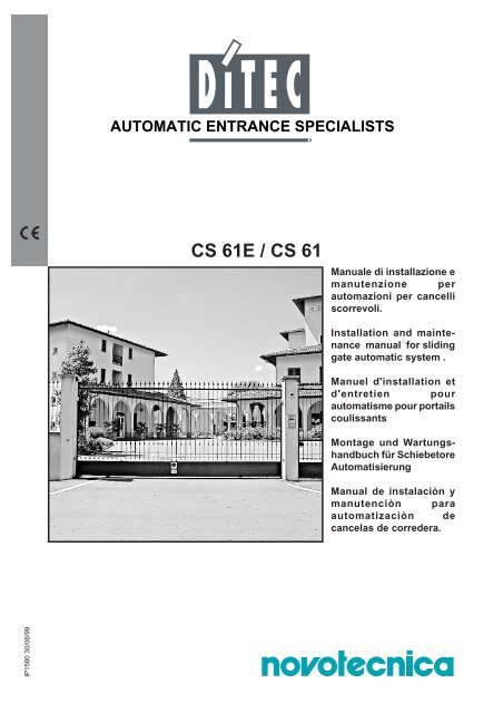
CS 61E / CS 61
CS 61E / CS 61
CS 61E / CS 61

You also want an ePaper? Increase the reach of your titles
YUMPU automatically turns print PDFs into web optimized ePapers that Google loves.
<strong>CS</strong> <strong><strong>61</strong>E</strong> / <strong>CS</strong> <strong>61</strong><br />
Manuale di installazione e<br />
manutenzione per<br />
automazioni per cancelli<br />
scorrevoli.<br />
Installation and maintenance<br />
manual for sliding<br />
gate automatic system .<br />
Manuel d'installation et<br />
d'entretien pour<br />
automatisme pour portails<br />
coulissants<br />
Montage und Wartungshandbuch<br />
für Schiebetore<br />
Automatisierung<br />
Manual de instalaciòn y<br />
manutenciòn para<br />
automatizaciòn de<br />
cancelas de corredera.<br />
IP1580 30/06/99
INDICE<br />
Installazione tipo .............................................................................................................................................. pag. 3<br />
Illustrazioni ....................................................................................................................................................... pag. 4-5<br />
Avvertenze generali per la sicurezza................................................................................................................ pag. 6<br />
Dati tecnici......................................................................................................................................................... pag. 7<br />
Riferimenti illustrazioni .................................................................................................................................... pag. 7<br />
Installazione....................................................................................................................................................... pag. 7<br />
Collegamenti elettrici <strong>CS</strong><strong><strong>61</strong>E</strong> ............................................................................................................................pag. 8<br />
Avviamento........................................................................................................................................................ pag. 9<br />
Collegamenti elettrici <strong>CS</strong><strong>61</strong>.............................................................................................................................. pag. 9<br />
Piano di manutenzione..................................................................................................................................... pag. 9<br />
Ricerca guasti .................................................................................................................................................. pag. 9<br />
Istruzioni d’uso.................................................................................................................................................. pag. 10<br />
INDEX<br />
Standard installation ........................................................................................................................................ page 3<br />
Illustration.......................................................................................................................................................... page 4-5<br />
General safety precautions .............................................................................................................................. page 11<br />
Technical data.................................................................................................................................................... page 12<br />
Reference to illustrations.................................................................................................................................. page 12<br />
Installation..........................................................................................................................................................page 12<br />
Electrical connections <strong>CS</strong><strong><strong>61</strong>E</strong>...........................................................................................................................page 13<br />
Starting-up..........................................................................................................................................................page 14<br />
Electrical connections <strong>CS</strong><strong>61</strong>............................................................................................................................. page 14<br />
Maintenance program........................................................................................................................................page 14<br />
Trouble shooting .............................................................................................................................................. page 14<br />
Operating instruction.........................................................................................................................................page 15<br />
INDEX<br />
Installation type ............................................................................................................................................... page 3<br />
Elements .......................................................................................................................................................... page 4-5<br />
Consignes generales de securité..................................................................................................................... page 16<br />
Donnees tecniques............................................................................................................................................ page 17<br />
Elements....................... .................................................................................................................................... page 17<br />
Installation......................................................................................................................................................... page 17<br />
Raccordement electriques <strong>CS</strong><strong><strong>61</strong>E</strong>.................................................................................................................... page 18<br />
Demarrage......................................................................................................................................................... page 19<br />
Raccordement electriques <strong>CS</strong><strong>61</strong>..................................................................................................................... page 19<br />
Entretien periodique......................................................................................................................................... page 19<br />
Recherche pannes ........................................................................................................................................... page 19<br />
Instructions d’utilisation................................................................................................................................... page 20<br />
ANGABE<br />
Standard Montage ............................................................................................................................................ pag. 3<br />
Abbildungen ..................................................................................................................................................... pag. 4-5<br />
Allgemeine Sicherheitshinweise...................................................................................................................... pag. 21<br />
Technischen Daten............................................................................................................................................ pag. 22<br />
Verweis auf Abbildungen................................................................................................................................. pag. 22<br />
Montage............................................................................................................................................................. pag. 22<br />
Elektrische Anschlüsse <strong>CS</strong><strong><strong>61</strong>E</strong>........................................................................................................................ pag. 23<br />
Anlauf................................................................................................................................................................ pag. 24<br />
Elektrische Anschlüsse <strong>CS</strong><strong>61</strong>.......................................................................................................................... pag. 24<br />
Regelmässige Instandhaltung.......................................................................................................................... pag. 24<br />
Fehlersuche ...................................................................................................................................................... pag. 24<br />
Bedienungsanleitung.........................................................................................................................................pag. 25<br />
INDICE<br />
Installaciòn tipo ................................................................................................................................................ pàg. 3<br />
Elementos ........................................................................................................................................................ pàg. 4-5<br />
Advertencias generales de seguridad............................................................................................................. pàg. 26<br />
Datos tecnicos................................................................................................................................................... pàg. 27<br />
Referencias de las ilustraciones...................................................................................................................... pàg. 27<br />
Installacion........................................................................................................................................................ pàg. 27<br />
Conexiones eléctricas <strong>CS</strong><strong><strong>61</strong>E</strong> .......................................................................................................................... pàg. 28<br />
Arranque ........................................................................................................................................................... pàg. 29<br />
Conexiones eléctricas <strong>CS</strong><strong>61</strong>. .......................................................................................................................... pàg. 29<br />
Mantenimiento.................................................................................................................................................. pàg. 29<br />
Busqueda de averias ....................................................................................................................................... pàg. 29<br />
Instrucciones de uso......................................................................................................................................... pàg. 30<br />
DITEC S.P.A - IP1580 30/06/99 - <strong>CS</strong><strong>61</strong>/<strong>CS</strong><strong><strong>61</strong>E</strong><br />
2
I<br />
UK<br />
F<br />
D<br />
E<br />
Impianto tipo<br />
Standard installation<br />
Installation type<br />
Standard Montage<br />
Instalaciòn tipo<br />
6 6<br />
2<br />
3<br />
5<br />
5<br />
2x1.5 mm²<br />
4x0.5 mm²<br />
RX-4x0.5 mm²<br />
TX - 4x0.5 mm²<br />
4<br />
8<br />
3x1.5 mm²<br />
1<br />
7<br />
Fig. 1<br />
3 DITEC S.P.A - IP1580 30/06/99 - <strong>CS</strong><strong>61</strong>/<strong>CS</strong><strong><strong>61</strong>E</strong>
13 12 11 10<br />
9<br />
20<br />
200 95<br />
315<br />
14<br />
15<br />
110<br />
275<br />
100<br />
200<br />
fig. 2<br />
fig. 3<br />
min. 30<br />
D E F<br />
200<br />
80<br />
max 5 mm<br />
G<br />
130<br />
B<br />
270<br />
fig. 4 fig. 5<br />
DITEC S.P.A - IP1580 30/06/99 - <strong>CS</strong><strong>61</strong>/<strong>CS</strong><strong><strong>61</strong>E</strong><br />
4
H<br />
2÷3<br />
fig. 6 fig. 7<br />
~20<br />
fig. 8<br />
DIP1 OFF<br />
fig. 9 DIP1 ON<br />
fig. 10<br />
<strong>CS</strong><strong>61</strong><br />
M<br />
1~<br />
NERO / BLACK<br />
BLU / BLUE com<br />
BIANCO/WHITE<br />
U<br />
W<br />
V<br />
A<br />
C<br />
16 µF<br />
NERO / BLACK<br />
BLU / BLUE<br />
BIANCO/WHITE<br />
FC1 / 11<br />
COM / 0<br />
FC2 / 12<br />
fig. 11<br />
5 DITEC S.P.A - IP1580 30/06/99 - <strong>CS</strong><strong>61</strong>/<strong>CS</strong><strong><strong>61</strong>E</strong>
GENERAL SAFETY PRECAUTIONS<br />
This installation manual is intended for professionally competent personnel only.<br />
The installation, the electrical connections and the settings must be completed in conformity with good workmanship and<br />
with the laws in force.<br />
Read the instructions carefully before beginning to install the product. Incorrect installation may be a source of danger.<br />
Packaging materials (plastics, polystyrene, etc) must not be allowed to litter the environment and must be kept out of the reach of children<br />
for whom they may be a source of danger.<br />
Before beginning the installation check that the product is in perfect condition.<br />
Do not install the product in explosive areas and atmospheres: the presence of flammable gas or fumes represents a serious threat to<br />
safety.<br />
Before installing the motorisation device, make all the structural modifications necessary in order to create safety clerance and to guard<br />
or isolate all the compression, shearing, trapping and general danger areas.<br />
Check that the existing structure has the necessary strength and stability.<br />
The manufacturer of the motorisation device is not responsible for the non-observance of workmanship in the costruction of the frames to<br />
be motorised , nor for deformations that may be occur during use.<br />
The safety devices (photoelectric cells, mechanical obstruction sensor, emergency stop, etc) must be installed taking into account: the<br />
provisions and the directives in force, good workmanship criteria, the installation area, the funtional logic of the system and the forces<br />
developed by the motorised door or gate.<br />
The safety devices must protect against compression, shearing, trapping and general danger areas of the motorized door or gate.<br />
Display the signs required by law to identify danger areas.<br />
Each installation must bear a visible indication of the data identifying the motorised door or gate.<br />
Before connecting to the mains check that the rating is correct for the destination power requirements.<br />
A multipolar isolation switch with minimum contact gaps of 3 mm must be included in the mains supply.<br />
Check that upstream of the electrical installation there is an adequate differential switch and a suitable circuit breaker.<br />
Ensure that the motorised door or gate has an earth terminal in accordance with the safety regulations in force.<br />
The manufacturer of the motorising device declines all responsability in cases where components which are incompatible with the safe<br />
and correct operation of the product only original spare parts must be used.<br />
For repairs or replacements of products only original spare parts must be used.<br />
The fitter must supply all information corcerning the automatic, the manual and emergency operation of the motorised door or gate, and<br />
must provide the user the device with the operating instructions.<br />
MACHINERY DIRECTIVE<br />
Pursuant to Machinery Directive (98/37/EC) the installer who motorises a door or gate has the same obligations as the manufacturer of<br />
machinery and as such must:<br />
- prepare the technical file which must contain the documents indicated in Annex V of the Machinery Directive; (The technical file must<br />
be kept and placed at the disposal of competent national authorities for at least ten years from the date of manufacture of the<br />
motorised door);<br />
- draft the EC declaration of conformity in accordance with Annex II-A of the Machinery Directive;<br />
- affix the CE marking on the power operated door in accordance with point 1.7.3 of Annex I of the Machinery Directive.<br />
For more information consult the “Technical Manual Guidelines” available on Internet at the following address: http://www.seisnet.it/ditec/<br />
ENGLISH<br />
APPLICATIONS<br />
Maximum permissible weight: 600 kg<br />
Recommended weight: 400<br />
Service life: 3 (minimum 10÷5 years of working life with 30÷60 cycles a day)<br />
Applications: FREQUENT (For vehicle or pedestrian accesses to town houses or small condominiums with frequent use).<br />
Minimum number of consecutive cycles: 15<br />
• Performance characteristics are to be understood as referring to the recommended weight (approx. 2/3 of maximum permissible<br />
weight). A reduction in performance is to be expected when the access is made to operate at the maximum permissible weight.<br />
• Service class, running times, and the number of consecutive cycles are to be taken as merely indicative having been statistically<br />
determined under average operating conditions, and are therefore not necessarily applicable to specific conditions of use. During<br />
given time spans product performance characteristics will be such as not to require any special maintenance.<br />
• The actual performance characteristics of each automatic access may be affected by independent variables such as friction, balancing<br />
and environmental factors, all of which may substantially alter the performance characteristics of the automatic access or curtail its<br />
working life or parts thereof (including the automatic devices themselves). When setting up, specific local conditions must be duly<br />
borne in mind and the installation adapted accordingly for ensuring maximum durability and trouble-free operation.<br />
DECLARATION BY THE MANUFACTURER<br />
(Directive 98/37/EC, Annex II, sub B)<br />
Manufacturer: DITEC S.p.A.<br />
Address: via Mons. Banfi, 3 - 21042 Caronno Pertusella (VA) - ITALY<br />
Herewith declares that the electromechanical automatic system series <strong>CS</strong><strong><strong>61</strong>E</strong>-<strong>CS</strong><strong>61</strong><br />
- is intended to be incorpored into machinery or to be assembled with other machinery to constitute machinery convered by Directive<br />
98/37/EC, as amended;<br />
- is in conformity with the provisions of the following other EEC directives:<br />
Electromagnetic Compatibility Directive 89/336/EEC, as amended;<br />
Low Voltage Directive 73/23/EEC, as amended;<br />
and furthermore declares that it is not allowed to put the machinery into service until the machinery into which it is to be incorporated or<br />
of which it is to be a component has been found and declared to be in conformity with the provisions of Directive 98/37/EC and with<br />
national implementing legislation.<br />
Caronno Pertusella, 03/06/1999. Fermo Bressanini<br />
(Chairman)<br />
11 DITEC S.P.A - IP1580 30/06/99 - <strong>CS</strong><strong>61</strong>/<strong>CS</strong><strong><strong>61</strong>E</strong>
1. TECHNICAL DATA<br />
Power supply<br />
230 V~ 50 Hz<br />
Absorption<br />
2 A<br />
Motor power<br />
250 W<br />
Torque<br />
700 N<br />
Max. run<br />
13 m<br />
Max. door weight<br />
600 kg<br />
Speed<br />
0.18 m/s<br />
Intermittence S2 = 15 min. / S3 = 25%<br />
Temperature -15 °C / +50 °C<br />
Degree of protection<br />
IP54<br />
Weight<br />
12.7 kg<br />
2. REFERENCE TO ILLUSTRATIONS<br />
2.1 Standard installation references (fig. 1)<br />
ATTENTION: Only use DITEC’s safety devices and accessories for installation.<br />
ENGLISH<br />
1 Radio<br />
2 Flashing light<br />
3 Key selector<br />
7 Rubber hip / Sensitive hip<br />
4 Connect power supply to an omni-pole switch with a contact opening gap of no less that 3 mm (not supplied<br />
by us)<br />
2.2 Geared motor references (fig. 2)<br />
9 Geared motor<br />
10 Carter<br />
11 Release access door<br />
12 Release<br />
5 Geared motor + Electrical board<br />
6 Photocells<br />
13 Electrical board<br />
14 Limit-switch spring<br />
15 Pinion<br />
8 Opening and closing stop<br />
3. INSTALLATION<br />
3.1 Preliminary checks<br />
Check for gate stability and that the slide wheels are in good condition and the top guides do not cause any<br />
friction. The slideway must be securely anchored to the ground and fully exposed along its full length. It must be<br />
perfectly smooth so as to avoid jamming of the gate.<br />
Provide an opening and closing stop.<br />
Make sure that the gate is securely inserted in the slideway so that it cannot come out of the<br />
slideway and fall.<br />
Geared motor installation<br />
Unless otherwise specified, all measurements are expressed in millimetres.<br />
3.2 (Fig. 4) Lay a concrete foundation with buried anchoring brackets and the base plate, making sure that it is<br />
pefectly level and smooth. Allow for 80 mm between the plate axis and the rack B . Route the cable ducts<br />
through the two holes in the middle of the plate.<br />
3.3 (Fig. 5) Open the release access door 11 , loosen the screw that locks the carter and lift it. Insert the<br />
ancoring feet G at the gear motor base. Position the geared motor on to the base plate. Adjusting<br />
gearmotor: horizontally by sliding in the ancoring feet notches, vertically with the 4 levelling screws D :<br />
while adjusting vertically, keep the motor slightly raised above the base plate so as to allow enough<br />
space to secure the rack and to make any subsequent adjustments, if necessary.<br />
3.4 (Fig. 6) Secure the rack by disengaging the geared motor and opening the gate. Place the rack on pinion<br />
15 and move the gate manually to secure the rack along its full length. Once the rack has been secured,<br />
vertically adjust the geared motor so as to have a gap of 2 to 3 mm between the pinion and the rack. Finally,<br />
firmly secure the geared motor by fitting shims E and washers F .<br />
3.5 (Fig. 7, 8) Adjusting limit switch: secure the limit stop skids H on to the rack so that the gate stops about<br />
20 mm before reaching the stop.<br />
DITEC S.P.A - IP1580 30/06/99 - <strong>CS</strong><strong>61</strong>/<strong>CS</strong><strong><strong>61</strong>E</strong><br />
12
4. ELECTRICAL CONNECTIONS <strong>CS</strong><strong><strong>61</strong>E</strong><br />
CONTROL BOARD<br />
F1<br />
F2<br />
FC2<br />
Limit switch<br />
COM<br />
Release micro<br />
FC1<br />
Limit switch<br />
RF TC R1<br />
DIP1<br />
Q.E. D<strong>61</strong><br />
ON<br />
OFF<br />
L N UWV 1211 0 1 5 6 8 9<br />
com<br />
230 V~<br />
M<br />
1 ~<br />
16 µF<br />
- +<br />
24 V / 0.15 A<br />
F1 = F5 A line<br />
F2 = F315 mA accessories<br />
ENGLISH<br />
4.1 Controls<br />
WARNING:<br />
CONTACT FUNCTION DESCRIPTION<br />
Link up all N.C. contacts (if not used) by means of jumpers.<br />
The terminal bearing the same number are equivalent.<br />
1 5 (N.O.) STEP BY STEP With TC at maximum: “open-stop-close” sequence.<br />
With TC not at maximum: “open-close/automatic<br />
closure” sequence. The closing control can operate<br />
when the gate is standing opened.<br />
1 6 (N.C.) STOP SAFETY It stops and/or prevents any movement.<br />
CONTACT<br />
1 8 (N.C.) REVERSAL SAFETY Reverses movement (re-opens) during closing.<br />
CONTACT<br />
When door is not moving, inhibits all operation.<br />
1 9 (N.C.) EMERCENCY By opening the 1-9 contact the gate stops or remains<br />
STOP<br />
still and the automatic closing is disabled.<br />
REMOTE CONTROL STEP BY STEP It has the same function as the 1-5 control.<br />
Parallel connection<br />
of automatic controls<br />
This model does not permit the running of two motors<br />
in parallel.<br />
4.2. Output and accessories<br />
1 + Accessories power supply. 24V / 0.15A (nominal) / 0.3 A (peak) output<br />
0 - for powering of external accessories including gate state lamp.<br />
1 11 Lamp (24 V / 1.5 W) gate open with DIP1 ON, closed gate lamp with<br />
DIP1 OFF.<br />
1 12 Lamp (24 V / 1.5 W) gate close with DIP1 OFF, open gate lamp with<br />
DIP1 ON.<br />
W N Flashing light. 230 V~/ 100 W max. output. It is lighting during the opening<br />
and closing operation. With automatic closure mode the flashing begins<br />
3 s before the end of the setted time of TC, with TC lesser 3 s the flashing<br />
lasts as long as the break time.<br />
13 DITEC S.P.A - IP1580 30/06/99 - <strong>CS</strong><strong>61</strong>/<strong>CS</strong><strong><strong>61</strong>E</strong>
4.3 Setting and adjustments<br />
TC - Automatic closure time. From 0 to 120 s, with TC from 0 to 3/4 turn. The counting begins:<br />
- at the end of the opening operation and lasts as long as the time set on the TC trimmer;<br />
- after a safety device has operated (1-6 / 1-8) and lasts half the time set on the TC.<br />
TC at maximum disable the automatic closure. Warning: the position of TC (which enables or disables automatic<br />
closing ) also selects the function of control 1-5.<br />
RF - Power adjustment. Setting of RF from min to max selects min to max power. The motor always starts up<br />
at max power and after 1 s switches over to the power set via RF.<br />
R1 - Obstacle detection adjustment. The electric board is fitted with a safety device which, in case of an<br />
obstacle being detected, causes the gate to stop moving when it is opening and to reverse movement when it is<br />
closing. With trimmer R1 at minimum there is maximum sensitivity. With R1 at maximum the function is cut out.<br />
DIP1 - Selection of movement direction OFF = opening toward the right, ON = opening toward the left (see<br />
fig. 9 and 10).<br />
5. STARTING UP<br />
WARNING: the operations regarding point 5.2 are without safety devices.<br />
the trimmer can only be adjusted with gate not moving (RF excluded).<br />
ENGLISH<br />
5.1. Set TC, RF and R1 at maximum. Short circuit the safety devices and the stop device. Select desired<br />
movement direction by means of DIP1 (see fig. 9 and 10).<br />
5.2. Power and check the gate functions correctly with a sequence of step-by-step commands. Check the action<br />
of the limit switches.<br />
5.3. Remove the jumpers and connect the safety devices (1-6 and 1-8) and the stop (1-9). Check their function.<br />
5.4. Adjust the automatic closure with TC. Warning: the automatic closure time after the operation of one of<br />
the safety devices is half the set time.<br />
5.5. Put RF in the position which ensures functioning and the safety of the user.<br />
5.6. After having set RF, set the obstacle detection sensitivity with R1.<br />
5.7. Connect any accessories and check their function.<br />
5.8. Re-fit the casing and make sure that the stop microswitch tripped by release door 11 is properly operating.<br />
6. ELECTRICAL CONNECTION <strong>CS</strong><strong>61</strong><br />
Connect the motor and limit switches to the control panel as in figure 11. A and C refer to opening and closing<br />
limit switch.<br />
7. TROUBLE SHOOTING<br />
PROBLEM<br />
Gate fails to open and close.<br />
Gate opens but fails to close.<br />
External safeties fail to trigger.<br />
Flashing light not work.<br />
POSSIBLE CAUSE<br />
Power failure.<br />
F1/F2 fuse blown.<br />
Safety contacts open.<br />
Geared motor released.<br />
Radio control not working.<br />
Safety contacts open.<br />
Photocells activated.<br />
Automatic closure not working.<br />
Incorrect wiring between photocells and the<br />
Electric Board.<br />
Bulb blown.<br />
REMEDY<br />
Check for power supply from mains.<br />
Change fuse.<br />
Check terminals 6, 8 and 9 in the E. B.<br />
Check that release door is locked and that<br />
release microswitch is pressed.<br />
Check for proper installation and activation of<br />
the radio device (TX and RX).<br />
Check terminal 8 of the E.B.<br />
Check that photocells are clean and properly<br />
working<br />
Check that TC trimmer is not set to maximum.<br />
Connect N.C. safety contact in series and<br />
remove any jumpers.<br />
Replace with a 230 V bulb.<br />
8. MAINTENANCE PROGRAM (each 6 month)<br />
Power off (230 V~ mains and batteries, if installed)<br />
- Check gate/gear motor alignment and the distance (2-3 mm) between the mouth of the pinion and the crest of the rack.<br />
- Clean the wheel slideways, the rack and the pinion of the geared motor.<br />
Power on (230 V~ mains and batteries)<br />
- Check the functioning of the limit switches (the gate must come to a halt ~ 20 mm before the stop)<br />
- Check the power adjustments.<br />
- Check the operation of all command and safety functions (photocells).<br />
ATTENTION: For spare parts, see the spares price list.<br />
DITEC S.P.A - IP1580 30/06/99 - <strong>CS</strong><strong>61</strong>/<strong>CS</strong><strong><strong>61</strong>E</strong><br />
14
TEAR OFF AND DELIVER TO USER<br />
Operating instruction <strong>CS</strong><strong><strong>61</strong>E</strong>, <strong>CS</strong><strong>61</strong><br />
Automation for sliding gates<br />
ENGLISH<br />
RELEASE INSTRUCTION<br />
In case of faulty operation or power failure, insert and rotate the key anticlockwise. Open the door and rotate the<br />
release knob anticlockwise. Manually slide the gate open<br />
To re-lock the gate, rotate the knob clockwise without tightening, slightly move the gate and finally fully tighten<br />
down the knob. To return to automatic mode, lock the door with the key.<br />
WARNING: If the door is opened, the limit switch common is opened thus preventing all operations.<br />
GENERAL SAFETY PRECAUTIONS<br />
The following precautions are an integral and essential part of the product and must be supplied to the user.<br />
Read them carefully as they contain important indications for the safe installation, use and maintenace.<br />
These instruction must be kept and forwarded to all possible future user of the system. This product must be used only for that which it has<br />
been expressely designed. Any other use is to be considered improper and therefore dangerous.<br />
The manufacturer cannot be held responsible for possible damage caused by improper, erroneous or unresonable use.<br />
Avoid operating in the proximity of the hinges or moving mechanical parts. Do not enter the field of action of the motorised door or gate<br />
while in motion. Do not obstruct the motion of the motorised door or gate as this may cause a situation of danger.<br />
Do not lean against or hang on to the barrier when it is moving.<br />
Do not allow children to play or stay within the field of action of the motorised door or gate.<br />
Keep remote control or any other control devices out of the reach of children, in order to avoid possible involuntary activation of the<br />
motorised door or gate. In case of breack down or malfunctioning of the product, disconnect from mains, do not attempt to repair or<br />
intervene directly and contact only qualified personnel. Failure to comply with the above may create a situation of danger.<br />
All cleaning, maintenance or repair work must be carried out by qualified personnel.<br />
In order to guarantee that the system works efficiently and correctly it is indispensable to comply with the manufacturer’s indications thus<br />
having the periodic maintenance of the motorised door or gate carried out by qualified personnel.<br />
In particular regular checks are recommended in order to verify that the safety devices are operating correctly.<br />
All installation, maintenance and repair work must be documented and made available to the user.<br />
DITEC S.p.A.<br />
Via Mons. Banfi, 3<br />
21042 Caronno P.lla (VA) Italy<br />
Tel.02/963911 - Fax 02/9650314<br />
www.ditec.it<br />
ISO 9001 - Cert. n° 0957/0