Fan Coil Unit - Enviro-Tec
Fan Coil Unit - Enviro-Tec
Fan Coil Unit - Enviro-Tec

You also want an ePaper? Increase the reach of your titles
YUMPU automatically turns print PDFs into web optimized ePapers that Google loves.
~~~~~~~~~~~~~~~~~~~~~~~~~~~~~~~~~~<br />
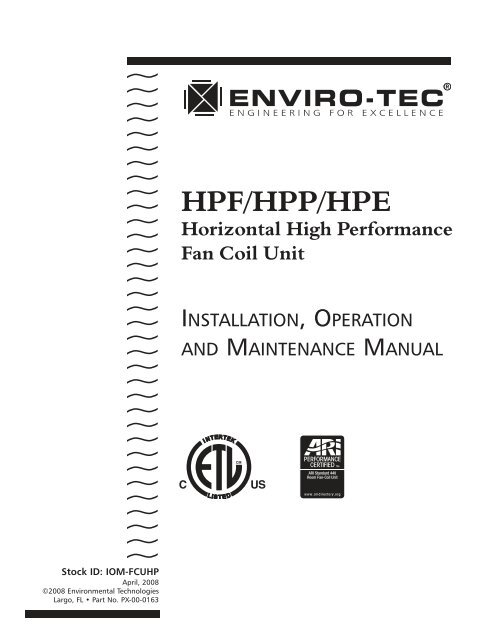
HPF/HPP/HPE<br />
Horizontal High Performance<br />
<strong>Fan</strong> <strong>Coil</strong> <strong>Unit</strong><br />
INSTALLATION, OPERATION<br />
AND MAINTENANCE MANUAL<br />
Stock ID: IOM-FCUHP<br />
April, 2008<br />
©2008 <strong>Enviro</strong>nmental <strong>Tec</strong>hnologies<br />
Largo, FL • Part No. PX-00-0163
HP FAN COIL • TABLE OF CONTENTS<br />
DESCRIPTION<br />
PAGE NUMBER(S)<br />
Important Safety Precautions . . . . . . . . . . . . . . . . . . . . . . . . . . . . . . . . . . . . . . . . . . . . . . . . . . 3<br />
HP Series Features . . . . . . . . . . . . . . . . . . . . . . . . . . . . . . . . . . . . . . . . . . . . . . . . . . . . . . . . . . . 4<br />
SECTION ONE: Receipt & Initial Installation<br />
Preface. . . . . . . . . . . . . . . . . . . . . . . . . . . . . . . . . . . . . . . . . . . . . . . . . . . . . . . . . . . . . . . . . 4<br />
Unpacking & Inspection . . . . . . . . . . . . . . . . . . . . . . . . . . . . . . . . . . . . . . . . . . . . . . . . . . . 5<br />
Handling & Installation . . . . . . . . . . . . . . . . . . . . . . . . . . . . . . . . . . . . . . . . . . . . . . . . . . . . 6<br />
Drain Pan. . . . . . . . . . . . . . . . . . . . . . . . . . . . . . . . . . . . . . . . . . . . . . . . . . . . . . . . . . . . . . . 6<br />
Auxiliary Drain Pans . . . . . . . . . . . . . . . . . . . . . . . . . . . . . . . . . . . . . . . . . . . . . . . . . . . . . . . 6<br />
Condensate Trap . . . . . . . . . . . . . . . . . . . . . . . . . . . . . . . . . . . . . . . . . . . . . . . . . . . . . . . . . 7<br />
Return Air . . . . . . . . . . . . . . . . . . . . . . . . . . . . . . . . . . . . . . . . . . . . . . . . . . . . . . . . . . . . . . 7<br />
<strong>Fan</strong> Removal . . . . . . . . . . . . . . . . . . . . . . . . . . . . . . . . . . . . . . . . . . . . . . . . . . . . . . . . . . . . 7<br />
Plenum Box Service Panel . . . . . . . . . . . . . . . . . . . . . . . . . . . . . . . . . . . . . . . . . . . . . . . . . . 7<br />
Plenum Box Removal . . . . . . . . . . . . . . . . . . . . . . . . . . . . . . . . . . . . . . . . . . . . . . . . . . . . . . 8<br />
<strong>Coil</strong> Handing . . . . . . . . . . . . . . . . . . . . . . . . . . . . . . . . . . . . . . . . . . . . . . . . . . . . . . . . . . . . 8<br />
<strong>Coil</strong>s. . . . . . . . . . . . . . . . . . . . . . . . . . . . . . . . . . . . . . . . . . . . . . . . . . . . . . . . . . . . . . . . . . . 8<br />
Piping Connections . . . . . . . . . . . . . . . . . . . . . . . . . . . . . . . . . . . . . . . . . . . . . . . . . . . . . . . 8<br />
Ductwork Connections . . . . . . . . . . . . . . . . . . . . . . . . . . . . . . . . . . . . . . . . . . . . . . . . . . . . 9<br />
Electrical Connections . . . . . . . . . . . . . . . . . . . . . . . . . . . . . . . . . . . . . . . . . . . . . . . . . . . . . 9<br />
Control Enclosure . . . . . . . . . . . . . . . . . . . . . . . . . . . . . . . . . . . . . . . . . . . . . . . . . . . . . . . . 9<br />
Telescoping Bottom Panel. . . . . . . . . . . . . . . . . . . . . . . . . . . . . . . . . . . . . . . . . . . . . . . . . . 10<br />
SECTION TWO: Start-Up<br />
General. . . . . . . . . . . . . . . . . . . . . . . . . . . . . . . . . . . . . . . . . . . . . . . . . . . . . . . . . . . . . . . . 10<br />
Cooling/Heating . . . . . . . . . . . . . . . . . . . . . . . . . . . . . . . . . . . . . . . . . . . . . . . . . . . . . . . . . 10<br />
Motor & <strong>Fan</strong> Data. . . . . . . . . . . . . . . . . . . . . . . . . . . . . . . . . . . . . . . . . . . . . . . . . . . . . . . . 11<br />
ARI Standard Ratings . . . . . . . . . . . . . . . . . . . . . . . . . . . . . . . . . . . . . . . . . . . . . . . . . . . . . 11<br />
Air System Balancing . . . . . . . . . . . . . . . . . . . . . . . . . . . . . . . . . . . . . . . . . . . . . . . . . . . . . 12<br />
Water System Balancing . . . . . . . . . . . . . . . . . . . . . . . . . . . . . . . . . . . . . . . . . . . . . . . . . . . 12<br />
Controls Operation . . . . . . . . . . . . . . . . . . . . . . . . . . . . . . . . . . . . . . . . . . . . . . . . . . . . . . . 12<br />
SECTION THREE: Normal Operation & Periodic Maintenance, Physical Data<br />
General. . . . . . . . . . . . . . . . . . . . . . . . . . . . . . . . . . . . . . . . . . . . . . . . . . . . . . . . . . . . . . . . 12<br />
Motor/Blower Assembly . . . . . . . . . . . . . . . . . . . . . . . . . . . . . . . . . . . . . . . . . . . . . . . . . . . 13<br />
<strong>Fan</strong> Assembly . . . . . . . . . . . . . . . . . . . . . . . . . . . . . . . . . . . . . . . . . . . . . . . . . . . . . . . . . . . 13<br />
<strong>Coil</strong> . . . . . . . . . . . . . . . . . . . . . . . . . . . . . . . . . . . . . . . . . . . . . . . . . . . . . . . . . . . . . . . . . . . 13<br />
Electric Resistance Heater Assembly . . . . . . . . . . . . . . . . . . . . . . . . . . . . . . . . . . . . . . . . . . 13<br />
<strong>Unit</strong> Weight Data . . . . . . . . . . . . . . . . . . . . . . . . . . . . . . . . . . . . . . . . . . . . . . . . . . . . . . . . 14<br />
Electrical Wiring & Controls . . . . . . . . . . . . . . . . . . . . . . . . . . . . . . . . . . . . . . . . . . . . . . . . 14<br />
Electric Heat Selection Chart. . . . . . . . . . . . . . . . . . . . . . . . . . . . . . . . . . . . . . . . . . . . . . . . 15<br />
Wiring Diagrams. . . . . . . . . . . . . . . . . . . . . . . . . . . . . . . . . . . . . . . . . . . . . . . . . . . . . . . . . 16<br />
Valves & Piping. . . . . . . . . . . . . . . . . . . . . . . . . . . . . . . . . . . . . . . . . . . . . . . . . . . . . . . . . . 18<br />
Filters . . . . . . . . . . . . . . . . . . . . . . . . . . . . . . . . . . . . . . . . . . . . . . . . . . . . . . . . . . . . . . . . . 18<br />
Drain. . . . . . . . . . . . . . . . . . . . . . . . . . . . . . . . . . . . . . . . . . . . . . . . . . . . . . . . . . . . . . . . . . 18<br />
Face Area, Free Area, Filter Sizes. . . . . . . . . . . . . . . . . . . . . . . . . . . . . . . . . . . . . . . . . . . . . 19<br />
Replacement Parts . . . . . . . . . . . . . . . . . . . . . . . . . . . . . . . . . . . . . . . . . . . . . . . . . . . . . . . 19<br />
Dimensional Data: HPF, HPP, HPE, HPM . . . . . . . . . . . . . . . . . . . . . . . . . . . . . . . . . . . . . . . 20<br />
Dimensional Data: HP Telescoping / Filter and Solid Bottom Access Panels . . . . . . . . . . . . 26<br />
<strong>Coil</strong> Connection Sizes . . . . . . . . . . . . . . . . . . . . . . . . . . . . . . . . . . . . . . . . . . . . . . . . . . . . . 27<br />
ECM Motor <strong>Fan</strong> Calibration . . . . . . . . . . . . . . . . . . . . . . . . . . . . . . . . . . . . . . . . . . . . . . . . 28<br />
ECM Motor Balancing Instructions . . . . . . . . . . . . . . . . . . . . . . . . . . . . . . . . . . . . . . . . . . . 29<br />
SECTION FOUR: Inspection & Start-Up Checklist . . . . . . . . . . . . . . . . . . . . . . . . . . . . . . . . . 30<br />
Information subject to change without notice. Visit www.enviro-tec.com for current IOM Manuals and submittal drawings.<br />
2<br />
©April, 2008 <strong>Enviro</strong>nmental <strong>Tec</strong>hnologies
I.O.M. MANUAL • HP FAN COIL<br />
SAFETY CONSIDERATIONS<br />
The equipment covered by this manual is designed for safe and reliable operation when installed and operated<br />
within its design specification limits. To avoid personal injury or damage to equipment or property<br />
while installing or operating this equipment, it is essential that qualified, experienced personnel perform<br />
these functions using good judgement and safe practices. See the following cautionary statements.<br />
DANGER<br />
ELECTRICAL SHOCK HAZARDS. All power must be disconnected prior to installation and serving this equipment.<br />
More than one source of power may be present. Disconnect all power sources to avoid electrocution<br />
or shock injuries.<br />
MOVING PARTS HAZARDS. Motor and Blower must be disconnected prior to opening access panels. Motors<br />
can start automatically, disconnect all power and control circuits prior to servicing to avoid serious crushing<br />
or dismemberment injuries.<br />
HOT PARTS HAZARD. Electric Resistance heating elements must be disconnected prior to servicing. Electric<br />
Heaters may start automatically, disconnect all power and control circuits prior to servicing to avoid burns.<br />
WARNING<br />
Check that the unit assembly and component weights can be safely supported by rigging and lifting equipment.<br />
All assemblies must be adequately secured during lifting and rigging by temporary supports and restraints<br />
until equipment is permanently fastened and set in its final location.<br />
All unit temporary and permanent supports must be capable of safely supporting the equipment's weight<br />
and any additional live or dead loads that may be encountered. All supports must be designed to meet<br />
applicable local codes and ordinances.<br />
All fastening devices must be designed to mechanically lock the assembly in place without the capability<br />
of loosening or breaking away due to system operation and vibration.<br />
CAUTION<br />
Protect adjacent flammable materials when brazing, Use flame and heat protection barriers where needed.<br />
Have fire extinguisher available and ready for immediate use.<br />
CODE COMPLIANCE<br />
This equipment has been manufactured and certified in accordance with UL 1995-Standard for Safety,<br />
Heating and Cooling Equipment (CAN/CSA C22.2 NO 236-M90) and bears the Electrical Testing Laboratories<br />
(ETL) Mark under ETL File No: 3036742-002.<br />
©April, 2008 <strong>Enviro</strong>nmental <strong>Tec</strong>hnologies<br />
3
HP FAN COIL • I.O.M. MANUAL<br />
HP SERIES<br />
(HPP Plenum Return Shown)<br />
SECTION ONE: Receipt & Initial Installation<br />
PREFACE<br />
<strong>Enviro</strong>nmental <strong>Tec</strong>hnologies fan coils represent a prudent investment which can, with proper installation,<br />
operation, and regular maintenance, give trouble-free operation and long service.<br />
Your equipment is initially protected under the manufacturer’s standard warranty; however, this<br />
warranty is provided under the condition that the steps outlined in this manual for initial<br />
inspection, proper installation, regular periodic maintenance, and everyday operation of the<br />
equipment be followed in detail. This manual should be fully reviewed in advance of any actual<br />
work being done on the equipment. Should any questions arise, please contact your local Sales<br />
Representative or the factory BEFORE proceeding.<br />
The equipment covered by this manual is available with a vast variety of options and accessories. Consult<br />
the approved unit submittal, order acknowledgement, and other manuals for details on the options and<br />
accessories provided with the equipment on each project.<br />
4<br />
©April, 2008 <strong>Enviro</strong>nmental <strong>Tec</strong>hnologies
I.O.M. MANUAL • HP FAN COIL<br />
NO ATTEMPT SHOULD BE MADE TO HANDLE, INSTALL, OR SERVICE ANY UNIT<br />
WITHOUT FOLLOWING SAFE PRACTICES REGARDING MECHANICAL EQUIPMENT.<br />
• All power must be disconnected before any installation or service should be attempted. More than one<br />
power source may be supplied to a unit. Power to remote mounted control devices may not be<br />
supplied through the unit. Never wear bulky or loose fitting clothing when working on any mechanical<br />
equipment. Gloves should only be worn when required for proper protection from heat or other<br />
possible injury. Safety glasses or goggles should always be worn when drilling, cutting, or working with<br />
chemicals such as refrigerants or lubricants.<br />
• Never pressurize any equipment beyond specified operating pressures. Always pressure test with some<br />
inert fluid or gas such as clear water or dry nitrogen to avoid possible damage or injury in the event of<br />
a leak or component failure during testing.<br />
• Always protect adjacent flammable material when welding or soldering. Use suitable heat shield material<br />
to contain sparks or drops of solder. Have fire extinguisher available for use when welding or brazing.<br />
The manufacturer assumes no responsibility for personal injury or property damage resulting from improper<br />
or unsafe practices during the handling, installation, service, or operation of any equipment.<br />
UNPACKING & INSPECTION<br />
All units are carefully inspected at the factory throughout the manufacturing process under a strict detailed<br />
quality assurance program, and where possible, all major components and subassemblies are carefully<br />
tested for proper operation and verified to be in full compliance with the factory manufacturing<br />
documents. Customer furnished components such as control valves, switches and DDC controls are not<br />
factory tested.<br />
Each unit is carefully packaged for shipment to avoid damage during normal transport and handling. The<br />
equipment should always be stored in a dry place in the proper orientation as marked on the carton.<br />
All shipments are made F.O.B. factory and it is the responsibility of the receiving party to inspect the<br />
equipment upon arrival. Any obvious damage to the carton and/or its contents should be recorded on the<br />
bill of lading and a claim should be filed with the freight carrier.<br />
After determining the condition of the carton exterior, carefully remove each unit from the<br />
carton and inspect for hidden damage. At this time check to make sure that “furnished only” items such<br />
as switches, thermostats, etc. are accounted for. Any hidden damage should be recorded and immediately<br />
reported to the carrier and a claim filed as before. In the event a claim for shipping damage is filed,<br />
the unit, shipping carton, and all packing must be retained for physical inspection by the freight carrier.<br />
All equipment should be stored in the factory-shipping carton with internal packing in place until<br />
installation.<br />
At the time of receipt, the equipment type and arrangement should be verified against the order documents.<br />
Should any discrepancy be found, the local Sales Representative should be notified immediately<br />
so that the proper action may be instituted. Should any question arise concerning warranty repairs, the<br />
factory must be notified BEFORE any corrective action is taken. Where local repairs or alterations can be<br />
accomplished, the factory must be fully informed as to the extent and expected cost of those repairs before<br />
work is begun. Where factory operations are required, the factory must be contacted for authorization to<br />
return equipment and a Return Authorization Number will be issued. Unauthorized return shipments of<br />
equipment and shipments not marked with an authorization number will be refused. In addition, the manufacturer<br />
will not accept any claims for unauthorized expenses.<br />
©April, 2008 <strong>Enviro</strong>nmental <strong>Tec</strong>hnologies<br />
5
HP FAN COIL • I.O.M. MANUAL<br />
HANDLING & INSTALLATION<br />
While all equipment is designed for durability and fabricated for sturdy construction and may present a<br />
rugged appearance, great care must be taken to assure that no force or pressure be applied to the coil,<br />
piping or drain stub-outs during handling. Also, depending on the options and accessories, some units<br />
could contain delicate components that may be damaged by improper handling. Wherever possible, all<br />
units should be maintained in an upright position and handled by the chassis as close as possible to the<br />
mounting point locations.<br />
In the case of a full cabinet unit, the unit must obviously be handled by the exterior casing. This is acceptable<br />
providing the unit is again maintained in an upright position and no impact forces are applied that<br />
may damage internal components, access panels, or painted surfaces. The equipment covered in this manual<br />
IS NOT suitable for outdoor installations or hazardous/explosive environments. The equipment should<br />
never be stored or installed where it may be subjected to a hostile environment such as rain, snow, extreme<br />
temperatures, corrosive or chemical laden atmospheres.<br />
During and after installation, special care must be taken to prevent foreign material such as paint,<br />
plaster, and drywall dust from being deposited in the drain pan or on the motor or blower wheels. Failure<br />
to do so may have serious adverse effects on unit operation and in the case of the motor and blower assembly,<br />
may result in immediate or premature failure. All manufacturers’ warranties are void if foreign material<br />
is allowed to be deposited on the motor or blower wheels of any unit. Some units and/or job conditions<br />
may require some form of temporary covering during construction.<br />
While the manufacturer does not become involved in the design and selection of support methods and<br />
components, it should be noted that unacceptable system operating characteristics and/or performance<br />
might result from improper or inadequate unit structural support. In addition, adequate clearance must<br />
be provided for service and removal of the equipment and its accessory components. Anchoring the equipment<br />
in place is accomplished by using the mounting points provided and positioning the unit to maintain<br />
the unit on a LEVEL plane. All units are supplied with hanging holes for use with all thread rods.<br />
DRAIN PAN<br />
The optional sloped, insulated drain pan can be equipped with<br />
a secondary drain connection. Standard drain pans are externally<br />
insulated, single wall galvanized steel. The drain pan is easily<br />
removable for cleaning. The pan can be turned around 180<br />
degrees for drainage on the opposite side of the valve package(s)<br />
while capturing condensate from both the coil and the valve package(s).<br />
The optional auxiliary drip pan to catch condensed<br />
moisture from valves and piping is easily attachable to the drain<br />
pan. The drain pan is equipped with external slots and is to be<br />
sloped toward the outlet connection prior to start-up. Care must<br />
be taken to insure that the unit drain pan does not slope away<br />
from the outlet connection.<br />
AUXILIARY DRAIN PANS<br />
The auxiliary drain pan mounts directly to the unit drain pan using<br />
(2) #10 x 1/2" screws.<br />
After the connections are completed, the system should then be<br />
tested for leaks. Since some components are not designed to hold<br />
pressure with a gas, hydronic systems should be tested with water.<br />
6<br />
©April, 2008 <strong>Enviro</strong>nmental <strong>Tec</strong>hnologies
I.O.M. MANUAL • HP FAN COIL<br />
Caution: All water coils must be protected from freezing after initial filling with water. Even if the<br />
system is drained, unit coils may still hold enough water to cause damage when exposed to<br />
temperatures below freezing.<br />
Refrigerant systems should be tested with dry nitrogen rather than air to prevent the introduction of moisture<br />
into the system. In the event that leaking or defective components are discovered, the Sales Representative<br />
must be notified BEFORE any repairs are attempted. All leaks should be repaired before proceeding with<br />
the installation.<br />
Condensate Trap<br />
After system integrity has been established the piping should be insulated<br />
in accordance with the project specifications. ALL chilled water<br />
piping and valves or refrigerant suction piping not located over drain<br />
pans must be insulated to prevent damage from sweating. This<br />
includes factory and field piping inside the unit cabinet.<br />
The drain should always be connected and piped to an acceptable<br />
disposal point. For proper moisture carry-off, the drain piping should<br />
be sloped away from the unit at least 1/8" per foot. A drain trap may<br />
be required by local codes and it is strongly recommended for odor<br />
containment.<br />
Trap detail for positive cabinet<br />
static pressure<br />
RETURN AIR LOCATION<br />
This unit is equipped with a field reversible rear or bottom ducted air return for plenum style units. To<br />
change the return air location, remove the reversible plenum box panel and the filter rack. Rotate both<br />
the reversible panel and filter rack 180 degrees. Replace the reversible panel in the old filter rack position<br />
and fasten using the supplied screws. Fasten the filter rack to the location where the reversible panel was<br />
and replace the filter(s) as described above.<br />
Rear Return<br />
Bottom Return<br />
FAN REMOVAL<br />
This fan assembly is easily removable by unscrewing the (4) ¼-20 nuts from the fan deck and sliding the<br />
fan assembly off of the weld studs. Disconnect motor wiring. Reassemble fans and torque nuts to 30<br />
in/lbs.<br />
PLENUM BOX SERVICE PANEL<br />
The service panel on the plenum box is easily removable by removing the screws located on the sides and<br />
bottom of the service panel.<br />
©April, 2008 <strong>Enviro</strong>nmental <strong>Tec</strong>hnologies<br />
10 7
HP FAN COIL • I.O.M. MANUAL<br />
PLENUM BOX REMOVAL<br />
In most cases this unit is fully serviceable without the need for removal of the plenum box. However should<br />
the need arise, the plenum box is easily removable by removing the screws attaching the plenum box to<br />
the sides, top and rear of the coil casing.<br />
COIL HANDING<br />
This unit features a field reversible coil assembly should the need<br />
arise upon installation to change the handing of the coil. To<br />
change the coil handing, remove the plenum box (if applicable)<br />
from the coil by removing all screws to the coil casing. Next,<br />
remove the fan(s), fan deck, and top and bottom casings from<br />
the coil. Replace the bottom coil casing in the top coil casing<br />
position and the top coil casing in the bottom coil casing position<br />
and reattach the fan deck, fan(s) and plenum box (if<br />
applicable) in the original locations.<br />
NOTE: The leaving air side of the fin pack will remain the same<br />
after changing the coil handing.<br />
COILS<br />
All fan coils are available in 2 or 4 pipe configurations. Heating and cooling coils are field reversible for<br />
right or left side connections. On units with water coils, the maximum water pressure applied to the unit<br />
should never exceed 300 PSIG at 200°F. On units with steam heating coils, the maximum steam pressure<br />
applied to the unit should never exceed 15 PSIG. The drain piping and steam trap should be sized and<br />
routed to allow for proper condensate flow. (Minimum ambient temperature 35°F. <strong>Coil</strong>s may freeze.)<br />
PIPING CONNECTIONS<br />
CAUTION: Toxic residues and loose particles resulting from manufacturing and field piping techniques<br />
such as joint compounds, soldering flux, and metal shavings may be present in the unit and the<br />
piping system. Special consideration must be given to system cleanliness when connecting to solar,<br />
domestic or potable water systems.<br />
Submittals and Product Catalogs detailing unit operation, controls, and connections should be thoroughly<br />
reviewed BEFORE beginning the connection of the various cooling and/or heating mediums to the unit.<br />
All accessory valve packages should be installed as required, and all valves should be checked for proper<br />
operation.<br />
If coil and valve package connections are to be made with “sweat” or solder joint, care should be taken<br />
to assure that no components in the valve package are subjected to a high temperature which may damage<br />
seals or other materials. Many two-position electric control valves, depending on valve operation, are<br />
provided with a manual-opening lever. This lever should be placed in the “open” position during all soldering<br />
or brazing operations. Valve bodies should be wrapped with a wet rag to help dissipate heat<br />
encountered during brazing. Use a brazing alloy to make connections such as BCup-2. Soft solder is not<br />
recommended.<br />
If the valve package connection at the coil is made with a union, the coil side of the union must be prevented<br />
from twisting (“backed up”) during tightening to prevent damage to the coil tubing. Over-tightening<br />
must be avoided to prevent distorting the union seal surface and destroying the union. In the case of<br />
field installed valves and piping, the chilled water valve cluster (or expansion valve on DX units) should be<br />
installed in such a way that any dripping or sweating is contained in the auxiliary drain pan or other device.<br />
Valves and TXV's should be secured or supported to avoid damage to coil headers or distributor tubes.<br />
8<br />
©April, 2008 <strong>Enviro</strong>nmental <strong>Tec</strong>hnologies
I.O.M. MANUAL • HP FAN COIL<br />
DUCTWORK CONNECTIONS<br />
All ductwork and/or supply and return grilles should be installed in accordance with the project plans and<br />
specifications. If not included on the unit or furnished from the factory, ENVIRO-TEC ® supply and return<br />
grilles are available in a variety of types.<br />
All units must be installed in non-combustible areas.<br />
Some models are designed to be connected to ductwork with a MINIMUM amount of external static pressure.<br />
Consult the approved submittals and the product catalog for unit external static pressure limitations.<br />
<strong>Unit</strong>s provided with outside air for ventilation should have some form of low temperature protection to<br />
prevent coil freeze-up. Outside air should be pretreated for best results.<br />
It should be noted that none of these methods would adequately protect a coil in the event of power<br />
failure. The safest method of freeze protection is to use glycol in the proper percent solution for the<br />
coldest expected air temperature. Consult glycol supplier literature for correct solution ratios.<br />
The manufacturer assumes no responsibility for undesirable system operation due to improper design,<br />
equipment or component selection, and/or installation of ductwork, grilles, and other field supplied<br />
components.<br />
ELECTRICAL CONNECTIONS<br />
The electrical service to the unit should be compared to the unit nameplate to verify compatibility. The<br />
routing and sizing of all conduit, and the type and sizing of all wiring and other electrical components<br />
such as circuit breakers, disconnect switches, etc. should be determined by the individual job requirements<br />
and should not be based on the size and/or type of connection provided on the equipment. All installations<br />
should be made in compliance with all governing codes and ordinances. Compliance with all codes<br />
is the responsibility of the installing contractor. The unit nameplate lists the unit electrical characteristics<br />
such as the required supply voltage, fan and heater amperage and required circuit ampacities. The unitwiring<br />
diagram shows all unit and field wiring. Since each project is different and each unit on a project<br />
may be different, the installer must be familiar with the wiring diagram and nameplate on the unit BEFORE<br />
beginning any wiring. This unit is not acceptable for installation in hazardous/explosive areas.<br />
CONTROL ENCLOSURE<br />
The optional electrical control enclosure provides access to the electrical compartment. This compartment<br />
houses all electric heat and control components. Terminal strips are furnished for simple power and control<br />
wiring connections. Multiple knockouts allow wiring entries from either side of the compartment.<br />
All components furnished for field installation, by either the factory or the controls contractor should be<br />
located and checked for proper function and compatibility. All internal components should be checked for<br />
shipping damage and all electrical connections should be tightened to minimize problems during start-up.<br />
Any devices such as fan switches or thermostats that have been furnished from the factory for field installation<br />
must be wired in strict accordance with the applicable wiring diagrams. Failure to do so could result<br />
in personal injury or damage to components and will void all manufacturers’ warranties.<br />
The fan motor(s) should never be controlled by any wiring or device other than the factory<br />
furnished switch or thermostat/switch combination, without factory authorization.<br />
©April, 2008 <strong>Enviro</strong>nmental <strong>Tec</strong>hnologies<br />
9
HP FAN COIL • I.O.M. MANUAL<br />
All field wiring should be done in accordance with governing codes and ordinances. Any modification of<br />
the unit wiring without factory authorization will result in voiding of all factory warranties and will<br />
nullify any agency listings.<br />
The manufacturer assumes no responsibility for any damages and/or injuries resulting from improperly<br />
field installed or wired components.<br />
TELESCOPING BOTTOM PANEL<br />
The telescoping bottom panel allows for fully recessing the<br />
unit while permitting service access into the ceiling plenum.<br />
The architectural ceiling panel is finished with a durable powder<br />
coat paint.<br />
NOTE: Portions of the inlet louver not directly below unit inlet may require covering in the field on applications<br />
where infiltration of ceiling plenum air into space is undesired. Telescoping skirt and collar assembly<br />
must be field adjusted to assure a proper fit between filter frame and louvered inlet panel assembly. Refer<br />
to assembly submittal drawings for specific dimensions.<br />
SECTION TWO: Start-Up<br />
GENERAL<br />
Before beginning any start-up operation, the start-up personnel should familiarize themselves with the<br />
unit, options and accessories, and control sequence to understand the proper system operation. All<br />
personnel should have a good working knowledge of general start-up procedures and have the<br />
appropriate start-up and balancing guides available for consultation.<br />
The initial step in any startup operation should be a final visual inspection. All equipment, plenums,<br />
duct-work, and piping should be inspected to verify that all systems are complete and properly installed<br />
and mounted, and that no debris or foreign articles such as paper or drink cans are left in the units or<br />
other areas. Each unit should be checked for loose wires, free blower wheel operation, and loose or<br />
missing access panels or doors. Except as required during start-up and balancing operations, no fan coil<br />
units should be operated without all the proper ductwork attached, supply and return grilles in place, and<br />
all access doors and panels in place and secure. A clean filter of the proper size and type must also be<br />
installed. Failure to do so could result in damage to the equipment or building and furnishings, and/or<br />
void all manufacturers’ warranties.<br />
COOLING/HEATING SYSTEM<br />
Prior to the water system start-up and balancing, the chilled/hot water systems should be flushed to clean<br />
out dirt and debris, which may have collected in the piping during construction. During this procedure,<br />
all unit service valves must be in the closed position. This prevents foreign matter from entering the unit<br />
and clogging the valves and metering devices. Strainers should be installed in the piping mains to<br />
prevent this material from entering the units during normal operation.<br />
During system filling, air venting from the unit is accomplished by the use of the standard manual, or<br />
optional automatic, air vent fitting installed on the coil. In the case of the manual air vent fitting, the<br />
screw should be turned counterclockwise no more than 1-½ turns to operate the air vent. Automatic air<br />
vents may be unscrewed one turn counterclockwise to speed initial venting but should be screwed in for<br />
automatic venting after start-up operations.<br />
10<br />
©April, 2008 <strong>Enviro</strong>nmental <strong>Tec</strong>hnologies
I.O.M. MANUAL • HP FAN COIL<br />
CAUTION: The air vent provided on the unit is not intended to replace the main system air vents<br />
and may not release air trapped in other parts of the system. Inspect the entire system for<br />
potential air traps and vent those areas as required, independently. In addition, some systems may<br />
require repeated venting over a period of time to properly eliminate air from the system.<br />
Motor & <strong>Fan</strong> Data<br />
MOTOR HP<br />
AMPs @ 120/1/60 AMPs @ 208-230/1/60<br />
AMPs @ 277/1/60<br />
UNIT FAN<br />
# OF<br />
(Quantity)<br />
ECM<br />
ECM<br />
ECM<br />
SIZE SPEED<br />
FANS PSC PSC<br />
PSC<br />
PSC ECM FLA 3-Phase Neutral Current FLA 3-Phase Neutral Current FLA 3-Phase Neutral Current<br />
High (1) 1/6 2.6 1.1 0.9<br />
06 Medium (1) 1/8 (1) 1/3 1 2.1 5.0 13.2 0.9 2.8<br />
5.9<br />
0.8 2.6<br />
5.4<br />
Low (1) 1/10 1.8 0.6 0.7<br />
High (1) 1/4 3.8 1.6 1.3<br />
08 Medium (1) 1/6 (1) 1/3 1 3.3 5.0 13.2 1.0 2.8<br />
5.9<br />
0.8 2.6<br />
5.4<br />
Low (1) 1/8 2.6 0.8 0.7<br />
High (1) 1/4 4.9 2.2 1.9<br />
10 Meduim (1) 1/5 (1) 1/3 1 4.1 5.0 13.2 1.5 2.8<br />
5.9<br />
1.2 2.6<br />
5.4<br />
Low (1) 1/6 3.2 1.1 0.8<br />
High (2) 1/6 5.2 2.2 1.8<br />
12 Medium (2) 1/8 (2) 1/3 2 4.2 10.0 26.4 1.8 5.6 11.8 1.6 5.2 10.8<br />
Low (2) 1/10 3.6 1.2 1.4<br />
High (2) 1/4 7.6 3.2 2.6<br />
14 Medium (2) 1/6 (2) 1/3 2 6.6 10.0 26.4 2.0 5.6 11.8 1.6 5.2 10.8<br />
Low (2) 1/8 5.2 1.6 1.4<br />
High (2) 1/4 9.8 4.4 3.8<br />
16 Medium (2) 1/5 (2) 1/3 2 8.2 10.0 26.4 3.0 5.6 11.8 2.4 5.2 10.8<br />
Low (2) 1/6 6.4 2.2 1.6<br />
High (2) 1/4 9.8 4.4 3.8<br />
18 Medium (2) 1/5 (2) 1/3 2 8.2 10.0 26.4 3.0 5.6 11.8 2.4 5.2 10.8<br />
Low (2) 1/6 6.4 2.2 1.6<br />
High (2) 1/4 9.8 4.4 3.8<br />
20 Medium (2) 1/5 (2) 1/3 2 8.2 10.0 26.4 3.0 5.6 11.8 2.4 5.2 10.8<br />
Low (2) 1/6 6.4 2.2 1.6<br />
NOTES:<br />
1.Motor electrical data is nameplate data. Actual data will vary with application.<br />
2. 230 volt motor is nameplated for 208/230/1/60. Use 230 volt motor data for 208 volt applications.<br />
ARI STANDARD RATINGS<br />
COIL AIRFLOW COOLING CAPACITY WATER POWER<br />
MODEL / ARI 440<br />
CFM QT QS Flow Rate WPD INPUT<br />
SIZE CERTIFIED Rows FPI<br />
(Dry Flow) (BTUH) (BTUH) GPM ft-wg (WATTS)<br />
HPF / HPP 06 • 4 10 700 17800 14000 3.7 1.6 290<br />
HPF / HPP 08 • 4 10 900 23500 18500 4.9 1.9 410<br />
HPF / HPP 10 • 4 10 1100 29400 22900 6.0 2.2 470<br />
HPF / HPP 12 • 4 10 1400 43000 31800 8.7 4.2 560<br />
HPF / HPP 14 4 10 1750 47100 36250 9.6 3.0 715<br />
HPF / HPP 16 4 10 2000 51000 41000 10.5 2.0 830<br />
HPF / HPP 18 4 10 2200 53000 42000 11.0 2.2 850<br />
HPF / HPP 20 4 10 2300 56000 44000 11.4 2.5 870<br />
NOTES:<br />
1. Based on 80°F DB and 67°F WB EAT, 45°F EWT, 10°F temperature rise, high fan speed. Motor type is PSC and motor voltage is<br />
115/1/60. Airflow under dry coil conditions. All models tested at 0.05" external static pressure.<br />
2. Airflow rate CFM on sizes 14 through 20 exceed maximum ratings in ARI 440 and are therefore not certified.<br />
©April, 2008 <strong>Enviro</strong>nmental <strong>Tec</strong>hnologies<br />
11
HP FAN COIL • I.O.M. MANUAL<br />
AIR SYSTEM BALANCING<br />
All ductwork must be complete and connected, and all grilles, filters, access doors and panels must be<br />
properly installed to establish actual system operating conditions BEFORE beginning air balancing<br />
operations.<br />
Each individual unit and attached ductwork is a unique system with its own operating characteristics. For<br />
this reason, air balancing is normally done by balance specialists who are familiar with all procedures required<br />
to properly establish air distribution and fan system operating conditions. These procedures should not<br />
be attempted by unqualified personnel.<br />
After the proper system operation is established, the actual unit air delivery and the actual fan motor<br />
amperage draw for each unit should be recorded in a convenient place for future reference such as the<br />
inspection, installation, & start-up check sheet, a copy of which is provided on the back of this manual.<br />
Contact the Sales Representative or the factory for additional copies of this sheet.<br />
WATER SYSTEM BALANCING<br />
A complete knowledge of the hydronic system, its components, and controls is essential to<br />
proper water system balancing and this procedure should not be attempted by unqualified personnel.<br />
The system must be complete and all components must be in operating condition BEFORE beginning water<br />
system balancing operations.<br />
Each hydronic system has different operating characteristics depending on the devices and controls in the<br />
system. The actual balancing technique may vary from one system to another.<br />
After the proper system operation is established, the appropriate system operating conditions such as<br />
various water temperatures and flow rates should be recorded in a convenient place for future reference.<br />
Before and during water system balancing, conditions may exist which can result in noticeable water noise<br />
or undesired valve operation due to incorrect system pressures. After the entire system is balanced, these<br />
conditions will not exist on properly designed systems.<br />
CONTROLS OPERATION<br />
Before proper control operation can be verified all other systems must be in proper operation. The correct<br />
water and air temperatures must be present for the control function being tested. Some controls and<br />
features are designed to not operate under certain conditions or beyond designed range.<br />
A wide range of controls and electrical options and accessories may be used with the equipment covered<br />
in this manual. Consult the approved unit submittals, order acknowledgement, and other manuals for detailed<br />
information regarding each individual unit and its controls. Since controls and features may vary from one<br />
unit to another, care should be taken to identify the controls to be used on each unit and their proper<br />
control sequence. Information provided by component manufacturers regarding installation, operation,<br />
and maintenance of their individual controls is available upon request.<br />
SECTION THREE: Normal Operation & Maintenance, Physical Data<br />
GENERAL<br />
Each unit on a job will have its own unique operating environment and conditions that may dictate a<br />
maintenance schedule for that unit that is different from other equipment on the job. A formal schedule<br />
of regular maintenance and an individual unit log should be established and maintained. This will help to<br />
achieve the maximum performance and service life of each unit on the job.<br />
12<br />
©April, 2008 <strong>Enviro</strong>nmental <strong>Tec</strong>hnologies
I.O.M. MANUAL • HP FAN COIL<br />
Information regarding safety precautions contained in the preface at the beginning of this manual<br />
should be followed during any service and maintenance operations.<br />
For more detailed information concerning service operations, consult your Sales Representative or the Factory.<br />
MOTOR/BLOWER ASSEMBLY<br />
The type of fan operation is determined by the control components<br />
and their method of wiring, and may vary from<br />
unit to unit. Refer to the wiring diagram for each unit for<br />
that unit’s individual operating characteristics. Motors are<br />
permanently lubricated, PSC or ECM type and do not require<br />
field lubrication.<br />
FAN ASSEMBLY<br />
Each fan assembly is easily removed from the unit at four<br />
¼" weld studs in the fan deck. In most applications the<br />
fan assembly can be removed without disconnecting the<br />
ductwork for service access to motors and blowers at, or<br />
away from the unit.<br />
Should the assembly require more extensive service, the motor/blower assembly<br />
may be removed from the unit to facilitate such operations as motor<br />
or blower wheel/housing replacement, etc. Dirt and dust should not be<br />
allowed to accumulate on the blower wheel or housing. This can result in<br />
an unbalanced blower wheel condition that can damage a blower wheel<br />
or motor. The wheel and housing may be cleaned periodically using a vacuum<br />
cleaner and a brush taking care not to dislodge the factory balancing<br />
weights on the blower wheel blades.<br />
To remove the motor from the fan, disconnect the motor wire leads, loosen<br />
the set screw on the motor shaft and remove the (3) cap screws that attached<br />
the motor to the blower housing. To reassemble, insert the motor into the<br />
blower wheel, (motor slots to be facing up) center the blower wheel within<br />
the blower housing and tighten the set screw. Reinstall the (3) cap screws<br />
and tighten to 40 in/lbs. Place the entire fan assembly back up over the<br />
weld studs, install the washers and tighten the 1/4-20 nylok nuts to 65 in/lbs.<br />
<strong>Fan</strong> Assembly Removal<br />
COIL<br />
<strong>Coil</strong>s may be cleaned in place by removing the motor/blower<br />
assemblies and brushing the entering air face between fins with<br />
a soft brush parallel to fins. Do not brush perpendicular to fin<br />
orientation as damage may occur. Brushing should be followed<br />
by cleaning with a vacuum cleaner. If a compressed air source<br />
is available, the coil may also be cleaned by blowing air<br />
through the coil fins from the leaving air face. Vacuuming should<br />
again follow this. <strong>Unit</strong>s provided with the proper type of air<br />
filters, replaced regularly, may require periodic coil cleaning.<br />
ELECTRIC RESISTANCE HEATER ASSEMBLY<br />
Electric resistance heaters typically require no normal periodic<br />
maintenance when unit air filters are changed properly. Other<br />
Electric Heater Removal<br />
©April, 2008 <strong>Enviro</strong>nmental <strong>Tec</strong>hnologies<br />
13
HP FAN COIL • I.O.M. MANUAL<br />
TOTAL<br />
COIL<br />
ROWS<br />
UNIT WEIGHT DATA<br />
UNIT SIZE<br />
06 08 10 12 14 16 18 20<br />
68 [31] 73 [33] 77 [35] 114 [52] 119 [54] 124 [56] 128 [58] 132 [60]<br />
87 [40] 95 [43] 101 [46] 141 [64] 150 [68] 157 [71] 164 [75] 170 [77]<br />
119 [54] 132 [60] 144 [65] 189 [86] 204 [93] 217 [99] 229 [104] 246 [112]<br />
137 [62] 146 [66] 158 [72] 202 [92] 219 [99] 228 [103] 240 [109] 250 [113]<br />
1 ROW - DRY 5 [2] 6 [3] 7 [3] 8 [4] 10 [5] 10 [5] 11 [5] 12 [5]<br />
1 ROW - WET 7 [3] 9 [4] 10 [5] 11 [5] 14 [6] 14 [6] 16 [7] 17 [8]<br />
2 ROW - DRY 11 [5] 13 [6] 14 [6] 16 [7] 20 [9] 20 [9] 22 [10] 24 [11]<br />
2 ROW - WET 14 [6] 18 [8] 20 [9] 23 [10] 27 [12] 28 [13] 32 [15] 35 [16]<br />
3 ROW - DRY 16 [7] 19 [9] 21 [10] 24 [11] 30 [13] 30 [14] 33 [15] 36 [16]<br />
3 ROW - WET 21 [10] 27 [12] 30 [14] 34 [15] 41 [19] 42 [19] 48 [22] 52 [24]<br />
4 ROW - DRY 21 [10] 25 [12] 29 [13] 33 [15] 40 [18] 40 [18] 44 [20] 48 [22]<br />
4 ROW - WET 27 [12] 35 [16] 41 [19] 46 [21] 54 [25] 56 [25] 64 [29] 69 [31]<br />
5 ROW - DRY 26 [12] 30 [14] 34 [16] 38 [17] 42 [19] 46 [21] 50 [23] 54 [25]<br />
5 ROW - WET 33 [15] 39 [18] 45 [21] 51 [23] 57 [26] 63 [29] 70 [32] 77 [35]<br />
6 ROW - DRY 32 [15] 38 [17] 43 [19] 49 [22] 59 [27] 61 [28] 67 [30] 71 [32]<br />
6 ROW - WET 42 [19] 53 [24] 61 [28] 69 [31] 80 [36] 85 [39] 97 [44] 103 [47]<br />
7 ROW - DRY 38 [17] 42 [19] 48 [22] 54 [25] 60 [28] 66 [30] 72 [33] 78 [35]<br />
7 ROW - WET 49 [23] 56 [26] 63 [29] 70 [32] 77 [35] 84 [38] 91 [42] 98 [45]<br />
8 ROW - DRY 43 [20] 49 [22] 55 [25] 61 [28] 67 [30] 73 [33] 79 [36] 85 [39]<br />
8 ROW - WET 55 [26] 63 [29] 71 [32] 79 [36] 87 [40] 95 [43] 103 [47] 111 [50]<br />
COMPONENT<br />
HPF BASE UNIT<br />
HPP BASE UNIT<br />
HPP WITH MIXING BOX<br />
HPE BASE UNIT<br />
NOTE: <strong>Unit</strong> weight data is in pounds [kilograms].<br />
conditions and equipment may affect the operation and service life in the system. The two most important<br />
operating conditions for an electric heater are proper airflow and proper supply voltage. High supply<br />
voltage and/or poorly distributed or insufficient airflow over the element will result in element overheating.<br />
This condition may result in the heater cycling on the high limit thermal cutout. The open wire type<br />
heaters provided have an automatic reset switch with a back-up high limit thermal switch. Automatic reset<br />
switches are as the name implies; they reset automatically after the heater has cooled down. High limit<br />
thermal switches must be replaced once the circuit has been broken. The high limit thermal cutout device<br />
is a safety device only and is not intended for continuous operation. With proper unit application and during<br />
normal operation, the high limit thermal cutout will not operate. This device only operates when some<br />
problem exists and ANY condition that causes high limit cutout MUST be corrected immediately. High supply<br />
voltage also causes excessive amperage draw and may result in tripping of the circuit breaker or blowing<br />
of the fuses on the incoming power supply.<br />
ELECTRICAL WIRING & CONTROLS<br />
The electrical operation of each unit is determined by the components and wiring of the unit and may<br />
vary from unit to unit. Consult the wiring diagram for the actual type and number of controls provided<br />
on each unit. The integrity of all electrical connections should be verified at least twice during the first<br />
year of operation. Afterwards, all controls should be inspected regularly for proper operation. Some components<br />
may experience erratic operation or failure due to age. Wall thermostats may also become clogged<br />
with dust and lint and should be periodically inspected and cleaned to provide reliable operation.<br />
When replacing any components such as fuses, contactors, or relays, use only the exact type, size, and<br />
voltage component as furnished from the factory. Any deviation without factory authorization could result<br />
in personnel injury or damage to the unit and will void all factory warranties. All repair work should be<br />
done in such a manner as to maintain the equipment in compliance with governing codes and ordinances<br />
or testing agency listings.<br />
14<br />
©April, 2008 <strong>Enviro</strong>nmental <strong>Tec</strong>hnologies
I.O.M. MANUAL • HP FAN COIL<br />
ELECTRICAL CALCULATIONS INFORMATION<br />
1.Calculate FLA = [(Motor Amps)*(Motor Qty) + (Heater Amps)]<br />
2.Calculate MCA = [(1.25)*(FLA)]<br />
3.Calculate MOP = [(2.25)*(1 st Motor Amps) + (2 nd Motor Amps) + (Heater Amps)]<br />
a. If the calculated MOP is within 10% of the next smaller available fuse size, that fuse size shall be used. If the calculated MOP<br />
is not within 10% of the next smaller available fuse size, the next larger fuse size above the calculated MOP must be used.<br />
b. If the selected MOP is smaller than the MCA, the selected MOP must be increased to the next larger available fuse size above<br />
the MCA.<br />
4. Non-Fused Door Interlock Disconnect Switch shall be sized according to MCA.<br />
5. Fused Door Interlock Disconnect Switch and Main Fusing shall be sized according to MOP.<br />
Available fuse sizes: 15, 20, 25, 30, 35, 40, 45, 50, 60, 70, 80 and 90.<br />
MCA and MOP calculations are based on requirements from ANSI UL 1995 2nd Edition – CAN/CSA C22.2 No. 236-M90 Standard<br />
for Safety; Heating and Cooling Equipment, which incorporates rules from NFPA 70 National Electric Code 2002 edition.<br />
UNIT<br />
SIZE<br />
06<br />
08<br />
10<br />
12<br />
14<br />
16<br />
18<br />
20<br />
Electric Heat Selection Chart (AMPs)<br />
MBH 6.8 8.5 10.2 11.9 13.7 17.1 20.5 23.9 27.3 30.7 34.1 41.0 47.8<br />
KW 2.0 2.5 3.0 3.5 4.0 5.0 6.0 7.0 8.0 9.0 10.0 12.0 14.0<br />
VOLTS<br />
115 17.4 21.8 26.1 30.5 34.8<br />
AMPS<br />
208 9.6 12.0 14.4 16.8 19.2<br />
230 8.7 10.9 13.1 15.2 17.4<br />
277 7.2 9.0 10.8 12.6 14.4<br />
115 17.4 21.8 26.1 30.5 34.8 43.5<br />
208 9.6 12.0 14.4 16.8 19.2 24.1 28.9<br />
230 8.7 10.9 13.1 15.2 17.4 21.8 26.1<br />
277 7.2 9.0 10.8 12.6 14.4 18.1 21.7<br />
115 17.4 21.8 26.1 30.5 34.8 43.5<br />
208 9.6 12.0 14.4 16.8 19.2 24.1 28.9 33.7<br />
230 8.7 10.9 13.1 15.2 17.4 21.8 26.1 30.5<br />
277 7.2 9.0 10.8 12.6 14.4 18.1 21.7 25.3<br />
115 34.8 43.5<br />
208 19.2 24.1 28.9 33.7 38.5 43.3<br />
230 17.4 21.8 26.1 30.5 34.8 39.2<br />
277 14.4 18.1 21.7 25.3 28.9 32.5<br />
115 34.8 43.5<br />
208 19.2 24.1 28.9 33.7 38.5 43.3 48.1<br />
230 17.4 21.8 26.1 30.5 34.8 39.2 43.5<br />
277 14.4 18.1 21.7 25.3 28.9 32.5 36.1<br />
115 34.8 43.5<br />
208 19.2 24.1 28.9 33.7 38.5 43.3 48.1 57.7<br />
230 17.4 21.8 26.1 30.5 34.8 39.2 43.5 52.2<br />
277 14.4 18.1 21.7 25.3 28.9 32.5 36.1 43.3<br />
115 34.8 43.5<br />
208 19.2 24.1 28.9 33.7 38.5 43.3 48.1 57.7<br />
230 17.4 21.8 26.1 30.5 34.8 39.2 43.5 52.2<br />
277 14.4 18.1 21.7 25.3 28.9 32.5 36.1 43.3<br />
115 34.8 43.5<br />
208 19.2 24.1 28.9 33.7 38.5 43.3 48.1 57.7 67.3<br />
230 17.4 21.8 26.1 30.5 34.8 39.2 43.5 52.2 60.9<br />
277 14.4 18.1 21.7 25.3 28.9 32.5 36.1 43.3 50.5<br />
NOTES:<br />
1. Shaded areas indicate kW and voltage options not available.<br />
2. Available voltages are single phase, 60 hertz.<br />
3. Heaters over 48 AMPs are subdivided and fused per NEC.<br />
©April, 2008 <strong>Enviro</strong>nmental <strong>Tec</strong>hnologies<br />
15
HP FAN COIL • I.O.M. MANUAL<br />
16<br />
©April, 2008 <strong>Enviro</strong>nmental <strong>Tec</strong>hnologies
I.O.M. MANUAL • HP FAN COIL<br />
©April, 2008 <strong>Enviro</strong>nmental <strong>Tec</strong>hnologies<br />
17
HP FAN COIL • I.O.M. MANUAL<br />
VALVES & PIPING<br />
No formal maintenance is required on the valve package components most commonly used with fan coil<br />
units other than a visual inspection for possible leaks in the course of other normal periodic maintenance.<br />
In the event that a valve should need replacement, the same precautions taken during the initial installation<br />
to protect the valve package from excessive heat should also be used during replacement. In some<br />
cases, the valve actuator may fail and usually can be replaced without removing valve body from piping.<br />
FILTERS<br />
This unit is equipped with a standard 1" throwaway filter most commonly used on fan coil units should<br />
be replaced on a regular basis. The time interval between each replacement should be established based<br />
on regular inspection of the filter and should be recorded in the log for each unit. At a minimum, filters<br />
should be inspected monthly and replaced if needed. Refer to the Filters chart for recommended filter<br />
size for each product type and size. If the replacement filters are not purchased from the factory, the filters<br />
used should be the same type, size and MERV rating as that furnished from or recommended by the<br />
factory. Optional 1" and 2" pleated filters are available and can be used in this unit. Contact the local Sales<br />
Representative for the correct filter upgrade specification and availability. Consult the factory for applications<br />
using filter types other than the factory standard or optional product.<br />
FILTER REPLACEMENT<br />
To replace the filter(s), unscrew the thumb screws located at the<br />
bottom of the filter bracket a few turns until the filter tray freely<br />
slides out. Slide out the used filter(s) and replace with the new<br />
one(s). Reattach the filter tray to the filter bracket with the supplied<br />
thumb screws.<br />
NOTE: The filter tray is fully adjustable and can be rotated 180<br />
degrees if necessary to ensure a snug fit between the filter and<br />
the filter bracket.<br />
DRAIN<br />
The drain should be checked before initial start-up and at the beginning of each cooling season to assure<br />
that the lines are clear. If it is clogged, steps should be taken to clear the debris so that condensate will<br />
flow easily.<br />
Periodic checks of the drain should be made during the cooling season to maintain a free flowing condensate.<br />
Should the growth of algae and/or bacteria be a concern, consult an air conditioning and<br />
refrigeration supply organization familiar with local conditions for chemicals available to control these agents.<br />
18<br />
©April, 2008 <strong>Enviro</strong>nmental <strong>Tec</strong>hnologies
I.O.M. MANUAL • HP FAN COIL<br />
FACE AREA, FREE AREA AND FILTER SIZES<br />
UNIT COIL FACE 1" THROWAWAY 1" PLEATED 2" PLEATED<br />
NOMINAL FILTER SIZES<br />
SIZE AREA FACE AREA GROSS MEDIA AREA GROSS MEDIA AREA<br />
06 1.56 [0.15] (1) 16 x 16 [406 x 406] 1.62 [0.15] 4.0 [0.37] 5.4 [0.50]<br />
08 2.08 [0.19] (1) 16 x 20 [406 x 508] 2.04 [0.19] 4.8 [0.45] 6.8 [0.63]<br />
10 2.50 [0.23] (1) 16 x 25 [406 x 381] 2.57 [0.24] 6.0 [0.56] 8.5 [0.79]<br />
12 3.02 [0.28] (2) 16 x 16 [406 x 406] 3.23 [0.30] 8.0 [0.74] 10.4 [0.97]<br />
14 3.54 [0.33]<br />
(1) 16 x 16 & (1) 16 x 20<br />
(1) [406 x 406] & (1) [406 x 508]<br />
3.65 [0.34] 8.8 [0.82] 12.2 [1.13]<br />
16 4.06 [0.38] (2) 16 x 20 [406 x 508] 4.08 [0.38] 9.6 [0.89] 13.4 [1.24]<br />
18 4.58 [0.43]<br />
(1) 16 x 20 & (1) 16 x 25<br />
(1) [406 x 508] & (1) [406 x 635]<br />
4.61 [0.43] 10.8 [1.00] 14.3 [1.33]<br />
20 5.00 [0.46] (2) 16 x 25 [406 x 635] 5.14 [0.48] 12.0 [1.11] 17.0 [1.58]<br />
NOTES:<br />
1. Face and free areas are in square feet [square meters].<br />
2. Filter sizes are in inches [millimeters].<br />
REPLACEMENT PARTS<br />
Factory replacement parts should be used wherever possible to maintain the unit performance and operating<br />
characteristics and the testing agency listings. Replacement parts may be purchased through the<br />
local Sales Representative.<br />
Contact the local Sales Representative or the factory before attempting any unit modifications. Any modifications<br />
not authorized by the factory could result in personnel injury and damage to the unit and could<br />
void all factory warranties.<br />
When ordering parts, the following information must be supplied to ensure proper part identification:<br />
(1) Complete unit model number<br />
(2) <strong>Unit</strong> hand connection (right or left hand) while facing the direction of airflow at the inlet<br />
(3) Complete part description including any numbers<br />
On warranty replacements, in addition to the information previously listed, the project CO # that appears<br />
on the unit nameplate, is required. Contact the factory for authorization to return any parts such as<br />
defective parts replaced in warranty. All shipments returned to the factory MUST be marked with a Return<br />
Authorization Number, which is provided by the factory.<br />
All equipment and components sold through the Parts Department are warranted under the same<br />
conditions as the standard manufacturer's warranty with the exception that the warranty period is 12 months<br />
unless the component is furnished as warranty replacement. Parts furnished as warranty replacements are<br />
warranted for the remaining term of the original unit warranties.<br />
©April, 2008 <strong>Enviro</strong>nmental <strong>Tec</strong>hnologies<br />
19
HP FAN COIL • I.O.M. MANUAL<br />
MODEL HPF FREE RETURN DIMENSIONS<br />
Drawings are representative and may vary depending on selected unit options.<br />
20 ©April, 2008 <strong>Enviro</strong>nmental <strong>Tec</strong>hnologies
I.O.M. MANUAL • HP FAN COIL<br />
MODEL HPF FREE RETURN UNIT SPECIFIC DIMENSIONS<br />
Drawings are representative and may vary depending on selected unit options.<br />
©April, 2008 <strong>Enviro</strong>nmental <strong>Tec</strong>hnologies 21
HP FAN COIL • I.O.M. MANUAL<br />
MODEL HPP PLENUM RETURN DIMENSIONS<br />
Drawings are representative and may vary depending on selected unit options.<br />
10 22 ©April, 2008 <strong>Enviro</strong>nmental <strong>Tec</strong>hnologies
I.O.M. MANUAL • HP FAN COIL<br />
MODEL HPP PLENUM RETURN UNIT SPECIFIC DIMENSIONS<br />
Drawings are representative and may vary depending on selected unit options.<br />
©April, 2008 <strong>Enviro</strong>nmental <strong>Tec</strong>hnologies 10 23
HP FAN COIL • I.O.M. MANUAL<br />
HPE EXPOSED CABINET UNITS<br />
Drawings are representative and may vary depending on selected unit options.<br />
24<br />
©April, 2008 <strong>Enviro</strong>nmental <strong>Tec</strong>hnologies
I.O.M. MANUAL • HP FAN COIL<br />
HPM WITH MIXING BOX<br />
Drawings are representative and may vary depending on selected unit options.<br />
<br />
<br />
<br />
<br />
<br />
<br />
<br />
<br />
<br />
<br />
<br />
<br />
<br />
<br />
<br />
<br />
<br />
<br />
<br />
<br />
<br />
<br />
<br />
<br />
<br />
<br />
<br />
<br />
<br />
<br />
<br />
<br />
<br />
<br />
<br />
<br />
<br />
<br />
<br />
<br />
<br />
<br />
<br />
<br />
<br />
<br />
<br />
<br />
<br />
<br />
<br />
<br />
<br />
<br />
<br />
<br />
<br />
<br />
<br />
<br />
<br />
<br />
©April, 2008 <strong>Enviro</strong>nmental <strong>Tec</strong>hnologies 25
HP FAN COIL • I.O.M. MANUAL<br />
HP Telescoping / Filter and Solid Bottom Access Panels<br />
Drawings are representative and may vary depending on selected unit options.<br />
26<br />
©April, 2008 <strong>Enviro</strong>nmental <strong>Tec</strong>hnologies
I.O.M. MANUAL • HP FAN COIL<br />
HP SERIES COIL CONNECTION SIZES<br />
Drawings are representative and may vary depending on selected unit options.<br />
©April, 2008 <strong>Enviro</strong>nmental <strong>Tec</strong>hnologies 27
HP FAN COIL • I.O.M. MANUAL<br />
HP FAN CALIBRATION WITH ECM MOTOR<br />
Information subject to change without notice. Refer to drawing 82-80018 at www.enviro-tec.com.<br />
28<br />
©April, 2008 <strong>Enviro</strong>nmental <strong>Tec</strong>hnologies
I.O.M. MANUAL • HP FAN COIL<br />
HP WITH ECM MOTOR BALANCING INSTRUCTIONS<br />
Information subject to change without notice. Refer to IOM Manuals page at www.enviro-tec.com.<br />
<strong>Fan</strong> <strong>Coil</strong> ECM Motor Balancing See Figure 1 for Board Layout.<br />
Commissioning<br />
1. Verify that there is 22 to 28 VAC across terminals 15 and 16.<br />
2. Verify that there is 15 VDC across terminals G (+) and COM (-).<br />
Manual Balancing<br />
1. Verify that the jumper is in the “MAN” position (shipped from factory in Manual mode)<br />
2. Connect voltmeter to wire loop VDC (+) and wire loop COM (-).<br />
3. Determine the DC voltage for required airflow from the <strong>Fan</strong> Calibration Curve supplied on the side of the equipment. Use the<br />
bottom (5 to 10 volts DC) scale on the chart.<br />
4. Using a 1/8” flat bladed screwdriver, adjust the manual speed potentiometer, labeled SPD, to obtain the required voltage.<br />
Clockwise increases airflow, counterclockwise decreases airflow.<br />
5. Do not set the voltage lower than 5.1 VDC or higher than 9.9 VDC or motor may experience starting problems.<br />
6. Do not set the balance voltage outside limits of the voltage/CFM curve or erratic motor operation and eventual failure may result.<br />
Remote Balancing<br />
1. Relocate the jumper into the REM position.<br />
2. Determine the DC voltage for required airflow from the <strong>Fan</strong> Calibration Curve supplied on the side of the equipment. Use the top<br />
(2 to 10 Analog Input Volts DC) scale on the chart.<br />
3. Remotely adjust the external voltage source to the desired volts DC for required airflow.<br />
4. Do not operate motor at control voltage lower than 2.1 VDC or higher than 9.9 VDC or motor may experience starting problems.<br />
5. Do not set the balance voltage outside limits of the voltage/CFM curve or erratic motor operation, and eventual failure may result.<br />
Status LED<br />
When the motor is running, the LED alternates between CFM and RPM indications. In the RPM mode, LED turns on for a period of<br />
approximately 220 microseconds at a rate of 36 pulses per revolution. This mode lasts for ten seconds. Due to the rapid rate, LED<br />
will appear to be dimly lit, not flashing. As RPM is increased, brightness will increase. In the CFM mode, the LED will flash slowly,<br />
and at maximum brightness, once for every 100 CFM. Accuracy is +/- one flash. LED will then return to RPM mode, and cycle will<br />
repeat.<br />
Figure 1<br />
24 volts A/C<br />
15 A & B<br />
24 volts AC<br />
16 A & B<br />
Remote<br />
Manual<br />
jumper<br />
Analog input 2-10 VDC<br />
VDC test loop<br />
Common test loop<br />
Manual speed<br />
adjustment (SPD)<br />
“G” activation line<br />
Signal common<br />
PWM output<br />
©April, 2008 <strong>Enviro</strong>nmental <strong>Tec</strong>hnologies 29
HP FAN COIL • I.O.M. MANUAL<br />
SECTION FOUR: Inspection & Start-Up Checklist<br />
Receiving & Inspection<br />
•<strong>Unit</strong> Received Undamaged<br />
•<strong>Unit</strong> Arrangement/Hand Correct<br />
Handling & Installation<br />
•<strong>Unit</strong> Mounted Level & Square<br />
•Proper Electrical Service Provided<br />
•Proper Service Switch/Disconnect Provided<br />
Handling & Installation (continued)<br />
•Proper Chilled Water Line Size To <strong>Unit</strong><br />
•Proper Refrigerant Line Sizes To <strong>Unit</strong><br />
•Proper Steam Condensate Trap On Return Line<br />
•All Services To <strong>Unit</strong> In Code Compliance<br />
Cooling/Heating Connections<br />
•Protect Valve Package Components From Heat<br />
•Connect Field Piping To <strong>Unit</strong><br />
•Install Drain Line & Traps As Required<br />
•Install Condensate Pan Under Piping As Required<br />
Ductwork Connections<br />
•Install Ductwork, Fittings & Grilles As Required<br />
•Control Outside Air For Freeze Protection<br />
Electrical Connections<br />
•Refer To <strong>Unit</strong> Wiring Diagram<br />
•All Field Wiring In Code Compliance<br />
<strong>Unit</strong> Startup<br />
•General Visual <strong>Unit</strong> & System Inspection<br />
•Record Ambient Temperature<br />
•Close All <strong>Unit</strong> Isolation Valves<br />
•Fill Systems With Water/Refrigerant<br />
•All Ductwork & Grilles In Place<br />
•Start <strong>Fan</strong>s, Etc.<br />
•Check All Ductwork & <strong>Unit</strong>s For Air Leaks<br />
•Record All Final Settings For Future Use<br />
•Check All Dampers For Proper Operation<br />
•Verify Proper Heating Operation<br />
•<strong>Unit</strong> Received Complete As Ordered<br />
•<strong>Unit</strong> Structural Support Complete & Correct<br />
•Proper Access Provided For <strong>Unit</strong> & Accessories<br />
•Proper Overcurrent Protection Provided<br />
•Proper Hot Water Line To <strong>Unit</strong><br />
•Proper Steam Line Sizes To <strong>Unit</strong><br />
•Proper Steam Supply Pressure To <strong>Unit</strong> (15psi Max)<br />
•All Shipping Screws & Braces Removed<br />
•Mount Valve Packages<br />
•Pressure Test All Piping For Leaks<br />
•Insulate All Piping As Required<br />
•Proper Supply & Return Grille Type & Size Used<br />
•Insulate All Ductwork As Required<br />
•Connect Incoming Power Service or Services<br />
•Record Electrical Supply Voltage<br />
•Check All Wiring For Secure Connections<br />
•Flush Water Systems<br />
•Vent Water Systems As Required<br />
•All <strong>Unit</strong> Panels & Filters In Place<br />
•Check For Overload Condition Of All <strong>Unit</strong>s<br />
•Balance Air Systems As Required<br />
•Check Piping & Ductwork For Vibration<br />
•Verify Proper Cooling Operation<br />
•Reinstall All Covers & Access Panels<br />
30<br />
©April, 2008 <strong>Enviro</strong>nmental <strong>Tec</strong>hnologies