

308546S Series 700 Hose Reels, Instructions-Parts ... - Graco Inc.
308546S Series 700 Hose Reels, Instructions-Parts ... - Graco Inc.
308546S Series 700 Hose Reels, Instructions-Parts ... - Graco Inc.

You also want an ePaper? Increase the reach of your titles
YUMPU automatically turns print PDFs into web optimized ePapers that Google loves.
Installation–<strong>Hose</strong><br />
To install a hose on a hose reel with the proper amount<br />
of spring tension, follow these steps:<br />
WARNING<br />
Always wear heavy, non-slippery gloves when<br />
adjusting the spring tension to protect your hands<br />
from being cut on the hose reel.<br />
1. Clamp the hose reel to a flat surface.<br />
2. Place a piece of tape on the side of the reel flange<br />
as a visual reference point for counting reel rotations.<br />
3. Unlatch the reel drum, and allow it to slowly rotate<br />
until all spring tension has been released. Then<br />
rotate the reel in the direction of the arrow shown<br />
in Fig. 5 to achieve the proper amount of spring<br />
tension for the hose you are installing. The table<br />
below shows the number of rotations required for<br />
each hose.<br />
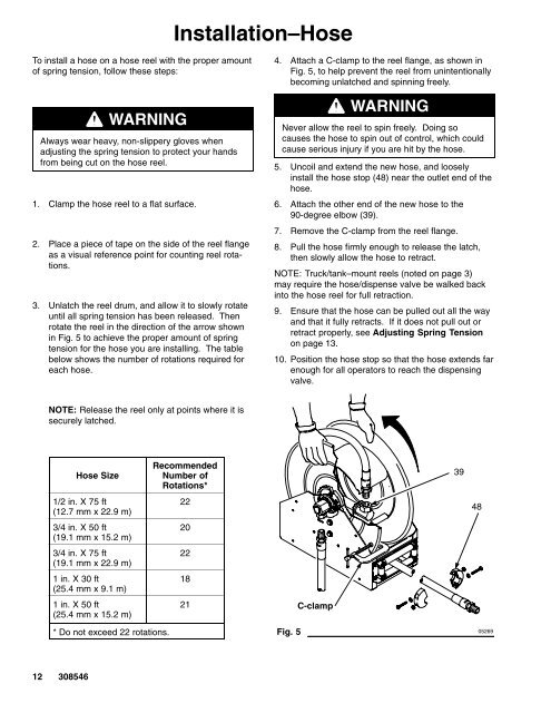
4. Attach a C-clamp to the reel flange, as shown in<br />
Fig. 5, to help prevent the reel from unintentionally<br />
becoming unlatched and spinning freely.<br />
WARNING<br />
Never allow the reel to spin freely. Doing so<br />
causes the hose to spin out of control, which could<br />
cause serious injury if you are hit by the hose.<br />
5. Uncoil and extend the new hose, and loosely<br />
install the hose stop (48) near the outlet end of the<br />
hose.<br />
6. Attach the other end of the new hose to the<br />
90-degree elbow (39).<br />
7. Remove the C-clamp from the reel flange.<br />
8. Pull the hose firmly enough to release the latch,<br />
then slowly allow the hose to retract.<br />
NOTE: Truck/tank–mount reels (noted on page 3)<br />
may require the hose/dispense valve be walked back<br />
into the hose reel for full retraction.<br />
9. Ensure that the hose can be pulled out all the way<br />
and that it fully retracts. If it does not pull out or<br />
retract properly, see Adjusting Spring Tension<br />
on page 13.<br />
10. Position the hose stop so that the hose extends far<br />
enough for all operators to reach the dispensing<br />
valve.<br />
NOTE: Release the reel only at points where it is<br />
securely latched.<br />
<strong>Hose</strong> Size<br />
1/2 in. X 75 ft<br />
(12.7 mm x 22.9 m)<br />
3/4 in. X 50 ft<br />
(19.1 mm x 15.2 m)<br />
3/4 in. X 75 ft<br />
(19.1 mm x 22.9 m)<br />
1 in. X 30 ft<br />
(25.4 mm x 9.1 m)<br />
1 in. X 50 ft<br />
(25.4 mm x 15.2 m)<br />
Recommended<br />
Number of<br />
Rotations*<br />
22<br />
20<br />
22<br />
18<br />
21<br />
C-clamp<br />
39<br />
48<br />
* Do not exceed 22 rotations.<br />
Fig. 5 05269<br />
12 308546


