

308546S Series 700 Hose Reels, Instructions-Parts ... - Graco Inc.
308546S Series 700 Hose Reels, Instructions-Parts ... - Graco Inc.
308546S Series 700 Hose Reels, Instructions-Parts ... - Graco Inc.

Create successful ePaper yourself
Turn your PDF publications into a flip-book with our unique Google optimized e-Paper software.
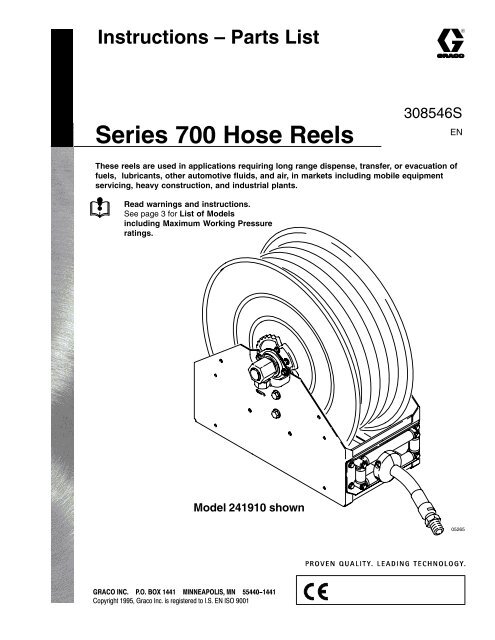
<strong>Instructions</strong> – <strong>Parts</strong> List<br />
<strong>Series</strong> <strong>700</strong> <strong>Hose</strong> <strong>Reels</strong><br />
<strong>308546S</strong><br />
EN<br />
These reels are used in applications requiring long range dispense, transfer, or evacuation of<br />
fuels, lubricants, other automotive fluids, and air, in markets including mobile equipment<br />
servicing, heavy construction, and industrial plants.<br />
Read warnings and instructions.<br />
See page 3 for List of Models<br />
including Maximum Working Pressure<br />
ratings.<br />
Model 241910 shown<br />
05265
Table of Contents<br />
List of Models . . . . . . . . . . . . . . . . . . . . . . . . . . . . . . 3<br />
Warnings . . . . . . . . . . . . . . . . . . . . . . . . . . . . . . . . . . . 4<br />
Installation<br />
Typical Layout . . . . . . . . . . . . . . . . . . . . . . . . . . . . . . . . . 7<br />
Accessories and Restrictions . . . . . . . . . . . . . . . . . . . . 8<br />
Air Line Accessories . . . . . . . . . . . . . . . . . . . . . . . . . 8<br />
Fluid Line Accessories . . . . . . . . . . . . . . . . . . . . . . . 8<br />
Required Installation Accessories . . . . . . . . . . . . . . 8<br />
Mounting Restrictions . . . . . . . . . . . . . . . . . . . . . . . . 8<br />
Roller Support Arm . . . . . . . . . . . . . . . . . . . . . . . . . . . . . 9<br />
Overhead Reel Installation . . . . . . . . . . . . . . . . . . . . 9<br />
Mounting Options . . . . . . . . . . . . . . . . . . . . . . . . . . . . . 10<br />
All Mountings . . . . . . . . . . . . . . . . . . . . . . . . . . . . . . 10<br />
Overhead Mounting to an I-Beam . . . . . . . . . . . . . 11<br />
Installing a <strong>Hose</strong> . . . . . . . . . . . . . . . . . . . . . . . . . . . . . . 12<br />
Adjusting Spring Tension . . . . . . . . . . . . . . . . . . . . . . . 13<br />
Maintenance<br />
Pressure Relief Procedure . . . . . . . . . . . . . . . . . . . . . . 14<br />
Replacing the Service <strong>Hose</strong> . . . . . . . . . . . . . . . . . . . . . 14<br />
Oiling the <strong>Hose</strong> Rollers . . . . . . . . . . . . . . . . . . . . . . . . . 15<br />
Service<br />
Swivel . . . . . . . . . . . . . . . . . . . . . . . . . . . . . . . . . . . . . . . 16<br />
Spring Canister . . . . . . . . . . . . . . . . . . . . . . . . . . . . . . . 17<br />
Reel Ratchet and Dog . . . . . . . . . . . . . . . . . . . . . . . . . 17<br />
<strong>Parts</strong> List . . . . . . . . . . . . . . . . . . . . . . . . . . . . . . . . . . 18<br />
<strong>Parts</strong> Drawing . . . . . . . . . . . . . . . . . . . . . . . . . . . . . 19<br />
Accessories<br />
Identification Labels . . . . . . . . . . . . . . . . . . . . . . . . . . . 20<br />
Reel Mounting Kit . . . . . . . . . . . . . . . . . . . . . . . . . . . . . 20<br />
Roller Support Kit . . . . . . . . . . . . . . . . . . . . . . . . . . . . . 20<br />
Technical Data . . . . . . . . . . . . . . . . . . . . . . . . . . . . 21<br />
Dimensions . . . . . . . . . . . . . . . . . . . . . . . . . . . . . . . 22<br />
<strong>Graco</strong> Standard Warranty . . . . . . . . . . . . . . . . 24<br />
<strong>Graco</strong> Information . . . . . . . . . . . . . . . . . . . . . . . . 24<br />
2 308546
List of Models<br />
Model<br />
237728, <strong>Series</strong> B,<br />
bare hose reel<br />
237875, <strong>Series</strong> A,<br />
oil dispensing<br />
237879*, <strong>Series</strong> A,<br />
oil dispensing<br />
237881, <strong>Series</strong> A,<br />
oil dispensing<br />
241910*, <strong>Series</strong> A,<br />
oil dispensing and<br />
evacuation<br />
241909, <strong>Series</strong> A,<br />
oil dispensing and<br />
evacuation<br />
237884*, <strong>Series</strong> A,<br />
fuel dispensing<br />
Recommended<br />
Mounting<br />
Position<br />
Overhead or truck/<br />
tank<br />
<strong>Hose</strong><br />
Stop Kit<br />
<strong>Hose</strong><br />
Part No.<br />
<strong>Hose</strong><br />
Length<br />
NA none none N/A N/A<br />
237871 237861 75 ft<br />
(22.9 m)<br />
Truck/tank 237873 237865 75 ft<br />
(22.9 m)<br />
Overhead or truck/<br />
tank<br />
237873 237866 50 ft<br />
(15.2 m)<br />
Truck/tank 237874 241908 50 ft<br />
(15.2 m)<br />
Overhead or truck/<br />
tank<br />
237874 241907 30 ft<br />
(9.1 m)<br />
Truck/tank 237874 249058 50 ft<br />
(15.2 m)<br />
<strong>Hose</strong><br />
Diameter<br />
Max<br />
Working<br />
Pressure<br />
1/2 in.<br />
(12.7 mm) 1500 psi<br />
10.2 MPa<br />
3/4 in. 102 bar<br />
(19.1 mm)<br />
3/4 in.<br />
(19.1 mm)<br />
1 in.<br />
(25.4 mm)<br />
1 in.<br />
(25.4 mm)<br />
1 in.<br />
(25.4 mm)<br />
212 psi<br />
1.5 MPa<br />
15 bar<br />
125 psi<br />
0.87 MPa<br />
8.7 bar<br />
* Truck/tank–mounted hose reels may require the hose/dispense valve be walked back into the hose reel for full<br />
retraction.<br />
308546<br />
3
Symbols<br />
Warning Symbol<br />
WARNING<br />
This symbol alerts you to the possibility of serious<br />
injury or death if you do not follow the instructions.<br />
Caution Symbol<br />
CAUTION<br />
This symbol alerts you to the possibility of damage to<br />
or destruction of equipment if you do not follow the<br />
instructions.<br />
WARNING<br />
FIRE, EXPLOSION, and INJECTION<br />
HAZARD<br />
This hose reel is designed to dispense<br />
lube products, air, water, transmission<br />
fluid, antifreeze, gasoline, and diesel<br />
fuel only. Any other use can cause<br />
unsafe operating conditions and result in<br />
component rupture, fire, or explosion,<br />
which could cause serious injury, including<br />
fluid injection.<br />
EQUIPMENT MISUSE HAZARD<br />
WARNING<br />
Equipment misuse can cause the equipment to rupture or malfunction and result in serious injury.<br />
INSTRUCTIONS<br />
<br />
<br />
<br />
<br />
<br />
<br />
<br />
<br />
<br />
<br />
<br />
<br />
This equipment is for professional use only.<br />
Read all instruction manuals, tags, and labels before operating the equipment.<br />
Use the equipment only for its intended purpose. If you are not sure, call your <strong>Graco</strong> distributor.<br />
Do not alter or modify this equipment. Use only genuine <strong>Graco</strong> parts and accessories. Modifying<br />
parts can cause a malfunction and result in serious bodily injury.<br />
Check equipment daily. Repair or replace worn or damaged parts immediately.<br />
Do not exceed the maximum working pressure of the lowest rated system component. Refer to<br />
the Technical Data on page 21 for the maximum working pressure of this equipment.<br />
Use fluids and solvents that are compatible with the equipment wetted parts. Refer to the Technical<br />
Data section of all equipment manuals. Read the fluid and solvent manufacturer’s warnings.<br />
Do not use hoses to pull equipment.<br />
Route hoses away from traffic areas, sharp edges, moving parts, and hot surfaces. Do not<br />
expose hoses to temperatures above 82C (180F) or below –40C (–40F).<br />
Do not lift pressurized equipment.<br />
Comply with all applicable local, state, and national fire, electrical, and safety regulations.<br />
If you are adding a service hose and dispensing valve to a bare hose reel, be sure you know the<br />
maximum working pressure of all the components.<br />
4 308546
WARNING<br />
SKIN INJECTION HAZARD<br />
Fluid from the dispensing valve, leaks, or ruptured components can inject fluid into your body and<br />
cause extremely serious injury, including the need for amputation. Fluid splashed in the eyes or on<br />
the skin can also cause serious injury.<br />
<br />
<br />
<br />
<br />
<br />
<br />
<br />
<br />
Fluid injected into the skin might look like just a cut, but it is a serious injury. Get immediate<br />
surgical treatment.<br />
Do not point the dispensing valve at anyone or at any part of the body.<br />
Do not put your hand or fingers over the dispensing valve nozzle.<br />
Do not stop or deflect leaks with your hand, body, glove or rag.<br />
Follow the Pressure Relief Procedure on page 14 if the dispensing valve clogs and before<br />
cleaning, checking, or servicing the equipment.<br />
Tighten all fluid connections before operating the equipment.<br />
Check the hoses, tubes, and couplings daily. Replace worn or damaged parts immediately. Do<br />
not repair medium-pressure couplings; you must replace the entire hose.<br />
Do not attempt to force lubricant into a fitting. If the lubricant is not flowing, stop dispensing<br />
immediately; the fitting may be clogged.<br />
TOXIC FLUID HAZARD<br />
Hazardous fluid or toxic fumes can cause serious injury or death if inhaled, swallowed, splashed in<br />
the eyes, or splashed on the skin.<br />
<br />
<br />
<br />
Know the specific hazards of the fluid you are using.<br />
Store hazardous fluid in an approved container. Dispose of hazardous fluid according to all<br />
local, state and national guidelines.<br />
Always wear protective eyewear, gloves, clothing, and a respirator as recommended by the fluid<br />
and solvent manufacturer.<br />
308546<br />
5
FIRE AND EXPLOSION HAZARD<br />
WARNING<br />
Improper grounding, poor ventilation, open flames, or sparks can cause a hazardous condition and<br />
result in a fire or explosion and serious injury.<br />
<br />
<br />
<br />
<br />
<br />
Be sure the entire fluid system is properly grounded. The hoses supplied with these hose reels<br />
are electrically conductive. The hose reel is grounded by connecting electrically conductive<br />
supply hoses to a properly grounded system. Refer to your pump instruction manual for complete<br />
details.<br />
If there is any static sparking or you feel an electric shock while using this equipment, stop<br />
dispensing immediately. Do not use the equipment until you identify and correct the problem.<br />
Provide fresh air ventilation to avoid the buildup of flammable fumes from solvents or the fluid<br />
being dispensed.<br />
Keep the dispensing area free of debris, including solvent, rags, and spilled gasoline.<br />
Do not smoke while dispensing flammable fluids.<br />
6 308546
Installation–Typical Layout<br />
The installation shown in Fig.1 is only a guide for selecting and installing a hose reel system. The components and<br />
accessories shown are the minimum requirements for all systems; however, it is not an actual system design.<br />
Contact your <strong>Graco</strong> distributor for assistance in designing a system to suit your needs.<br />
A<br />
K<br />
P<br />
K<br />
P<br />
F<br />
L<br />
B<br />
C D E<br />
G<br />
KEY<br />
A<br />
B<br />
C<br />
D<br />
E<br />
F<br />
G<br />
H<br />
J<br />
K<br />
L<br />
M<br />
N<br />
P<br />
Q<br />
Main air supply line<br />
Pump air supply line<br />
Air filter<br />
Air regulator<br />
Bleed-type master air valve (required)<br />
Pump<br />
Pump grounding wire (required)<br />
Thermal relief valve (required)<br />
Dump valve (required)<br />
Fluid shut-off valve<br />
Fluid line<br />
<strong>Hose</strong> reel<br />
Dispensing valve<br />
Mounting channel/base<br />
Flexible inlet hose<br />
Q<br />
K<br />
H J<br />
N<br />
NOTE: <strong>Parts</strong> are not proportional.<br />
M<br />
N<br />
M<br />
Fig. 1<br />
05266<br />
308546<br />
7
Installation–Accessories and Restrictions<br />
NOTE: The air and fluid accessories for your pump<br />
must be properly sized to that pump. Refer to your<br />
specific pump manual for selecting pump accessories.<br />
WARNING<br />
FIRE, INJECTION, and ELECTRIC<br />
SHOCK HAZARD<br />
Four accessories are required in your<br />
system: ground wire, bleed-type master<br />
air valve, thermal relief valve, and dump<br />
valve. These accessories help reduce<br />
the risk of serious injury, including fire,<br />
electric shock, and fluid injection or<br />
splashing in the eyes or on the skin.<br />
These accessories are shown in Fig. 1.<br />
The ground wire (G) must be connected to the<br />
pump grounding lug and to a true earth ground<br />
according to your local code.<br />
The bleed-type master air valve (E) relieves air<br />
trapped between itself and the pump after the air is<br />
shut off. Trapped air can cause the pump to cycle<br />
unexpectedly. Install the valve close to the pump.<br />
The dump valve (J) relieves fluid pressure in the<br />
displacement pump, hose, and gun. Triggering the<br />
gun to relieve pressure may not be sufficient.<br />
The thermal relief valve (H) relieves pressure in the<br />
fluid line caused by heat expansion.<br />
Air Line Accessories<br />
Install the following air line accessories in the order<br />
shown in Fig. 1, using adapters as necessary:<br />
<br />
<br />
<br />
Bleed-type master air valve (E)<br />
Install downstream from the air regulator and close<br />
enough to the pump for easy access.<br />
Air regulator (D)<br />
Controls pump speed and outlet pressure by adjusting<br />
the air pressure to the pump. Locate the regulator<br />
close to the pump but upstream from the<br />
bleed-type master air valve.<br />
Air filter (C)<br />
Removes harmful dirt and moisture from the compressed<br />
air supply.<br />
Fluid Line Accessories<br />
Install the following fluid line accessories in the order<br />
shown in Fig. 1, using adapters as necessary:<br />
<br />
<br />
<br />
<br />
<br />
Thermal relief valve (H)<br />
Install so that the outlet points down.<br />
Dump valve (J)<br />
Install so that the outlet points down, and the<br />
handle points up when the valve is open.<br />
Fluid shutoff valve (K)<br />
Shuts off fluid flow to the hose reel.<br />
Dispensing valve (N)<br />
Dispenses the fluid.<br />
Flexible inlet hose (Q)<br />
Fluid inlet must be from a flexible hose, not fluid<br />
piping.<br />
Required Installation Accessories<br />
Be sure you have these accessories before starting<br />
the installation.<br />
<br />
<br />
Reel mounting bases and mounting brackets (if not<br />
mounting on a truck)<br />
Dispensing valves<br />
Mounting Restrictions<br />
<br />
<br />
Base-mounted hose rollers are for truck-mounted<br />
hose reels. Accessory roller support arms are<br />
available for overhead mounted hose reels. See<br />
Roller Support Arm for instructions on installing<br />
the roller support arm.<br />
<strong>Hose</strong> reel enclosures do not fit on these reels.<br />
WARNING<br />
To reduce the risk of injury when mounting a<br />
hose reel overhead, always use a lift truck.<br />
Position the hose reel so the mounting brackets<br />
are facing up. Using the lift truck, raise the hose<br />
reel as close to the I-beam as possible. Fasten<br />
the hose reel to the I-beam, and be sure it is<br />
secure before lowering the lift truck.<br />
8 308546
Installation–Roller Support Arm<br />
<strong>Series</strong> <strong>700</strong> hose reels are shipped with the hose<br />
rollers bolted near the reel mounting base, which is the<br />
proper position for truck-mounted hose reels. To<br />
mount the reel overhead, use the accessory roller<br />
support arm kit (237944).<br />
To install the accessory roller support arm, follow these<br />
steps (see Fig 2):<br />
1. Clamp the hose reel to a flat surface.<br />
2. Unwrap the hose so that it extends 3 ft (0.9 m)<br />
beyond the roller plate (28) while keeping the reel<br />
latched.<br />
NOTE: Do not pull the hose out by rotating the<br />
reel. Spring tension must be at a minimum.<br />
WARNING<br />
Never allow the reel to spin freely. Doing so<br />
causes the hose to spin out of control, which could<br />
cause serious injury if you are hit by the hose.<br />
3. Remove the roller plate from the hose reel base<br />
(14), and install the roller support arms (49).<br />
4. Reattach the roller plate to the roller support arms,<br />
as shown in Fig. 2.<br />
5. Reroute the hose through the hose rollers, as<br />
shown in Fig. 2.<br />
6. Install the hose stop (48) and dispensing valve (not<br />
shown).<br />
7. Unlatch the reel, and allow the hose to retract.<br />
See Mounting Options, beginning on page 10, for<br />
additional installation procedures.<br />
Overhead Reel Installation<br />
To ensure retraction when the hose is at maximum<br />
extension, rotate ratchet (43) counter-clockwise one<br />
screw hole (60).<br />
48<br />
43<br />
28<br />
14<br />
Fig. 2<br />
49<br />
05267<br />
308546<br />
9
Installation–Mounting Options<br />
All Mountings<br />
NOTE: Always use large flat washers with the bolts<br />
you use to mount the hose reel pedestal to any<br />
surface.<br />
2. If you are installing permanent supply lines, drill<br />
1.5 in. (38 mm) diameter holes through the ceiling<br />
on the inlet side of the reels.<br />
WARNING<br />
Be sure the mounting surface is strong enough to<br />
support the reel, the weight of the lubricants, and<br />
the stress caused by hard pulls on the service<br />
hoses. See page 21 for the dry weights of the<br />
various hose reel assemblies.<br />
1<br />
2<br />
3<br />
5 ft (1.5 m)<br />
for motor oil<br />
6 ft (1.9 m) minimum<br />
for 1 lift<br />
Center between<br />
two lifts<br />
NOTE: All accessories mentioned are shown on<br />
page 20.<br />
1<br />
1. Select the reel mounting location.<br />
a. For high ceilings, suspend a suitable support<br />
structure for the reels, so the hoses will be<br />
long enough to reach your service area.<br />
b. A reel mounted in a one-lift service bay should<br />
be at least 6 ft (1.9 m) from the center line of<br />
the lift. See Fig. 3.<br />
2<br />
3<br />
c. In a two-lift bay, mount the reel between the<br />
lifts and an equal distance from each lift. Oil<br />
reels should be mounted about 5 ft (1.5 m)<br />
from the center of the lift, toward the front of<br />
the lift rails. See Fig. 3.<br />
Fig. 3<br />
1639<br />
10 308546
Installation–Mounting Options<br />
Overhead Mounting to an I-Beam<br />
NOTE: You should have the hose installed on the reel<br />
before you mount the reel overhead. See Installing a<br />
<strong>Hose</strong> on page 12 if you do not already have the hose<br />
installed on the reel.<br />
1. Line up the four holes on the hose reel mounting<br />
base with the holes near the ends of the mounting<br />
brackets (A) (see Fig. 4), and securely bolt the<br />
hose reel to the mounting brackets.<br />
3. Connect the supply line to the inlet of the reel.<br />
4. Adjust the spring tension of the reel. See Adjusting<br />
Spring Tension on page 13.<br />
2. Position and securely tighten the adjustable<br />
clamps (C) of the mounting brackets on the<br />
flanges of the I-beam (B).<br />
WARNING<br />
C<br />
B<br />
To reduce the risk of injury when mounting a<br />
hose reel overhead, always use a lift truck.<br />
Position the hose reel so the mounting brackets<br />
are facing up. Using the lift truck, raise the hose<br />
reel as close to the I-beam as possible. Fasten<br />
the hose reel to the I-beam, and be sure it is<br />
secure before lowering the lift truck.<br />
Fig. 4<br />
A<br />
05268<br />
308546<br />
11
Installation–<strong>Hose</strong><br />
To install a hose on a hose reel with the proper amount<br />
of spring tension, follow these steps:<br />
WARNING<br />
Always wear heavy, non-slippery gloves when<br />
adjusting the spring tension to protect your hands<br />
from being cut on the hose reel.<br />
1. Clamp the hose reel to a flat surface.<br />
2. Place a piece of tape on the side of the reel flange<br />
as a visual reference point for counting reel rotations.<br />
3. Unlatch the reel drum, and allow it to slowly rotate<br />
until all spring tension has been released. Then<br />
rotate the reel in the direction of the arrow shown<br />
in Fig. 5 to achieve the proper amount of spring<br />
tension for the hose you are installing. The table<br />
below shows the number of rotations required for<br />
each hose.<br />
4. Attach a C-clamp to the reel flange, as shown in<br />
Fig. 5, to help prevent the reel from unintentionally<br />
becoming unlatched and spinning freely.<br />
WARNING<br />
Never allow the reel to spin freely. Doing so<br />
causes the hose to spin out of control, which could<br />
cause serious injury if you are hit by the hose.<br />
5. Uncoil and extend the new hose, and loosely<br />
install the hose stop (48) near the outlet end of the<br />
hose.<br />
6. Attach the other end of the new hose to the<br />
90-degree elbow (39).<br />
7. Remove the C-clamp from the reel flange.<br />
8. Pull the hose firmly enough to release the latch,<br />
then slowly allow the hose to retract.<br />
NOTE: Truck/tank–mount reels (noted on page 3)<br />
may require the hose/dispense valve be walked back<br />
into the hose reel for full retraction.<br />
9. Ensure that the hose can be pulled out all the way<br />
and that it fully retracts. If it does not pull out or<br />
retract properly, see Adjusting Spring Tension<br />
on page 13.<br />
10. Position the hose stop so that the hose extends far<br />
enough for all operators to reach the dispensing<br />
valve.<br />
NOTE: Release the reel only at points where it is<br />
securely latched.<br />
<strong>Hose</strong> Size<br />
1/2 in. X 75 ft<br />
(12.7 mm x 22.9 m)<br />
3/4 in. X 50 ft<br />
(19.1 mm x 15.2 m)<br />
3/4 in. X 75 ft<br />
(19.1 mm x 22.9 m)<br />
1 in. X 30 ft<br />
(25.4 mm x 9.1 m)<br />
1 in. X 50 ft<br />
(25.4 mm x 15.2 m)<br />
Recommended<br />
Number of<br />
Rotations*<br />
22<br />
20<br />
22<br />
18<br />
21<br />
C-clamp<br />
39<br />
48<br />
* Do not exceed 22 rotations.<br />
Fig. 5 05269<br />
12 308546
Installation–Adjusting Spring Tension<br />
If the hose cannot be pulled out all the way, or if it does<br />
not retract all the way back onto the hose reel, you<br />
need to adjust the spring tension. To do so, follow<br />
these steps:<br />
WARNING<br />
Always wear heavy, non-slippery gloves when<br />
adjusting the spring tension to protect your hands<br />
from being cut on the hose reel.<br />
5. Check the spring tension. The hose must pull out<br />
fully and retract fully.<br />
NOTE: Truck/tank–mount reels (noted on page 3)<br />
may require the hose/dispense valve be walked back<br />
into the hose reel for full retraction.<br />
6. Repeat Steps 4 and 5 until you have the proper<br />
amount of spring tension.<br />
1. Pull the hose out and engage the latch.<br />
2. Remove the dispensing valve (not shown) and the<br />
hose stop (48). See Fig. 6.<br />
3. Pull the loose end of the hose back in through the<br />
hose rollers, and manually wrap the hose onto the<br />
reel.<br />
4. Rotate the reel in the direction of the appropriate<br />
arrow shown in Fig. 6, keeping the hose wrapped<br />
on the reel. Each rotation of the reel increases or<br />
decreases enough spring tension to retract or let<br />
out approximately 5 ft (1.5 m) of hose.<br />
CAUTION<br />
Do not increase the spring tension so much that the<br />
spring winds up tightly before the hose is fully<br />
extended. A spring that is wound too tightly stops<br />
the reel from rotating before the hose is fully extended,<br />
which puts excessive strain on the hose and<br />
reel spring and could damage the reel.<br />
7. Reroute the hose through the hose rollers, and<br />
reinstall the hose stop and dispensing valve.<br />
decrease<br />
tension<br />
increase<br />
tension<br />
1 Position hose stop (48) within operator’s reach.<br />
1<br />
Fig. 6<br />
48<br />
05270<br />
308546<br />
13
Maintenance<br />
Pressure Relief Procedure<br />
WARNING<br />
INJECTION HAZARD<br />
The system pressure must be manually<br />
relieved to prevent the system from dispensing<br />
accidentally. Fluid under high<br />
pressure can be injected through the skin and<br />
cause serious injury. To reduce the risk of an injury<br />
from injection, splashing fluid, or moving parts, follow<br />
the Pressure Relief Procedure whenever you<br />
Are instructed to relieve the pressure<br />
Stop dispensing<br />
Check or service any of the system equipment<br />
Install or clean the dispensing valve<br />
Replacing the Service <strong>Hose</strong><br />
WARNING<br />
To reduce the risk of serious injury whenever you<br />
are instructed to relieve pressure, always follow the<br />
Pressure Relief Procedure at left.<br />
1. Relieve the pressure if you are replacing the<br />
service hose on a reel that is already truck<br />
mounted or overhead mounted. Then go to<br />
Step 3. Otherwise, start at Step 2.<br />
2. Clamp the hose reel to a flat surface if you are<br />
replacing the service hose on a reel that is not<br />
mounted anywhere.<br />
3. Fully extend the hose and latch the reel.<br />
1. Close the supply pump’s bleed-type master air<br />
valve (required in pneumatic systems).<br />
2. Open the dispensing valve until pressure is fully<br />
relieved.<br />
3. Open the dump valve at the pump fluid outlet, and<br />
leave it open until you are ready to use the system<br />
again.<br />
If you suspect that the dispensing valve or extension is<br />
clogged or that pressure has not been fully relieved<br />
after following all the steps above, very slowly loosen<br />
the coupler or hose end coupling, and allow pressure<br />
to be relieved gradually, then loosen the part completely.<br />
Then clear the clog.<br />
4. Attach a C-clamp to the reel flange to help prevent<br />
the reel from unintentionally becoming unlatched<br />
and spinning freely. See Fig. 7.<br />
WARNING<br />
Never allow the reel to spin freely. Doing so<br />
causes the hose to spin out of control, which could<br />
cause serious injury if you are hit by the hose.<br />
5. Disconnect the service hose from the 90-degree<br />
elbow (39), and remove it.<br />
6. Uncoil and extend the new hose, and install the<br />
hose stop (48) near the outlet end of the hose.<br />
14 308546
Maintenance<br />
7. Attach the other end of the new hose to the<br />
90-degree elbow.<br />
8. Remove the C-clamp from the reel flange.<br />
9. Pull the hose firmly enough to release the latch,<br />
then slowly allow the hose to retract.<br />
10. Position the hose stop so the hose extends far<br />
enough for all operators to reach the dispensing<br />
valve.<br />
Oiling the <strong>Hose</strong> Rollers<br />
Every six months, apply one or two drops of light<br />
motor oil to lubricate the hose reel at point A. See<br />
Fig. 8.<br />
A<br />
39<br />
48<br />
A<br />
Fig. 8<br />
05272<br />
C-clamp<br />
Fig. 7<br />
05271<br />
308546<br />
15
Service<br />
Swivel<br />
WARNING<br />
To reduce the risk of serious injury whenever you<br />
are instructed to relieve pressure, always follow the<br />
Pressure Relief Procedure on page 14.<br />
1. Relieve the pressure.<br />
2. Remove the retaining ring (35) and the swivel<br />
connector (34) (see Fig. 9).<br />
3. Remove the o-rings (36), backup rings (37), and<br />
quad rings (38), and clean and inspect them for<br />
wear or damage.<br />
4. Lubricate the new rings, shaft, and bearing surfaces<br />
with high-quality grease.<br />
5. Install the parts as shown in Fig. 9.<br />
sixth<br />
fourth<br />
second<br />
first<br />
38<br />
37<br />
36<br />
36<br />
37<br />
Packing Detail<br />
Install 36, 37, and 38 in the<br />
order shown at left.<br />
36<br />
37<br />
35<br />
34<br />
third<br />
fifth<br />
38<br />
05274 05273<br />
Fig. 9<br />
16 308546
Spring Canister<br />
To replace the spring canister, follow the steps below.<br />
Do not attempt to service the spring inside of the<br />
spring canister. Read the warning below regarding the<br />
spring hazard.<br />
Service<br />
2<br />
10<br />
8<br />
WARNING<br />
6<br />
HOSE REEL SPRING HAZARD<br />
The only service you should perform on<br />
the reel spring is replacing the spring<br />
cannister. The spring is under extreme<br />
tension and could be propelled out of the opened<br />
canister and cause serious injury.<br />
Fig. 10<br />
4<br />
05275B<br />
7<br />
1. Ensure that the hose is fully retracted, to minimize<br />
spring tension.<br />
2. Remove the four bolts (7) that hold the spring<br />
canister to the hose reel base. See Fig. 10.<br />
3. Remove the old spring canister (8), and discard<br />
the whole unit.<br />
Reel Ratchet and Dog<br />
If the ratchet and dog malfunction or become sluggish,<br />
disassemble the mechanism. See Fig. 11. Clean and<br />
lubricate or replace the broken or worn components as<br />
necessary. See the <strong>Parts</strong> List on page 18 for part<br />
numbers and names.<br />
4. Adhere new dust seal (4) to flat side of spring<br />
canister (8), concentric with center hole.<br />
5. Install the new spring canister over the shaft (2)<br />
and hub (10). To make this installation easier,<br />
remove the plastic end cap (6).<br />
43<br />
19<br />
18<br />
16<br />
15<br />
6. Bolt the new spring canister to the base, and<br />
replace the plastic end cap.<br />
7. Rotate the reel in the direction of the arrow shown<br />
in Fig.10 to achieve the proper amount of spring<br />
tension (see Adjusting Spring Tension on page<br />
13 for the approximate number of rotations).<br />
29<br />
WARNING<br />
32<br />
Never allow the reel to spin freely. Doing so<br />
causes the hose to spin out of control, which could<br />
cause serious injury if you are hit by the hose.<br />
Fig. 11<br />
30<br />
05276B<br />
308546<br />
17
<strong>Parts</strong> List<br />
Model 237728, <strong>Series</strong> B<br />
Bare <strong>Hose</strong> Reel<br />
Ref<br />
No. Part No. Description Qty<br />
1 190725 SPOOL, hose 1<br />
2 190373 SHAFT, spring cannister 1<br />
3 113267 KEY, square 1<br />
4 113051 SEAL, dust 1<br />
5 290070 LABEL, warning 1<br />
6 112961 CAP, end 1<br />
7 110963 SCREW, cap, 5/16–18 x 3/4 in. 14<br />
8 238112 Kit, spring replacement 1<br />
9 106082 RING, retaining, external 3<br />
10 178681 HUB, reel 1<br />
11 177679 WASHER, retaining 5<br />
12 112954 FLANGE, bearing 4<br />
13 112953 BEARING, ball 2<br />
14 190726 BASE, hose reel 1<br />
15 101079 RING, retaining 1<br />
16 276382 RATCHET DOG 1<br />
18 110974 BEARING 1<br />
19 186583 SPRING, torsion 1<br />
20 110996 NUT, flange head, 5/16–18 8<br />
21 167030 PIN, roller 2<br />
22 190376 CAP, roller 8<br />
23 190378 TUBE, roller, 1.48 in. 2<br />
24 190361 POST, corner 4<br />
25 112960 SCREW, cap, flange head,<br />
5/16–18 x 1.75 in. 4<br />
Ref<br />
No. Part No. Description Qty<br />
26 190377 TUBE, roller, 7.05 in. 2<br />
27 190363 PIN, roller 2<br />
28 190729 PLATE, roller 1<br />
29 102005 PIN, spring 1<br />
30 223962 BRACKET, latch 1<br />
31 290019 LABEL, logo 2<br />
(one on each side of base)<br />
32 111802 SCREW, flange head,<br />
1/2–13 x 0.75 in. 2<br />
33 112958 NUT, hex, flanged 2<br />
34 112951 CONNECTOR, swivel 1<br />
35 112938 RING, retaining, external 1<br />
36* 166080 PACKING, o-ring 2<br />
37* 112956 PACKING, backup ring 2<br />
38* 112952 RING, quad ring 2<br />
39 112955 ELBOW, female, 90-degree 1<br />
40 104859 SCREW, pan head, #10 x .375 2<br />
41 190364 BRACKET 1<br />
42 237654 SHAFT, reel, 1<br />
43 276367 RATCHET 1<br />
44 112586 SCREW, flange head,<br />
5/16–18 x 1 in. 6<br />
45 190367 TEMPLATE, mounting 1<br />
(not shown)<br />
46 113994 WASHER, wave 1<br />
* These parts are also included in repair kit 237901, which may be purchased separately. Keep a repair kit on<br />
hand to reduce down time.<br />
<br />
Extra warning labels are available for free.<br />
These parts are also included in Spring Replacement Kit 238112.<br />
18 308546
<strong>Parts</strong> Drawing<br />
Model 237728, <strong>Series</strong> B<br />
Bare <strong>Hose</strong> Reel<br />
1 Apply lubricant to all bearing and sealing surfaces.<br />
2<br />
Use washers for .030-in. (0.76 mm) maximum space between back of bearing<br />
and retaining washer.<br />
3 Torque to 25 to 35 ft-lb (33.9 to 47.5 N.m).<br />
4 Bearings must be positioned with the 1/4-in. center extension facing the reel.<br />
1 2 3<br />
4<br />
5<br />
6<br />
7<br />
3<br />
7<br />
3<br />
8<br />
11<br />
9<br />
44<br />
36<br />
3<br />
43<br />
37<br />
42<br />
1<br />
41 40<br />
12<br />
39<br />
13 4<br />
12<br />
12<br />
13 4<br />
14<br />
12<br />
15<br />
16<br />
11<br />
2<br />
10<br />
9<br />
38<br />
18<br />
19<br />
20<br />
21<br />
22<br />
23<br />
7 3<br />
35<br />
34<br />
9<br />
46<br />
33<br />
3<br />
32<br />
3<br />
31<br />
30<br />
29<br />
28<br />
27<br />
26<br />
22<br />
22<br />
24<br />
25<br />
3<br />
22<br />
05277<br />
308546<br />
19
Accessories<br />
Must be purchased separately. Use only<br />
genuine <strong>Graco</strong> parts and accessories.<br />
Identification Labels 180698<br />
Sheet of 14 sticky-back labels for labeling hose reels.<br />
<strong>Inc</strong>ludes labels for the following:<br />
SAE 10–40 SAE 20W HYDRAULIC AIR<br />
SAE 10–30 SAE 30W ANTI–FREEZE ATF<br />
SAE 5–40 DEXRON CHASSIS<br />
SAE 10W WATER GEAR<br />
Roller Support Kit 237944<br />
Positions the roller plate for overhead installations and<br />
enables the hose to hang straight down through the<br />
hose rollers.<br />
Roller support arms<br />
Reel Mounting Kit 237932<br />
Secures mounting base to I-beam without the need for<br />
drilling holes in the I-beam. Two brackets hold one<br />
<strong>Series</strong> <strong>700</strong> hose reel. The mounting brackets fit all<br />
standard I-beams with flanges up to 7 in. (178 mm).<br />
Mount the brackets to the hose reel before securing<br />
them to the I-beam.<br />
Adjustable clamp<br />
I-beam<br />
05438<br />
Roller plate and<br />
hose rollers<br />
(included with<br />
hose reel)<br />
Mounting bracket<br />
05268<br />
20 308546
Technical Data<br />
Maximum working pressure<br />
Models 237728, 237875, 237879, 237881 . . . . . . . . . . . . . . . . . . . . . . . . . . . . . . . . . . . . 1500 psi (10 MPa, 102 bar)<br />
Models 241909, 241910 . . . . . . . . . . . . . . . . . . . . . . . . . . . . . . . . . . . . . . . . . . . . . . . . . . . . . . 212 psi (1.5 MPa, 15 bar)<br />
Model 237884 . . . . . . . . . . . . . . . . . . . . . . . . . . . . . . . . . . . . . . . . . . . . . . . . . . . . . . . . . . . . . 125 psi (0.87 MPa, 8.7 bar)<br />
Inlet size . . . . . . . . . . . . . . . . . . . . . . . . . . . . . . . . . . . . . . . . . . . . . . . . . . . . . . . . . . . . . . . . . . . . . . . . . . . . . . . . . . . . . . 1 npt(f)<br />
Outlet size . . . . . . . . . . . . . . . . . . . . . . . . . . . . . . . . . . . . . . . . . . . . . . . . . . . . . . . . . . . . . . . . . . . . . . . . . . . . . . . . . . . 1 npsm(f)<br />
* Maximum sound pressure . . . . . . . . . . . . . . . . . . . . . . . . . . . . . . . . . . . . . . . . . . . . . . . . . . . . . . . . . . . . . . . . . . . . 81 dB(A)<br />
Operating temperature . . . . . . . . . . . . . . . . . . . . . . . . . . . . . . . . . . . . . . . . . . . . . . . . –40 F to 160 F (–40 C to 82 C)<br />
Bearings . . . . . . . . . . . . . . . . . . . . . . . . . . . . . . . . . . . . . . . . . . . . . . . . . . . . . . . . . . . . . . . . . . . . . . . . . . . . . . . . . carbon steel<br />
Wetted parts . . . . . . . . . . . . . . . . . . . . . . . . . . . . . . . . . . . . . . . . . . . . . . . . . . . . . . . . . . . . . . . . carbon steel, fluoroelastomer<br />
Dry weights<br />
Model 237728 . . . . . . . . . . . . . . . . . . . . . . . . . . . . . . . . . . . . . . . . . . . . . . . . . . . . . . . . . . . . . . . . . . . . . . . 103 lb (46.8 kg)<br />
Model 237875 . . . . . . . . . . . . . . . . . . . . . . . . . . . . . . . . . . . . . . . . . . . . . . . . . . . . . . . . . . . . . . . . . . . . . . . 124 lb (56.3 kg)<br />
Model 237879 . . . . . . . . . . . . . . . . . . . . . . . . . . . . . . . . . . . . . . . . . . . . . . . . . . . . . . . . . . . . . . . . . . . . . . . 143 lb (64.9 kg)<br />
Model 237881 . . . . . . . . . . . . . . . . . . . . . . . . . . . . . . . . . . . . . . . . . . . . . . . . . . . . . . . . . . . . . . . . . . . . . . . 130 lb (59.0 kg)<br />
Model 241910 . . . . . . . . . . . . . . . . . . . . . . . . . . . . . . . . . . . . . . . . . . . . . . . . . . . . . . . . . . . . . . . . . . . . . . . 139 lb (63.1 kg)<br />
Model 241909 . . . . . . . . . . . . . . . . . . . . . . . . . . . . . . . . . . . . . . . . . . . . . . . . . . . . . . . . . . . . . . . . . . . . . . . 125 lb (56.8 kg)<br />
Model 237884 . . . . . . . . . . . . . . . . . . . . . . . . . . . . . . . . . . . . . . . . . . . . . . . . . . . . . . . . . . . . . . . . . . . . . . . 134 lb (60.8 kg)<br />
* Sound pressure was measured per ISO 3744 at assumed maximum retraction rate at assumed operator<br />
position.<br />
308546<br />
21
Dimensions<br />
F<br />
G<br />
E<br />
D<br />
B<br />
J<br />
A<br />
C<br />
H<br />
A<br />
B<br />
C<br />
D<br />
E<br />
F<br />
G<br />
H<br />
J<br />
10.45 in. (265 mm) mounting holes, center to center<br />
22.25 in. (565 mm) mounting holes, center to center<br />
11.83 in. (300 mm) base width<br />
24.00 in. (609 mm) base length<br />
26.25 in. (667 mm) total height<br />
25.00 in. (635 mm) reel diameter<br />
13.60 in. (345 mm) swivel height<br />
15.80 in. (401 mm) total width, swivel to spring canister<br />
2.20 in. (56 mm) swivel to base<br />
05278<br />
Mounting Hole Pattern for 1-in. (25.4 mm)<br />
Clearance Between <strong>Hose</strong> <strong>Reels</strong><br />
Reel #1 Reel #2 22.25 in<br />
(565 mm<br />
10.45 in.<br />
(265 mm)<br />
6.35 in.<br />
(161 mm)<br />
10.45 in.<br />
(265 mm)<br />
22 308546
Notes<br />
308546<br />
23
<strong>Graco</strong> Standard Warranty<br />
<strong>Graco</strong> warrants all equipment manufactured by <strong>Graco</strong> and bearing its name to be free from defects in material and workmanship on the<br />
date of sale to the original purchaser for use. With the exception of any special, extended, or limited warranty published by <strong>Graco</strong>,<br />
<strong>Graco</strong> will, for a period of twelve months from the date of sale, repair or replace any part of the equipment determined by <strong>Graco</strong> to be<br />
defective. This warranty applies only when the equipment is installed, operated and maintained in accordance with <strong>Graco</strong>’s written<br />
recommendations.<br />
This warranty does not cover, and <strong>Graco</strong> shall not be liable for general wear and tear, or any malfunction, damage or wear caused by<br />
faulty installation, misapplication, abrasion, corrosion, inadequate or improper maintenance, negligence, accident, tampering, or substitution<br />
of non-<strong>Graco</strong> component parts. Nor shall <strong>Graco</strong> be liable for malfunction, damage or wear caused by the incompatibility of<br />
<strong>Graco</strong> equipment with structures, accessories, equipment or materials not supplied by <strong>Graco</strong>, or the improper design, manufacture,<br />
installation, operation or maintenance of structures, accessories, equipment or materials not supplied by <strong>Graco</strong>.<br />
This warranty is conditioned upon the prepaid return of the equipment claimed to be defective to an authorized <strong>Graco</strong> distributor for<br />
verification of the claimed defect. If the claimed defect is verified, <strong>Graco</strong> will repair or replace free of charge any defective parts. The<br />
equipment will be returned to the original purchaser transportation prepaid. If inspection of the equipment does not disclose any defect<br />
in material or workmanship, repairs will be made at a reasonable charge, which charges may include the costs of parts, labor, and<br />
transportation.<br />
THIS WARRANTY IS EXCLUSIVE, AND IS IN LIEU OF ANY OTHER WARRANTIES, EXPRESS OR IMPLIED, INCLUDING BUT<br />
NOT LIMITED TO WARRANTY OF MERCHANTABILITY OR WARRANTY OF FITNESS FOR A PARTICULAR PURPOSE.<br />
<strong>Graco</strong>’s sole obligation and buyer’s sole remedy for any breach of warranty shall be as set forth above. The buyer agrees that no other<br />
remedy (including, but not limited to, incidental or consequential damages for lost profits, lost sales, injury to person or property, or any<br />
other incidental or consequential loss) shall be available. Any action for breach of warranty must be brought within two (2) years of the<br />
date of sale.<br />
<strong>Graco</strong> makes no warranty, and disclaims all implied warranties of merchantability and fitness for a particular purpose in connection<br />
with accessories, equipment, materials or components sold but not manufactured by <strong>Graco</strong>. These items sold, but not manufactured<br />
by <strong>Graco</strong> (such as electric motors, switches, hose, etc.), are subject to the warranty, if any, of their manufacturer. <strong>Graco</strong> will provide<br />
purchaser with reasonable assistance in making any claim for breach of these warranties.<br />
In no event will <strong>Graco</strong> be liable for indirect, incidental, special or consequential damages resulting from <strong>Graco</strong> supplying equipment<br />
hereunder, or the furnishing, performance, or use of any products or other goods sold hereto, whether due to a breach of contract,<br />
breach of warranty, the negligence of <strong>Graco</strong>, or otherwise.<br />
FOR GRACO CANADA CUSTOMERS<br />
The parties acknowledge that they have required that the present document, as well as all documents, notices and legal proceedings<br />
entered into, given or instituted pursuant hereto or relating directly or indirectly hereto, be drawn up in English. Les parties reconnaissent<br />
avoir convenu que la rédaction du présente document sera en Anglais, ainsi que tous documents, avis et procédures judiciaires<br />
exécutés, donnés ou intentés à la suite de ou en rapport, directement ou indirectement, avec les procedures concernées.<br />
<strong>Graco</strong> Information<br />
TO PLACE AN ORDER, contact your <strong>Graco</strong> distributor, or call one of the following numbers<br />
to identify the distributor closest to you:<br />
1–800–533–9655 Toll Free<br />
612–623–6928<br />
612–378–3590 Fax<br />
All written and visual data contained in this document reflects the latest product information available at the time of publication.<br />
<strong>Graco</strong> reserves the right to make changes at any time without notice.<br />
This manual contains English. MM 308546<br />
<strong>Graco</strong> Headquarters: Minneapolis<br />
International Offices: Belgium, Korea, China, Japan<br />
24 308546<br />
www.graco.com<br />
08/1995, Revised March 2012


