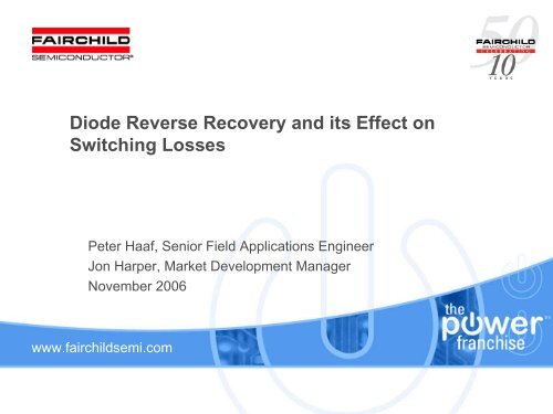
Diode Reverse Recovery and its Effect on Switching Losses
Diode Reverse Recovery and its Effect on Switching Losses
Diode Reverse Recovery and its Effect on Switching Losses

You also want an ePaper? Increase the reach of your titles
YUMPU automatically turns print PDFs into web optimized ePapers that Google loves.
<str<strong>on</strong>g>Diode</str<strong>on</strong>g> <str<strong>on</strong>g>Reverse</str<strong>on</strong>g> <str<strong>on</strong>g>Recovery</str<strong>on</strong>g> <str<strong>on</strong>g>and</str<strong>on</strong>g> <str<strong>on</strong>g>its</str<strong>on</strong>g> <str<strong>on</strong>g>Effect</str<strong>on</strong>g> <strong>on</strong><br />
<strong>Switching</strong> <strong>Losses</strong><br />
Peter Haaf, Senior Field Applicati<strong>on</strong>s Engineer<br />
J<strong>on</strong> Harper, Market Development Manager<br />
November 2006<br />
www.fairchildsemi.com
Agenda<br />
1. Basics<br />
2. Mathematical Estimati<strong>on</strong>s<br />
3. Comparis<strong>on</strong> of the Estimati<strong>on</strong>s with real measurements<br />
4. <strong>Switching</strong> <strong>Losses</strong> vs. Voltage<br />
5. <strong>Switching</strong> <strong>Losses</strong> vs. Current<br />
6. E ON <strong>Losses</strong> during Hard <strong>Switching</strong> with different <str<strong>on</strong>g>Diode</str<strong>on</strong>g><br />
Technologies<br />
7. <str<strong>on</strong>g>Effect</str<strong>on</strong>g> of parallel Caps <strong>on</strong> <strong>Switching</strong> <strong>Losses</strong><br />
8. <strong>Switching</strong> <strong>Losses</strong> vs. rise <str<strong>on</strong>g>and</str<strong>on</strong>g> fall time<br />
9. Summary<br />
2
<str<strong>on</strong>g>Diode</str<strong>on</strong>g> charge distributi<strong>on</strong> in c<strong>on</strong>ducting<br />
<str<strong>on</strong>g>and</str<strong>on</strong>g> n<strong>on</strong>-c<strong>on</strong>ducting states<br />
Minority carrier c<strong>on</strong>centrati<strong>on</strong><br />
near the juncti<strong>on</strong><br />
Minority carrier c<strong>on</strong>centrati<strong>on</strong><br />
near the juncti<strong>on</strong><br />
Electr<strong>on</strong><br />
c<strong>on</strong>centrati<strong>on</strong><br />
in P-type regi<strong>on</strong><br />
Hole<br />
c<strong>on</strong>centrati<strong>on</strong><br />
in N-type regi<strong>on</strong><br />
Electr<strong>on</strong><br />
c<strong>on</strong>centrati<strong>on</strong><br />
in P-type regi<strong>on</strong><br />
Hole<br />
c<strong>on</strong>centrati<strong>on</strong><br />
in N-type regi<strong>on</strong><br />
x=0<br />
x<br />
x=0<br />
x<br />
P-type<br />
N-type<br />
P-type<br />
N-type<br />
<str<strong>on</strong>g>Diode</str<strong>on</strong>g> c<strong>on</strong>ducting<br />
<str<strong>on</strong>g>Diode</str<strong>on</strong>g> blocking<br />
3
<str<strong>on</strong>g>Diode</str<strong>on</strong>g> Forced Commutati<strong>on</strong> Behavior<br />
V DD<br />
DC Bus<br />
I L<br />
Switch<br />
I DIODE<br />
-<br />
2<br />
1<br />
+<br />
+<br />
3<br />
-<br />
V DIODE<br />
V SWITCH<br />
Step 1: Switch is turned <strong>on</strong><br />
Current rises<br />
Step 2:<br />
Switch is turned off<br />
Current is circulating<br />
Step 3: Switch is turned <strong>on</strong><br />
again, <str<strong>on</strong>g>Diode</str<strong>on</strong>g> is<br />
recovering <str<strong>on</strong>g>and</str<strong>on</strong>g><br />
current c<strong>on</strong>tinues<br />
rising<br />
Reference GND<br />
I SWITCH<br />
4
<strong>Switching</strong> loss calculati<strong>on</strong>s<br />
• Definiti<strong>on</strong> of<br />
Power <strong>Losses</strong><br />
P = 1/T* ∫ V(t) * I(t) dt<br />
= mean (V(t) * I(t))<br />
I<br />
V<br />
E = P * t<br />
= ∫ V(t) * I(t) dt<br />
= area (V(t) * I(t))<br />
t<br />
P<strong>on</strong> = E ON<br />
* f ;<br />
Poff = E OFF<br />
* f<br />
E=(1/2)*V*I*t E=(1/3)*V*I*t E=(1/6)*V*I*t<br />
t t t<br />
5
Turn On Loss Due to <str<strong>on</strong>g>Diode</str<strong>on</strong>g> <str<strong>on</strong>g>Recovery</str<strong>on</strong>g> (Phase t R )<br />
V CE<br />
t = t 0<br />
IGBT turns <strong>on</strong><br />
o<br />
dI C /dt<br />
dI F /dt<br />
t 0<br />
I C<br />
t A<br />
t B<br />
t F<br />
I RRM<br />
V F<br />
I F<br />
V RM<br />
I RRM<br />
t R<br />
t 1 t 2 t 3<br />
I L assumed c<strong>on</strong>stant during switching time<br />
with<br />
V out I L t<br />
E <strong>on</strong>1<br />
= * *<br />
2<br />
dI/dt = I L / t R<br />
2<br />
Vout<br />
I L<br />
E <strong>on</strong>1<br />
= *<br />
2 * dI/dt<br />
switching time: t R<br />
+t A<br />
+t B<br />
R<br />
6
Turn On Loss Due to <str<strong>on</strong>g>Diode</str<strong>on</strong>g> <str<strong>on</strong>g>Recovery</str<strong>on</strong>g> (Phase t A )<br />
V CE<br />
t = t 0<br />
IGBT turns <strong>on</strong><br />
dI C /dt<br />
dI F /dt<br />
t 0<br />
I C<br />
I RRM<br />
t A t B<br />
t F<br />
V F<br />
I F<br />
V RM<br />
I RRM<br />
t R<br />
t 1 t 2 t 3<br />
I L assumed c<strong>on</strong>stant during switching time<br />
=<br />
RRM<br />
E <strong>on</strong>2 Vout<br />
* I L + *<br />
with<br />
E =<br />
<strong>on</strong>2<br />
V out*<br />
*<br />
⎝<br />
switching time:<br />
⎛<br />
⎜<br />
⎝<br />
dI/dt<br />
I<br />
t R +t A +t B<br />
2<br />
⎛ I RRM 2 ⎞<br />
⎜I L + I RRM<br />
⎟<br />
⎠<br />
2<br />
I RRM<br />
= t A<br />
⎞<br />
⎟<br />
⎠<br />
t<br />
A<br />
dt<br />
*<br />
2dI *<br />
7
Turn On Loss Due to <str<strong>on</strong>g>Diode</str<strong>on</strong>g> <str<strong>on</strong>g>Recovery</str<strong>on</strong>g> (Phase t B )<br />
V CE<br />
t F = t B<br />
dI C /dt<br />
dI F /dt<br />
t 0<br />
I C<br />
I RRM<br />
t A t B<br />
t F<br />
V F<br />
I F<br />
V RM<br />
I RRM<br />
At t=t o IGBT turns <strong>on</strong><br />
t R<br />
t 1 t 2 t 3<br />
I L assumed c<strong>on</strong>stant during switching time<br />
⎛ I<br />
E =<br />
L<br />
I<br />
RRM<br />
⎞<br />
<strong>on</strong>3<br />
V<br />
out * ⎜ + ⎟ * tB<br />
⎝ 2 3 ⎠<br />
switching time: t R +t A +t B<br />
V out I RRM t<br />
<str<strong>on</strong>g>Diode</str<strong>on</strong>g> loss = * *<br />
6<br />
B<br />
8
Double check of the formulas:<br />
E<strong>on</strong> calculati<strong>on</strong> vs. measurement<br />
V CE<br />
E ON<br />
Ic = 4 A<br />
E<strong>on</strong> = 32.67 uJ P<strong>on</strong> = 1.63 W 50 (kHz) Frequency<br />
E<strong>on</strong>1 = 11.20 uJ P<strong>on</strong> = 0.56 W 4 (A) Current<br />
E<strong>on</strong>2 = 14.00 uJ P<strong>on</strong> = 0.70 W 280.00 (V) Udc<br />
E<strong>on</strong>3 = 7.47 uJ P<strong>on</strong> = 0.37 W<br />
2.00E+08 (A/s) dI/dt<br />
<str<strong>on</strong>g>Diode</str<strong>on</strong>g>: 2(A) Irr; <str<strong>on</strong>g>Diode</str<strong>on</strong>g><br />
Eoff = 9.33E-01 uJ Poff = 0.05 W 1.00E-08 (s) tf fall time<br />
9
8A Stealth II versus Stealth comparis<strong>on</strong><br />
Loss calculati<strong>on</strong> 25 °C <str<strong>on</strong>g>and</str<strong>on</strong>g> 125 °C<br />
Specificati<strong>on</strong><br />
FFP08S60S<br />
ISL9R860P2<br />
T C =25ºC T C =125ºC T C =25ºC T C =125ºC<br />
t A / ns (typ) 11.9 25.2<br />
16.4 15.1<br />
t B / ns (typ) 7.1 32.8<br />
60.6 37.9<br />
I RRM / A (typ) 2.2 4.3 3.4 6.5<br />
Q RR / nC (typ) 21 125 150 190<br />
Switch losses<br />
example calculati<strong>on</strong> / µJ<br />
118 232 246 220<br />
V F / V (typical) 2.1 1.6<br />
2.0<br />
1.6<br />
Measured with di/dt=200A/us, see datasheets for full details<br />
Example: Loss in switch for 8A, di/dt=200A/us, V DD<br />
=390V<br />
Equati<strong>on</strong>s in Power Seminar 2007 documentati<strong>on</strong><br />
10
8A Stealth II versus Stealth comparis<strong>on</strong><br />
Loss calculati<strong>on</strong> 75 °C <str<strong>on</strong>g>and</str<strong>on</strong>g> 100 °C<br />
Specificati<strong>on</strong><br />
FFP08S60S<br />
ISL9R860P2<br />
T C =75ºC T C =100ºC T C =75ºC T C =100ºC<br />
t A / ns (typ) 18.5 21.9<br />
15.8 15.5<br />
t B / ns (typ) 20 26.4<br />
49.2 43,5<br />
I RRM / A (typ) 3.3 3.8 5.0 5.7<br />
Switch losses<br />
example calculati<strong>on</strong> / µJ<br />
172 201 235 228<br />
V F / V (typical) 1.85 1.725 1.8 1.7<br />
<strong>Switching</strong> loss @ 100 kHz / W 17.2 20.1 23.5 22.8<br />
Calculated with di/dt=200A/us, see datasheets for full details<br />
Example: Loss in switch for 8A, di/dt=200A/us, V DD<br />
=390V<br />
Equati<strong>on</strong>s in Power Seminar 2007 documentati<strong>on</strong><br />
Linear approximati<strong>on</strong>: of ta, tb, Irrm <str<strong>on</strong>g>and</str<strong>on</strong>g> Vf<br />
6.3 W difference <strong>on</strong> switching losses<br />
11
8A Stealth II versus Stealth comparis<strong>on</strong><br />
Loss measurements<br />
FFP08S60S<br />
ISL9R860P2<br />
Vds:100V/div<br />
Idiode:2A/div<br />
Vds:100V/div<br />
Idiode:2A/div<br />
Vdiode:100V/div<br />
Vdiode:100V/div<br />
Id:2A/div<br />
E<strong>on</strong> : 106.2uJ<br />
Id:2A/div<br />
E<strong>on</strong> : 129.2uJ<br />
20ns/div<br />
20ns/div<br />
DUTs Ta TMOSFET Tdiode dTMOSFET dTdiode Pin Vout Iout Pout Efficienccy PF<br />
ISL9R860P2 26.2 120.2 76.7 94.0 50.5 431.2 401.240 0.984 394.70 91.54 0.999<br />
FFP08S60S 26.2 113.3 70.1 87.1 43.9 426.0 401.240 0.984 394.70 92.65 0.999<br />
Test c<strong>on</strong>diti<strong>on</strong> : Vin=220Vac, Pout=400V/1A(400W), Fs=100kHz<br />
5.2 W difference in input power<br />
12
Test circu<str<strong>on</strong>g>its</str<strong>on</strong>g><br />
Ids<br />
Ids<br />
Vds<br />
Vds<br />
Test Circu<str<strong>on</strong>g>its</str<strong>on</strong>g> which are used for the following measurements<br />
13
Waveforms <str<strong>on</strong>g>and</str<strong>on</strong>g> loss definiti<strong>on</strong><br />
Switch off losses<br />
Switch <strong>on</strong> losses<br />
td off: 90 % Vge => 90 % Ice<br />
tf: 90 % Ice => 10 % Ice<br />
td <strong>on</strong>: 10 % Vge = > 10 % Ice<br />
tr: 10 % Ice => 90 % Ice<br />
14
<strong>Switching</strong> <strong>Losses</strong> vs. Voltage<br />
FQP9N50C + ISL9R460<br />
E ON<br />
E ON<br />
/ E OFF<br />
losses<br />
E OFF<br />
V IN<br />
= 100V<br />
E ON<br />
= 8.7uJ<br />
E OFF<br />
= 9.5uJ<br />
V IN<br />
= 300V<br />
E ON<br />
= 32.3uJ<br />
E OFF<br />
= 23.1uJ<br />
15
<strong>Switching</strong> <strong>Losses</strong> vs. Voltage: E ON <str<strong>on</strong>g>and</str<strong>on</strong>g> E OFF losses<br />
E<strong>on</strong> <str<strong>on</strong>g>and</str<strong>on</strong>g> Eoff losses of the FET - FQP9N50C vs. Input Voltage<br />
E<strong>on</strong> <str<strong>on</strong>g>and</str<strong>on</strong>g> Eoff <strong>Losses</strong> [uJ]<br />
50<br />
45<br />
40<br />
35<br />
30<br />
25<br />
20<br />
15<br />
Comparis<strong>on</strong> of<br />
two Stealth diodes,<br />
which are optimized for<br />
hard switching<br />
E<strong>on</strong> @ ISL9R1560<br />
Eoff @ ISL9R1560<br />
E<strong>on</strong> @ ISL9R460<br />
Eoff @ ISL9R460<br />
10<br />
5<br />
0<br />
0 50 100 150 200 250 300 350<br />
Input Voltage [V]<br />
Higher Current rating of the <str<strong>on</strong>g>Diode</str<strong>on</strong>g> will increase<br />
E<strong>on</strong>, but decrease Eoff (<str<strong>on</strong>g>Diode</str<strong>on</strong>g> capacitance acts as<br />
a snubber). E<strong>on</strong> is dominating!<br />
16<br />
FQP9N50C
<strong>Switching</strong> <strong>Losses</strong> vs. Current<br />
FQP9N50C + ISL9R460 @ V IN = 300V<br />
I = 2A, E ON<br />
= 16.7uJ I = 4A, E ON<br />
= 33.4uJ I =6A, E ON<br />
= 54.8uJ<br />
I = 2A, E OFF<br />
= 9.7uJ I = 4A, E OFF<br />
= 24.1uJ I =6A, E OFF<br />
= 43.1uJ<br />
(nearly) Linear relati<strong>on</strong> between current <str<strong>on</strong>g>and</str<strong>on</strong>g> losses.<br />
17
E ON = f (Ice) <str<strong>on</strong>g>and</str<strong>on</strong>g> E OFF = f (Ice) for different diode<br />
technologies <str<strong>on</strong>g>and</str<strong>on</strong>g> ratings<br />
200<br />
E<strong>on</strong> <str<strong>on</strong>g>and</str<strong>on</strong>g> Eoff losses of the FET - FQP9N50C vs. Current<br />
180<br />
E<strong>on</strong> <str<strong>on</strong>g>and</str<strong>on</strong>g> Eoff <strong>Losses</strong> [uJ]<br />
160<br />
140<br />
120<br />
100<br />
80<br />
60<br />
40<br />
E<strong>on</strong> @FCP11N60F<br />
E<strong>on</strong> @ FQPF5N50CF<br />
E<strong>on</strong> @ RURD660<br />
E<strong>on</strong> @ RHRP860<br />
E<strong>on</strong> @ ISL9R460<br />
Eoff @ ISL9R460<br />
FQP9N50C<br />
20<br />
0<br />
0 1 2 3 4 5 6 7<br />
Current [A]<br />
Technologies as well as rating will have a big<br />
impact <strong>on</strong> the E<strong>on</strong> losses. Fast recovery FETs will<br />
lead to significant higher E<strong>on</strong> losses compared to<br />
single diode technologies. => Sometimes the<br />
reas<strong>on</strong> for external fast recovery diodes.<br />
18
Variati<strong>on</strong> of I RRM with load current for different diode<br />
technologies<br />
Irr, <str<strong>on</strong>g>Reverse</str<strong>on</strong>g> <str<strong>on</strong>g>Recovery</str<strong>on</strong>g> Peak Current of the <str<strong>on</strong>g>Diode</str<strong>on</strong>g> vs. Current<br />
14<br />
<str<strong>on</strong>g>Reverse</str<strong>on</strong>g> <str<strong>on</strong>g>Recovery</str<strong>on</strong>g> Current [A]<br />
12<br />
10<br />
8<br />
6<br />
4<br />
2<br />
Irr @ FCP11N60F<br />
Irr @ FQPF5N50CF<br />
Irr @ RURD660<br />
Irr @ RHRP860<br />
Irr @ ISL9R460<br />
FQP9N50C<br />
0<br />
0 1 2 3 4 5 6 7<br />
Current [A]<br />
Irr values are a good indicator for a loss comparis<strong>on</strong><br />
of diodes.<br />
Only Irr’s measured at the same dI/dt are comparable!<br />
19
E ON <strong>Losses</strong> at Hard <strong>Switching</strong> with different<br />
<str<strong>on</strong>g>Diode</str<strong>on</strong>g> Technology @ V IN = 300V @ I = 4A<br />
MUR1560; E ON = 77.7uJ RURD660; E ON = 60.1uJ<br />
RHRP860; E ON = 37.9uJ<br />
ISL9R1560; E ON = 42.9uJ ISL9R860; E ON = 33.1uJ ISL9R460; E ON = 32.3uJ<br />
20
Variati<strong>on</strong> of the E ON <strong>Losses</strong> with input voltage for<br />
different diode technologies <str<strong>on</strong>g>and</str<strong>on</strong>g> ratings<br />
E<strong>on</strong> <strong>Losses</strong> [uJ]<br />
90<br />
80<br />
70<br />
60<br />
50<br />
40<br />
30<br />
20<br />
E<strong>on</strong> losses of the FET - FQP9N50C vs. Input Voltage<br />
E<strong>on</strong> @ MUR1560<br />
E<strong>on</strong> @ RURP860<br />
E<strong>on</strong> @ RURD660<br />
E<strong>on</strong> @ FFPF10UP60<br />
E<strong>on</strong> @ ISL9R1560<br />
E<strong>on</strong> @ RHRP860<br />
E<strong>on</strong> @ ISL9R860<br />
E<strong>on</strong> @ ISL9R460<br />
E<strong>on</strong> @ SIC 6A<br />
10<br />
0<br />
0 50 100 150 200 250 300 350<br />
Input Voltage [V]<br />
Especially in hard switching applicati<strong>on</strong>s the diode<br />
technology will have a significant impact <strong>on</strong> the E<strong>on</strong><br />
losses of the switch.<br />
FQP9N50C<br />
21
Variati<strong>on</strong> of I RRM with input voltage for different diode<br />
technologies<br />
<str<strong>on</strong>g>Reverse</str<strong>on</strong>g> <str<strong>on</strong>g>Recovery</str<strong>on</strong>g> Current Irr<br />
[A]<br />
7<br />
6<br />
5<br />
4<br />
3<br />
2<br />
1<br />
Irr, <str<strong>on</strong>g>Reverse</str<strong>on</strong>g> <str<strong>on</strong>g>Recovery</str<strong>on</strong>g> Peak Current of the <str<strong>on</strong>g>Diode</str<strong>on</strong>g> vs. Input Voltage<br />
Irr @ MUR1560<br />
Irr @ RURD660<br />
Irr @ FFPF10UP60<br />
Irr @ ISL9R1560<br />
Irr @ RHRP860<br />
Irr @ ISL9R860<br />
Irr @ ISL9R460<br />
Irr @ SIC 6A<br />
0<br />
0 50 100 150 200 250 300 350<br />
Input Voltage [V]<br />
The Irr value is a good parameter to estimate the<br />
switching losses of different technologies.<br />
Only Irr’s measured at the same dI/dt are comparable!<br />
FQP9N50C<br />
22
<str<strong>on</strong>g>Effect</str<strong>on</strong>g> of temperature <strong>on</strong> reverse recovery<br />
dI/dt = 200A/ms, Vdd = 400V, If = 8A, Tj = 25°C <str<strong>on</strong>g>and</str<strong>on</strong>g> Tj = 125 °C<br />
Two industry st<str<strong>on</strong>g>and</str<strong>on</strong>g>ard diodes<br />
Results for Tj = 25°C<br />
Small difference<br />
Results for Tj = 125°C<br />
Big difference<br />
The difference between low <str<strong>on</strong>g>and</str<strong>on</strong>g> high temperature reverse recovery<br />
behavior is not the same for all technologies. Be careful if you compare<br />
<strong>on</strong>ly at low temperatures.<br />
23
<strong>Switching</strong> <strong>Losses</strong> @ increasing switching speed<br />
• <strong>Switching</strong> off:<br />
Same FET <str<strong>on</strong>g>and</str<strong>on</strong>g> <str<strong>on</strong>g>Diode</str<strong>on</strong>g>, reducing Rg:<br />
E OFF<br />
= 22.8uJ 16.7uJ<br />
Drawback: ringing due to parasitic Ind. & Caps<br />
All measurements: FDD6N50 + ISL9R460, U = 300V, I = 4A<br />
Recommended Rg<br />
Good switching performance, no ringing<br />
Low Rg<br />
Bad switching performance, ringing, but lower E OFF<br />
24
<strong>Switching</strong> <strong>Losses</strong> @ increasing switching speed<br />
- Same MOSFET, different Rg -<br />
<str<strong>on</strong>g>Diode</str<strong>on</strong>g> = ISL9R460, U = 300V, I = 4A<br />
FDD6N50, Rg = 10 Ohm<br />
E ON<br />
= 8 uJ<br />
dI/dt = 1400A/us<br />
I RRM<br />
= 6.2A<br />
Right : FDD6N50, Rg = 3 Ohm<br />
E ON<br />
= 4 uJ<br />
dI/dt = 1600A/us<br />
I RRM<br />
= 7.4A<br />
25
<strong>Switching</strong> <strong>Losses</strong> @ increasing switching speed<br />
- Different MOSFET Technologies -<br />
<str<strong>on</strong>g>Diode</str<strong>on</strong>g> = ISL9R460, U = 300V, I = 4A<br />
FQP9N50C, Rg = 30 Ohm<br />
E ON<br />
= 23.2 uJ<br />
dI/dt = 400 A/us<br />
I RRM<br />
= 2.6 A<br />
FDD6N50, Rg = 30 Ohm<br />
E ON<br />
= 15.3 uJ<br />
dI/dt = 640 A/us<br />
I RRM<br />
= 3.9 A<br />
26
Variati<strong>on</strong> of I RRM with dI/dt for different diode<br />
technologies<br />
<str<strong>on</strong>g>Reverse</str<strong>on</strong>g> <str<strong>on</strong>g>Recovery</str<strong>on</strong>g> Current Irr of the <str<strong>on</strong>g>Diode</str<strong>on</strong>g> vs. dI/dt @ V = 300V @ I = 4A<br />
10<br />
9<br />
8<br />
<str<strong>on</strong>g>Reverse</str<strong>on</strong>g> <str<strong>on</strong>g>Recovery</str<strong>on</strong>g> Current Irr [A]<br />
7<br />
6<br />
5<br />
4<br />
3<br />
Irr @ FFP08H60S<br />
Irr @ ISL9R860<br />
Irr @ ISL9R460<br />
2<br />
1<br />
0<br />
0 200 400 600 800 1000 1200 1400 1600<br />
dI/dt [A/us]<br />
A higher dI/dt will increase the reverse recovery current, but…<br />
27
Variati<strong>on</strong> of E ON losses with di/dt for different diode<br />
technologies<br />
E<strong>on</strong> losses of the FET vs. dI/dt @ V = 300V @ dI/dt = 4A<br />
35<br />
30<br />
25<br />
E<strong>on</strong> <strong>Losses</strong> [uJ]<br />
20<br />
15<br />
E<strong>on</strong> @ FFP08H60S<br />
E<strong>on</strong> @ ISL9R860<br />
E<strong>on</strong> @ ISL9R460<br />
10<br />
5<br />
0<br />
0 200 400 600 800 1000 1200 1400 1600<br />
dI/dt [A/us]<br />
A higher dI/dt will decrease the E<strong>on</strong> losses.<br />
28
<str<strong>on</strong>g>Effect</str<strong>on</strong>g> of parallel caps <strong>on</strong> switching losses<br />
@ V IN = 300V @ I = 4A <str<strong>on</strong>g>Diode</str<strong>on</strong>g> = ISL9R460<br />
E ON<br />
= 32 uJ E ON<br />
= 39 uJ E ON<br />
= 57 uJ<br />
No parallel Capacitance Cpar = 470pF Cpar = 1nF<br />
E OFF<br />
= 27 uJ E OFF<br />
= 7.8 uJ E OFF<br />
= 5.47 uJ<br />
‣ Increase of the E<strong>on</strong> losses due to the parallel Capacitance.<br />
‣ Advantages in switching off<br />
‣ Overall losses? …<br />
29
<str<strong>on</strong>g>Effect</str<strong>on</strong>g> of parallel caps <strong>on</strong> switching losses<br />
E<strong>on</strong> <str<strong>on</strong>g>and</str<strong>on</strong>g> Eoff losses with a snubber Capacitance<br />
Etot / E<strong>on</strong> / Eoff losses [uJ]<br />
100<br />
90<br />
80<br />
70<br />
60<br />
50<br />
40<br />
30<br />
20<br />
10<br />
A small capacitance can help to reduce the overall switching losses<br />
Etot at 300V<br />
Etot at 200V<br />
Etot at 100V<br />
Eoff at 300V<br />
E<strong>on</strong> at 300V<br />
Eoff at 200V<br />
E<strong>on</strong> at 200V<br />
Eoff at 100V<br />
E<strong>on</strong> at 100V<br />
0<br />
0 100 200 300 400 500 600 700 800 900 1000<br />
80 pF @ 300 V<br />
Capacitance parallel to the <str<strong>on</strong>g>Diode</str<strong>on</strong>g> [pF]<br />
200 pF @ 200 V 450 pF @ 100 V<br />
As higher the voltage, as smaller the cap to decrease the overall losses.<br />
30
Summary<br />
‣ <str<strong>on</strong>g>Reverse</str<strong>on</strong>g> recovery in diodes in half-bridge structures causes<br />
• small losses in the diodes<br />
• larger losses in the MOSFET/IGBT<br />
‣ I RRM<br />
<str<strong>on</strong>g>and</str<strong>on</strong>g> t RR<br />
increase with<br />
• temperature<br />
• di/dt<br />
• current (less dominant)<br />
‣ Larger current rated diodes of the same family<br />
• have higher I RRM resulting in higher E ON (measured at the same dI/dt for comparis<strong>on</strong>)<br />
• have larger capacitance, resulting in lower E OFF<br />
• cause higher total switching losses<br />
‣ Higher di/dt results in lower E ON<br />
losses, but also in a higher I RRM<br />
‣ Additi<strong>on</strong> of extra capacitance<br />
• increases E ON losses but decreases E OFF losses<br />
• additi<strong>on</strong> of extra capacitance could reduce total losses.<br />
31