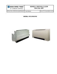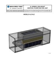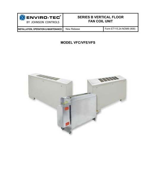
SERIES B VERTICAL FLOOR FAN COIL UNIT MOdEL ... - Enviro-Tec
SERIES B VERTICAL FLOOR FAN COIL UNIT MOdEL ... - Enviro-Tec
SERIES B VERTICAL FLOOR FAN COIL UNIT MOdEL ... - Enviro-Tec

Create successful ePaper yourself
Turn your PDF publications into a flip-book with our unique Google optimized e-Paper software.
BY JOHNSON CONTROLS<br />
Installation, Operation & Maintenance<br />
<strong>SERIES</strong> B <strong>VERTICAL</strong> <strong>FLOOR</strong><br />
<strong>FAN</strong> <strong>COIL</strong> <strong>UNIT</strong><br />
New Release Form ET115.24-NOM9 (908)<br />
Model VFC/VFE/VFS
FORM ET115.24-NOM9 (908)<br />
TABLE OF CONTENTS<br />
TABLE OF CONTENTS..................................................................................................................2<br />
SAFETY SYMBOLS ......................................................................................................................3<br />
SAFETY CONSIDERATIONS.........................................................................................................4<br />
SECTION 1 - RECEIPT & INITIAL INSTALLATION......................................................................5<br />
VF <strong>SERIES</strong> B FEATURES.......................................................................................................................5<br />
PREFACE................................................................................................................................................5<br />
UNPACKING & INSPECTION ................................................................................................................6<br />
HANDLING & INSTALLATION ...............................................................................................................6<br />
COOLING/HEATING MEDIUM CONNECTIONS ...................................................................................7<br />
DUCTWORK CONNECTIONS ...............................................................................................................9<br />
ELECTRICAL CONNECTIONS ..............................................................................................................9<br />
SECTION 2 - START-UP .............................................................................................................10<br />
GENERAL .............................................................................................................................................10<br />
COOLING/HEATING SYSTEM .............................................................................................................10<br />
AIR SYSTEM BALANCING ..................................................................................................................10<br />
WATER SYSTEM BALANCING ...........................................................................................................10<br />
CONTROLS OPERATION ....................................................................................................................11<br />
MOTOR AND <strong>FAN</strong> DATA.......................................................................................................................11<br />
EXAMPLE WIRING DIAGRAMS...........................................................................................................12<br />
SECTION 3 - NORMAL OPERATION & PERIODIC MAINTENANCE.........................................14<br />
GENERAL .............................................................................................................................................14<br />
MOTOR/BLOWER ASSEMBLY ...........................................................................................................14<br />
<strong>COIL</strong> ......................................................................................................................................................14<br />
ELECTRIC RESISTANCE HEATER ASSEMBLY ................................................................................14<br />
<strong>FAN</strong> DECK.............................................................................................................................................14<br />
ELECTRICAL WIRING & CONTROLS ................................................................................................14<br />
VALVES & PIPING................................................................................................................................15<br />
FILTERS, THROWAWAY ......................................................................................................................15<br />
REPLACEMENT PARTS ......................................................................................................................15<br />
FALSE BACK ASSEMBLY....................................................................................................................16<br />
SUB BASE ASSEMBLY AND LEVELING LEGS..................................................................................17<br />
SECTION 4 - INSPECTION, INSTALLATION & START-UP CHECKLIST..................................18<br />
SECTION 5 - DIMENSIONAL DRAWINGS..................................................................................19<br />
MODEL VFC - CONCEALED <strong>FAN</strong> <strong>COIL</strong> <strong>UNIT</strong>.....................................................................................19<br />
MODEL VFE - EXPOSED <strong>FAN</strong> <strong>COIL</strong> <strong>UNIT</strong> W/ STAMPED SUPPLY GRILLE......................................20<br />
MODEL VFS - EXPOSED SLOPE TOP <strong>FAN</strong> <strong>COIL</strong> <strong>UNIT</strong> W/ STAMPED SUPPLY AIR GRILLE.........21<br />
MODEL VF - OUTSIDE AIR INLET LOCATION...................................................................................22<br />
MODEL VFC - STANDARD DECORATOR WALL PANEL W/ STAMPED<br />
RETURN AIR GRILLE...........................................................................................................................23<br />
MODEL VFC - STANDARD DECORATOR WALL PANEL W/ STAMPED<br />
SUPPLY & RETURN AIR GRILLE........................................................................................................24<br />
MODEL VF - OUTSIDE AIR WALL BOX ASSEMBLY..........................................................................25<br />
MODEL VFE/VFS - STAMPED LOUVER RETURN AIR GRILLE........................................................26<br />
MODEL VFE - EXPOSED <strong>FAN</strong> <strong>COIL</strong> <strong>UNIT</strong> W/ STAMPED SUPPLY GRILLE &<br />
10” END POCKET EXTENSION...........................................................................................................27<br />
MODEL VF - ELECTRIC ENTRY & PIPING WALL PENETRATION LOCATIONS..............................28<br />
2<br />
Johnson Controls
FORM ET115.24-NOM9 (908)<br />
SAFETY SYMBOLS<br />
The following symbols are used in this document to alert the reader to areas of potential hazard:<br />
DANGER indicates an imminently<br />
hazardous situation which, if not<br />
avoided, will result in death or serious<br />
injury.<br />
WARNING indicates a potentially<br />
hazardous situation which, if not<br />
avoided, could result in death or serious<br />
injury.<br />
CAUTION identifies a hazard which<br />
could lead to damage to the machine,<br />
damage to other equipment and/or<br />
environmental pollution. Usually an<br />
instruction will be given, together with<br />
a brief explanation.<br />
NOTE is used to highlight additional<br />
information which may be helpful to<br />
you.<br />
Johnson Controls 3
FORM ET115.24-NOM9 (908)<br />
SAFETY CONSIDERATIONS<br />
The equipment covered by this manual is designed for<br />
safe and reliable operation when installed and operated<br />
within its design specification limits. To avoid personal<br />
injury or damage to equipment or property while<br />
installing or operating this equipment, it is essential<br />
that qualified, experienced personnel perform these<br />
functions using good judgment and safe practices. See<br />
the following cautionary statements.<br />
ELECTRICAL SHOCK HAZARDS.<br />
All power must be disconnected prior<br />
to installation and serving this equipment.<br />
More than one source of power<br />
may be present. Disconnect all power<br />
sources to avoid electrocution or shock<br />
injuries.<br />
MOVING PARTS HAZARDS. Motor<br />
and Blower must be disconnected<br />
prior to opening access panels. Motors<br />
can start automatically, disconnect<br />
all power and control circuits prior to<br />
servicing to avoid serious crushing or<br />
dismemberment injuries.<br />
HOT PARTS HAZARDS. Electric Resistance<br />
heating elements must be disconnected<br />
prior to servicing. Electric<br />
Heaters may start automatically, disconnect<br />
all power and control circuits<br />
prior to servicing to avoid burns.<br />
Check that the unit assembly and component<br />
weights can be safely supported<br />
by rigging and lifting equipment.<br />
All assemblies must be adequately<br />
secured during lifting and rigging by<br />
temporary supports and restraints until<br />
equipment is permanently fastened<br />
and set in its final location.<br />
All unit temporary and permanent<br />
supports must be capable of safely<br />
supporting the equipment’s weight and<br />
any additional live or dead loads that<br />
may be encountered. All supports must<br />
be designed to meet applicable local<br />
codes and ordinances.<br />
All fastening devices must be designed<br />
to mechanically lock the assembly in<br />
place without the capability of loosening<br />
or breaking away due to system<br />
operation and vibration.<br />
Secure all dampers when servicing<br />
damper, actuator or linkages. Dampers<br />
may activate automatically, disconnect<br />
control circuits or pneumatic control<br />
systems to avoid injury.<br />
Protect adjacent flammable materials<br />
when brazing, Use flame and heat protection<br />
barriers where needed. Have<br />
fire extinguisher available and ready<br />
for immediate use.<br />
4<br />
Johnson Controls
FORM ET115.24-NOM9 (908)<br />
SECTION 1 - RECEIPT & INITIAL INSTALLATION<br />
VF <strong>SERIES</strong> B FEATURES<br />
(Provided with unit mounted t-stat)<br />
LD13943<br />
PREFACE<br />
ENVIRO-TEC ® fan coils represent a prudent investment<br />
which can, with proper installation, operation, and<br />
regular maintenance, give trouble-free operation and<br />
long service.<br />
Your equipment is initially protected under the<br />
manufacturer’s standard warranty; however, this<br />
warranty is provided under the condition that the steps<br />
outlined in this manual for initial inspection, proper<br />
installation, regular periodic maintenance, and everyday<br />
operation of the equipment be followed in detail. This<br />
manual should be fully reviewed in advance of any<br />
actual work being done on the equipment. Should<br />
any questions arise, please contact your local Sales<br />
Representative or the factory BEFORE proceeding.<br />
The equipment covered by this manual is available with<br />
a vast variety of options and accessories. Consult the<br />
approved unit submittal, order acknowledgement, and<br />
other manuals for details on the options and accessories<br />
provided with the equipment on each project.<br />
No attempt should be made to handle,<br />
install, or service any unit without<br />
following safe practices regarding<br />
mechanical equipment.<br />
Johnson Controls 5
FORM ET115.24-NOM9 (908)<br />
6<br />
All power must be disconnected before<br />
any installation or service should be attempted.<br />
More than one power source<br />
may be supplied to a unit. Power to<br />
remote mounted control devices may<br />
not be supplied through the unit.<br />
Never wear bulky or loose fitting clothing<br />
when working on any mechanical<br />
equipment. Gloves should only be<br />
worn when required for proper protection<br />
from heat or other possible injury.<br />
Safety glasses or goggles should<br />
always be worn when drilling, cutting,<br />
or working with chemicals such as<br />
refrigerants or lubricants.<br />
Never pressurize any equipment beyond<br />
specified operating pressures.<br />
Always pressure test with some inert<br />
fluid or gas such as clear water or dry<br />
nitrogen to avoid possible damage or<br />
injury in the event of a leak or component<br />
failure during testing.<br />
Always protect adjacent flammable<br />
material when welding or soldering.<br />
Use suitable heat shield material to<br />
contain sparks or drops of solder.<br />
Have fire extinguisher available for<br />
use when welding or brazing.<br />
The manufacturer assumes no responsibility for personal<br />
injury or property damage resulting from improper<br />
or unsafe practices during the handling, installation,<br />
service, or operation of any equipment.<br />
UNPACKING & INSPECTION<br />
All units are carefully inspected at the factory throughout<br />
the manufacturing process under a strict detailed quality<br />
assurance program, and where possible, all major<br />
components and subassemblies are carefully tested for<br />
proper operation and verified to be in full compliance<br />
with the factory manufacturing documents. Customer<br />
furnished components such as control valves, switches<br />
and DDC controls are not factory tested.<br />
Each unit is carefully packaged for shipment to avoid<br />
damage during normal transport and handling. The<br />
equipment should always be stored in a dry place in the<br />
proper orientation as marked on the carton.<br />
All shipments are made F.O.B. factory and it is the<br />
responsibility of the receiving party to inspect the<br />
equipment upon arrival. Any obvious damage to the<br />
carton and/or its contents should be recorded on the bill<br />
of lading and a claim should be filed with the freight<br />
carrier.<br />
After determining the condition of the carton exterior,<br />
carefully remove each unit from the carton and inspect<br />
for hidden damage. At this time check to make sure that<br />
“furnished only” items such as switches, thermostats,<br />
etc. are accounted for. Any hidden damage should be<br />
recorded and immediately reported to the carrier and a<br />
claim filed as before. In the event a claim for shipping<br />
damage is filed, the unit, shipping carton, and all packing<br />
must be retained for physical inspection by the freight<br />
carrier.<br />
All equipment should be stored in the factory-shipping<br />
carton with internal packing in place until installation.<br />
At the time of receipt, the equipment type and<br />
arrangement should be verified against the order<br />
documents. Should any discrepancy be found, the local<br />
Sales Representative should be notified immediately<br />
so that the proper action may be instituted. Should<br />
any question arise concerning warranty repairs, the<br />
factory must be notified BEFORE any corrective<br />
action is taken. Where local repairs or alterations can<br />
be accomplished, the factory must be fully informed as<br />
to the extent and expected cost of those repairs before<br />
work is begun. Where factory operations are required,<br />
the factory must be contacted for authorization to return<br />
equipment and a Return Authorization Number will be<br />
issued. Unauthorized return shipments of equipment<br />
and shipments not marked with an authorization number<br />
will be refused. In addition, the manufacturer will not<br />
accept any claims for unauthorized expenses.<br />
HANDLING & INSTALLATION<br />
While all equipment is designed for durability and<br />
fabricated for sturdy construction and may present a<br />
rugged appearance, great care must be taken to assure<br />
that no force or pressure be applied to the coil, piping<br />
or drain stub-outs during handling. Also, depending<br />
on the options and accessories, some units could<br />
contain delicate components that may be damaged by<br />
improper handling. Wherever possible, all units should<br />
be maintained in an upright position and handled by<br />
the chassis as close as possible to the mounting point<br />
locations.<br />
Johnson Controls
FORM ET115.24-NOM9 (908)<br />
In the case of a full cabinet unit, the unit must obviously<br />
be handled by the exterior casing. This is acceptable<br />
providing the unit is again maintained in an upright<br />
position and no impact forces are applied that may<br />
damage internal components or painted surfaces. The<br />
equipment covered in this manual IS NOT suitable<br />
for outdoor installations. The equipment should never<br />
be stored or installed where it may be subjected to a<br />
hostile environment such as rain, snow, or extreme<br />
temperatures.<br />
During and after installation, special care must be taken<br />
to prevent foreign material such as paint, plaster, and<br />
drywall dust from being deposited in the drain pan or<br />
on the motor or blower wheels. Failure to do so may<br />
have serious adverse effects on unit operation and in<br />
the case of the motor and blower assembly, may result<br />
in immediate or premature failure. All manufacturers’<br />
warranties are void if foreign material is deposited on<br />
the motor or blower wheels of any unit. Some units and/<br />
or job conditions may require some form of temporary<br />
covering during construction.<br />
While the manufacturer does not become involved<br />
in the design and selection of support methods and<br />
components, it should be noted that unacceptable<br />
system operating characteristics and/or performance<br />
may result from improper or inadequate unit structural<br />
support. In addition, adequate clearance must be<br />
provided for service and removal of the equipment and<br />
its accessory components. Anchoring the equipment in<br />
place is accomplished by using the mounting points<br />
provided and positioning the unit to maintain the unit<br />
on a LEVEL plane. The drain pan is internally sloped<br />
toward the outlet connection. Care must be taken to<br />
insure that the unit drain pan does not slope away from<br />
the outlet connection.<br />
The unit's drain pan is factory sloped<br />
toward the drain connection when the<br />
unit is installed level and plumb.<br />
Vertical units are designed to be floor mounted or<br />
otherwise supported from below and bolted to the wall<br />
structure through the mounting holes provide in the<br />
chassis. Vertical concealed units are designed to be<br />
floor mounted or otherwise supported from below and<br />
may be anchored directly through the cabinet back.<br />
Units with leveling legs must be anchored through the<br />
cabinet back.<br />
If equipped with optional leveling legs, the legs can<br />
be adjusted with a wrench before anchoring the unit<br />
in place.<br />
The type of mounting device is a matter of choice,<br />
however the mounting point should always be that<br />
provided in the chassis, or cabinet. Refer to the unit<br />
product drawing for mounting hole location and<br />
sizes.<br />
If equipped with optional falseback spacers or subbases,<br />
these accessories must first be assembled and mounted<br />
to the unit before anchoring.<br />
After mounting the unit, it is then ready for the various<br />
service connections such as water, drain and electrical.<br />
At this time it should be verified that the proper types<br />
of service are actually provided to the unit.<br />
On those units requiring chilled water and/or hot water,<br />
the proper line size and water temperature should be<br />
available to the unit. In the case of refrigerant cooling,<br />
the proper line size and refrigerant type should be<br />
available at the unit. The auxiliary drain pan is shipped<br />
loose for field installation. See the Auxiliary Drain Pan<br />
Installation Details for instructions (next page). On<br />
units with steam heating coils, the proper line sizing<br />
and routing should be verified and the maximum steam<br />
pressure applied to the unit should never exceed 15<br />
psig. The drain piping and steam trap should be sized<br />
and routed to allow for proper condensate flow. The<br />
electrical service to the unit should be compared to<br />
the unit nameplate to verify compatibility. The routing<br />
and sizing of all piping, and the type and sizing of all<br />
wiring and other electrical components such as circuit<br />
breakers, disconnect switches, etc. should be determined<br />
by the individual job requirements and should not be<br />
based on the size and/or type of connection provided<br />
on the equipment. All installations should be made in<br />
compliance with all governing codes and ordinances.<br />
Compliance with all codes is the responsibility of the<br />
installing contractor.<br />
COOLING/HEATING MEDIUM CONNECTIONS<br />
Toxic residues and loose particles<br />
resulting from manufacturing and<br />
field piping techniques such as joint<br />
compounds, soldering flux, and metal<br />
shavings may be present in the unit<br />
and the piping system. Special consideration<br />
must be given to system<br />
cleanliness when connecting to solar,<br />
domestic or potable water systems.<br />
Johnson Controls 7
FORM ET115.24-NOM9 (908)<br />
Submittals and Product Catalogs detailing unit operation,<br />
controls, and connections should be thoroughly<br />
reviewed BEFORE beginning the connection of the<br />
various cooling and/or heating mediums to the unit. All<br />
documentation may be found at www.enviro-tec.com.<br />
All accessory valve packages should be installed as<br />
required, and all service valves should be checked for<br />
proper operation.<br />
If coil and valve package connections are to be made<br />
with “sweat” or solder joint, care should be taken to<br />
assure that no components in the valve package are<br />
subjected to a high temperature which may damage seals<br />
or other materials. Many two-position electric control<br />
valves, depending on valve operation, are provided with<br />
a manual-opening lever. This lever should be placed<br />
in the “open” position during all soldering or brazing<br />
operations. Valve bodies should be wrapped with a wet<br />
rag to help dissipate heat encountered during brazing.<br />
If the valve package connection at the coil is made with<br />
a union, the coil side of the union must be prevented<br />
from twisting (“backed up”) during tightening to prevent<br />
damage to the coil tubing. Over-tightening must be<br />
avoided to prevent distorting the union seal surface and<br />
destroying the union.<br />
In the case of field installed valves and piping, the<br />
chilled water valve cluster (or expansion valve on DX<br />
units) should be installed in such a way that any dripping<br />
or sweating is contained in the auxiliary drain pan or<br />
other device.<br />
After the connections are completed, the system should<br />
then be tested for leaks. Since some components are not<br />
designed to hold pressure with a gas, hydronic systems<br />
should be tested with water.<br />
All water coils must be protected from<br />
freezing after initial filling with water.<br />
Even if the system is drained, unit coils<br />
may still hold enough water to cause<br />
damage when exposed to temperatures<br />
below freezing.<br />
Refrigerant systems should be tested with dry nitrogen<br />
rather than air to prevent the introduction of moisture<br />
into the system. In the event that leaking or defective<br />
components are discovered, the Sales Representative<br />
must be notified BEFORE any repairs are attempted.<br />
All leaks should be repaired before proceeding with<br />
the installation.<br />
UPPER SUPPORT TABS<br />
SEE NOTE 4<br />
FLOAT SWITCH MOUNT<br />
SEE NOTE 4<br />
LOWER SUPPORT<br />
TABS<br />
SECTION A-A<br />
NOTE:<br />
INSTALLING CONTRACTOR MUST ASSURE<br />
THAT THE CONNECTED DRAIN PIPING<br />
MAINTAINS THE PROPER PAN ORIENTATION.<br />
NOTES:<br />
1. BEND LOWER SUPPORT TABS DOWN 90º.<br />
2. BEND UPPER SUPPORT TABS UP 90º.<br />
3. POSITION DRAIN PAN IN PLACE AND THEN BEND UPPER SUPPORT TABS DOWN UNTIL PAN IS SECURE.<br />
4. BEND FLOAT SWITCH MOUNT OUT 90º IF NEEDED.<br />
5. STANDARD PAN SHOWN, TYPICAL FOR EXTENDED PAN. LD13944<br />
8<br />
Johnson Controls
FORM ET115.24-NOM9 (908)<br />
After system integrity has been established the piping<br />
should be insulated in accordance with the project<br />
specifications. ALL chilled water piping and valves or<br />
refrigerant suction piping not located over drain pans<br />
must be insulated to prevent damage from sweating.<br />
This includes factory and field piping inside the unit<br />
cabinet.<br />
The drain should always be connected and piped to an<br />
acceptable disposal point. For proper moisture carryoff,<br />
the drain piping should be sloped away from the<br />
unit at least 1/8" per foot. A drain trap may be required<br />
by local codes and it is strongly recommended for odor<br />
containment.<br />
DUCTWORK CONNECTIONS<br />
All ductwork and/or supply and return grilles should<br />
be installed in accordance with the project plans and<br />
specifications. If not included on the unit or furnished<br />
from the factory, supply and return grilles should be<br />
provided as recommended in the product catalog.<br />
All units must be installed in non-combustible areas.<br />
Some models are designed to be connected to duct-work<br />
with a MINIMUM amount of external static pressure.<br />
These units may be damaged by operation without the<br />
proper ductwork connected. Consult the approved<br />
submittals and the product catalog for unit external<br />
static pressure limitations.<br />
Units provided with outside air for ventilation should<br />
have some form of low temperature protection to<br />
prevent coil freeze-up.<br />
It should be noted that none of these methods would<br />
adequately protect a coil in the event of power failure.<br />
The safest method of freeze protection is to use glycol<br />
in the proper percent solution for the coldest expected<br />
air temperature.<br />
ELECTRICAL CONNECTIONS<br />
The unit nameplate lists the unit electrical characteristics<br />
such as the required supply voltage, fan and heater<br />
amperage and required circuit ampacities. The unitwiring<br />
diagram shows all unit and field wiring. Since<br />
each project is different and each unit on a project may<br />
be different, the installer must be familiar with the<br />
wiring diagram and nameplate on the unit BEFORE<br />
beginning any wiring. All components furnished for<br />
field installation, by either the factory or the controls<br />
contractor should be located and checked for proper<br />
function and compatibility. All internal components<br />
should be checked for shipping damage and all electrical<br />
connections should be tightened to minimize problems<br />
during start-up.<br />
Any devices such as fan switches or thermostats<br />
that have been furnished from the factory for field<br />
installation must be wired in strict accordance with the<br />
applicable wiring diagrams. Failure to do so could result<br />
in personal injury or damage to components and will<br />
void all manufacturers’ warranties.<br />
The fan motor(s) should never be controlled by any<br />
wiring or device other than the factory furnished<br />
switch, thermostat/switch combination, without factory<br />
authorization.<br />
All field wiring should be done in accordance with<br />
governing codes and ordinances. Any modification of<br />
the unit wiring without factory authorization will result<br />
in voiding of all factory warranties and will nullify any<br />
agency listings.<br />
The manufacturer assumes no responsibility for any<br />
damages and/or injuries resulting from improperly field<br />
installed or wired components.<br />
The manufacturer assumes no responsibility for<br />
undesirable system operation due to improper<br />
design, equipment or component selection, and/or<br />
installation of ductwork, grilles, and other field supplied<br />
components.<br />
Johnson Controls 9
FORM ET115.24-NOM9 (908)<br />
SECTION 2 - START-UP<br />
GENERAL<br />
Before beginning any start-up operation, the startup<br />
personnel should familiarize themselves with the<br />
unit, options and accessories, and control sequence to<br />
understand the proper system operation. All personnel<br />
should have a good working knowledge of general<br />
start-up procedures and have the appropriate start-up<br />
and balancing guides available for consultation.<br />
The initial step in any startup operation should be a final<br />
visual inspection. All equipment, plenums, duct-work,<br />
and piping should be inspected to verify that all systems<br />
are complete and properly installed and mounted, and<br />
that no debris or foreign articles such as paper or drink<br />
cans are left in the units or other areas. Each unit should<br />
be checked for loose wires, free blower wheel operation,<br />
and loose or missing access panels or doors. Except as<br />
required during start-up and balancing operations, no<br />
fan coil units should be operated without all the proper<br />
ductwork attached, supply and return grilles in place,<br />
and all access doors and panels in place and secure.<br />
A clean filter of the proper size and type must also be<br />
installed. Failure to do so could result in damage to the<br />
equipment or building and furnishings, and/or void all<br />
manufacturers’ warranties.<br />
COOLING/HEATING SYSTEM<br />
Prior to the water system start-up and balancing, the<br />
chilled/hot water systems should be flushed to clean<br />
out dirt and debris, which may have collected in the<br />
piping during construction. During this procedure,<br />
all unit service valves must be in the closed position.<br />
This prevents foreign matter from entering the unit and<br />
clogging the valves and metering devices. Strainers<br />
should be installed in the piping mains to prevent<br />
this material from entering the units during normal<br />
operation.<br />
During system filling, air venting from the unit is<br />
accomplished by the use of the standard, manual or<br />
optional automatic air vent fitting installed on the coil.<br />
In the case of the manual air vent fitting, the screw<br />
should be turned counterclockwise no more than 1-1/2<br />
turns to operate the air vent. Automatic air vents may<br />
be unscrewed one turn counterclockwise to speed initial<br />
venting but should be screwed in for automatic venting<br />
after start-up operations.<br />
The air vent provided on the unit is not<br />
intended to replace the main system air<br />
vents and may not release air trapped<br />
in other parts of the system. Inspect the<br />
entire system for potential air traps and<br />
vent those areas as required, independently.<br />
In addition, some systems may<br />
require repeated venting over a period<br />
of time to properly eliminate air from<br />
the system.<br />
AIR SYSTEM BALANCING<br />
All ductwork must be complete and connected, and all<br />
grilles, filters, access doors and panels must be properly<br />
installed to establish actual system operating conditions<br />
BEFORE beginning air balancing operations.<br />
Each individual unit and attached ductwork is a unique<br />
system with its own operating characteristics. For this<br />
reason, balance specialists who are familiar with all<br />
procedures required to properly establish air distribution<br />
and fan system operating conditions normally do air<br />
balancing. Unqualified personnel should not attempt<br />
these procedures. Exposed units with no ductwork do<br />
not require air balancing other than selecting the desired<br />
fan speed.<br />
After the proper system operation is established,<br />
the actual unit air delivery and the actual fan motor<br />
amperage draw for each unit should be recorded in<br />
a convenient place for future reference such as the<br />
inspection, installation, & start-up check sheet, a copy<br />
of which is provided at the back of this manual. Contact<br />
the Sales Representative or the factory for additional<br />
copies of this sheet.<br />
WATER SYSTEM BALANCING<br />
A complete knowledge of the hydronic system, its<br />
components, and controls is essential to proper water<br />
system balancing and this procedure should not be<br />
attempted by unqualified personnel. The system must<br />
be complete and all components must be in operating<br />
condition BEFORE beginning water system balancing<br />
operations.<br />
10<br />
Johnson Controls
FORM ET115.24-NOM9 (908)<br />
Each hydronic system has different operating<br />
characteristics depending on the devices and controls<br />
in the system. The actual balancing technique may vary<br />
from one system to another.<br />
After the proper system operation is established, the<br />
appropriate system operating conditions such as various<br />
water temperatures and flow rates should be recorded<br />
in a convenient place for future reference such as the<br />
inspection, installation, & start-up check sheet, a copy<br />
of which is provided on the back of this manual. Contact<br />
the Sales Representative or the factory for additional<br />
copies of this sheet.<br />
Before and during water system balancing, conditions<br />
may exist which can result in noticeable water<br />
noise or undesired valve operation due to incorrect<br />
system pressures. After the entire system is balanced,<br />
these conditions will not exist on properly designed<br />
systems.<br />
CONTROLS OPERATION<br />
Before proper control operation can be verified all other<br />
systems must be in proper operation. The correct water<br />
and air temperatures must be present for the control<br />
function being tested. Some controls and features are<br />
designed to not operate under certain conditions.<br />
A wide range of controls and electrical options and<br />
accessories may be used with the equipment covered<br />
in this manual. Consult the approved unit submittals,<br />
order acknowledgement, and other manuals for detailed<br />
information regarding each individual unit and its<br />
controls. Since controls and features may vary from<br />
one unit to another, care should be taken to identify<br />
the controls to be used on each unit and their proper<br />
control sequence. Information provided by component<br />
manufacturers regarding installation, operation, and<br />
maintenance of their individual controls is available<br />
upon request.<br />
<strong>UNIT</strong><br />
SIZE<br />
20<br />
25<br />
30<br />
40<br />
50<br />
60<br />
<strong>FAN</strong><br />
SPEED<br />
MOTOR<br />
H.P.<br />
(QTY.)<br />
High (1) 1/30<br />
MOTOR AND <strong>FAN</strong> DATA<br />
# OF<br />
<strong>FAN</strong>S<br />
115VOLTS 208-230 VOLTS 277 VOLTS<br />
AMPS WATTS AMPS WATTS AMPS WATTS<br />
0.8 57 0.6 77 0.3 71<br />
Medium (1) 1/50 1 0.4 39 0.3 49 0.3 48<br />
Low (1) 1/60 0.3 33 0.3 43 0.3 41<br />
High (1) 1/15<br />
1.1 125 0.5 120 0.5 120<br />
Medium (1) 1/30 1 0.9 90 0.3 80 0.3 80<br />
Low (1) 1/60 0.5 60 0.2 60 0.2 60<br />
High (1) 1/10<br />
1.9 165 0.8 158 0.8 162<br />
Medium (1) 1/30 2 0.8 76 0.3 75 0.5 65<br />
Low (1) 1/60 0.5 47 0.2 54 0.4 41<br />
High (1) 1/6<br />
2.5 261 1.4 284 1.0 254<br />
Medium (1) 1/12 2 1.5 162 0.5 171 0.5 152<br />
Low (1) 1/40 0.8 75 0.4 79 0.3 74<br />
High<br />
Medium<br />
Low<br />
(1) 1/8<br />
High (1) 1/6<br />
1.7 215 0.9 216 0.8 214<br />
(1) 1/6 2.5 257 1.4 233 1.0 255<br />
(1) 1/15 1.3 145 0.6 109 0.5 132<br />
3<br />
(1) 1/12 1.5 156 0.5 106 0.5 151<br />
(1) 1/40 0.3 69 0.3 63 0.3 86<br />
(1) 1/40 0.6 75 0.3 62 0.3 84<br />
5.0 522 2.8 568 2.0 508<br />
Medium (1) 1/12 4 3.0 324 1.0 342 1.0 304<br />
Low (1) 1/40 1.2 150 0.6 158 0.6 148<br />
NOTES:<br />
1. Motor electrical data is nameplated data. Actual data will vary with application.<br />
2. 230 volt motor is nameplated for 208-230/1/60. Use 230 volt motor data for 208 volt applications.<br />
3. Unit size 30, 208-230 and 277 volt motors are 1/12 HP at high tap.<br />
Johnson Controls 11
FORM ET115.24-NOM9 (908)<br />
EXAMPLE WIRING DIAGRAMS<br />
"Example Wiring Diagram - Typical 24 VAC Control Drawing (Refer to unit control enclosure for actual order-specific drawing)"<br />
84-10-0615-REV05<br />
12<br />
Johnson Controls
FORM ET115.24-NOM9 (908)<br />
EXAMPLE WIRING DIAGRAMS (Continued)<br />
"Example Wiring Diagram - Typical 24 VAC Control Drawing (Refer to unit control enclosure for actual order-specific drawing)"<br />
84-10-0205-REV05<br />
Johnson Controls 13
FORM ET115.24-NOM9 (908)<br />
SECTION 3 - NORMAL OPERATION & PERIODIC MAINTENANCE<br />
GENERAL<br />
Each unit on a job will have its own unique operating<br />
environment and conditions that may dictate a<br />
maintenance schedule for that unit that is different<br />
from other equipment on the job. A formal schedule of<br />
regular maintenance and an individual unit log should<br />
be established and maintained. This will help to achieve<br />
the maximum performance and service life of each unit<br />
on the job.<br />
Information regarding safety precautions<br />
contained in the preface at the<br />
beginning of this manual should be<br />
followed during any service and maintenance<br />
operations.<br />
For more detailed information concerning service<br />
operations, consult your Sales Representative or the<br />
Factory.<br />
MOTOR/BLOWER ASSEMBLY<br />
The type of fan operation is determined by the control<br />
components and their method of wiring, and may vary<br />
from unit to unit. Refer to the wiring diagram for each<br />
unit for that unit’s individual operating characteristics.<br />
Motors are permanently lubricated, PSC type and do not<br />
require field lubrication.<br />
Should the assembly require more extensive service,<br />
the motor/blower assembly may be removed from the<br />
unit to facilitate such operations as motor or blower<br />
wheel/housing replacement, etc. Dirt and dust should<br />
not be allowed to accumulate on the blower wheel or<br />
housing. This can result in an unbalanced blower wheel<br />
condition that can damage a blower wheel or motor.<br />
The wheel and housing may be cleaned periodically<br />
using a vacuum cleaner and a brush taking care not to<br />
dislodge the factory balancing weights on the blower<br />
wheel blades.<br />
<strong>COIL</strong><br />
Coils may be cleaned in place by removing the motor/<br />
blower assemblies and brushing the entering air face<br />
between fins with a stiff brush. Cleaning with a vacuum<br />
cleaner should follow brushing. If a compressed air<br />
source is available, the coil may also be cleaned by<br />
blowing air through the coil fins from the leaving<br />
air face. Vacuuming should again follow this. Units<br />
provided with the proper type of air filters, replaced<br />
regularly, will require coil cleaning.<br />
ELECTRIC RESISTANCE HEATER ASSEMBLY<br />
Electric resistance heaters typically require no normal<br />
periodic maintenance when unit air filters are changed<br />
properly. Other conditions and equipment may affect the<br />
operation and service life in the system. The two most<br />
important operating conditions for an electric heater are<br />
proper airflow and proper supply voltage. High supply<br />
voltage and/or poorly distributed or insufficient airflow<br />
over the element will result in element overheating. This<br />
condition may result in the heater cycling on the high<br />
limit thermal cutout<br />
Sheathed type heaters provided have an automatic<br />
reset switch with a back-up high limit thermal switch.<br />
Automatic reset switches are as the name implies; they<br />
reset automatically after the heater has cooled down.<br />
High limit thermal switches must be replaced once the<br />
circuit has been broken. The high limit thermal cutout<br />
device is a safety device only and is not intended for<br />
continuous operation. With proper unit application and<br />
during normal operation, the high limit thermal cutout<br />
will not operate. This device only operates when some<br />
problem exists and ANY condition that causes high limit<br />
cutout MUST be corrected immediately. High supply<br />
voltage also causes excessive amperage draw and may<br />
result in tripping of the circuit breaker or blowing of<br />
the fuses on the incoming power supply.<br />
<strong>FAN</strong> DECK<br />
The fan/drain pan assembly is easily removable for<br />
service access to motors and blowers at, or away from,<br />
the unit.<br />
ELECTRICAL WIRING & CONTROLS<br />
The electrical operation of each unit is determined by<br />
the components and wiring of the unit and may vary<br />
from unit to unit. Consult the wiring diagram for the<br />
actual type and number of controls provided on each<br />
unit. The integrity of all electrical connections should be<br />
verified at least twice during the first year of operation.<br />
Afterwards, all controls should be inspected regularly<br />
for proper operation. Some components may experience<br />
erratic operation or failure due to age. Wall thermostats<br />
may also become clogged with dust and lint and should<br />
be periodically inspected and cleaned to provide reliable<br />
operation.<br />
14<br />
Johnson Controls
FORM ET115.24-NOM9 (908)<br />
When replacing any components such as fuses,<br />
contactors, or relays, use only the exact type, size, and<br />
voltage component as furnished from the factory. Any<br />
deviation without factory authorization could result<br />
in personnel injury or damage to the unit and will<br />
void all factory warranties. All repair work should be<br />
done in such a manner as to maintain the equipment in<br />
compliance with governing codes and ordinances or<br />
testing agency listings.<br />
More specific information regarding the use and<br />
operating characteristics of the standard controls offered<br />
by this manufacturer is contained in other manuals.<br />
VALVES & PIPING<br />
No formal maintenance is required on the valve package<br />
components most commonly used with fan coil units<br />
other than a visual inspection for possible leaks in the<br />
course of other normal periodic maintenance. In the<br />
event that a valve should need replacement, the same<br />
precautions taken during the initial installation to protect<br />
the valve package from excessive heat should also be<br />
used during replacement.<br />
FILTERS, THROWAWAY<br />
The type of throwaway filter most commonly used on<br />
fan coil units should be replaced on a regular basis.<br />
The time interval between each replacement should<br />
be established based on regular inspection of the filter<br />
and should be recorded in the log for each unit. Refer<br />
to the product catalog for the recommended filter size<br />
for each product type and size. If the replacement<br />
filters are not purchased from the factory, the filters<br />
used should be the same type and size as that furnished<br />
from or recommended by the factory. Pleated media<br />
or extended surface filters should not be used since the<br />
high air pressure drops encountered with these types<br />
of filters is not compatible with the type of fan coil<br />
unit covered in this manual. Consult the factory for<br />
applications using filter types other than the factory<br />
standard or optional product.<br />
DRAIN<br />
The drain should be checked before initial start-up and<br />
at the beginning of each cooling season to assure that the<br />
lines are clear. If it is clogged, steps should be taken to<br />
clear the debris so that condensate will flow easily.<br />
Periodic checks of the drain should be made during the<br />
cooling season to maintain a free flowing condensate.<br />
Should the growth of algae and/or bacteria be a concern,<br />
consult an air conditioning and refrigeration supply<br />
organization familiar with local conditions for chemicals<br />
available to control these agents.<br />
REPLACEMENT PARTS<br />
Factory replacement parts should be used wherever<br />
possible to maintain the unit performance and<br />
operating characteristics and the testing agency listings.<br />
Replacement parts may be purchased through the local<br />
Sales Representative.<br />
Contact the local Sales Representative or the factory<br />
before attempting any unit modifications. Any<br />
modifications not authorized by the factory could result<br />
in personnel injury and damage to the unit and could<br />
void all factory warranties.<br />
When ordering parts, the following information must be<br />
supplied to ensure proper part identification:<br />
1. Complete unit model number.<br />
2. Unit hand connection (right or left hand) while<br />
facing into the return air stream.<br />
3. Complete part description including any numbers.<br />
On warranty replacements, in addition to the information<br />
previously listed, the project CO # that appears on the<br />
unit nameplate, is required. Contact the factory for<br />
authorization to return any parts such as defective parts<br />
replaced in warranty. All shipments returned to the<br />
factory MUST be marked with a Return Authorization<br />
Number, which is provided by the factory.<br />
All equipment and components sold through the Parts<br />
Department are warranted under the same conditions<br />
as the standard manufacturer's warranty with the<br />
exception that the warranty period is 12 months unless<br />
the component is furnished as warranty replacement.<br />
Parts furnished as warranty replacements are warranted<br />
for the remaining term of the original unit warranties.<br />
Johnson Controls 15
FORM ET115.24-NOM9 (908)<br />
FALSE BACK ASSEMBLY<br />
(Shipped loose and Dissassembled)<br />
Screw, #8 x 1/2” TEK<br />
6 plcs<br />
Bottom Tie Angle<br />
Installs Inside Side<br />
Panels<br />
Screw, #8 x 1/2” TEK<br />
Typ.<br />
Rear Panel<br />
LD13945<br />
16<br />
Johnson Controls
FORM ET115.24-NOM9 (908)<br />
SUB BASE ASSEMBLY AND LEVELING LEGS<br />
LD13946<br />
Johnson Controls 17
FORM ET115.24-NOM9 (908)<br />
SECTION 4 - INSPECTION, INSTALLATION & START-UP CHECKLIST<br />
LD13941<br />
18<br />
Johnson Controls
FORM ET115.24-NOM9 (908)<br />
SECTION 5 - DIMENSIONAL DRAWINGS<br />
MODEL VFC - CONCEALED <strong>FAN</strong> <strong>COIL</strong> <strong>UNIT</strong><br />
51-80004-REV01<br />
Johnson Controls 19
FORM ET115.24-NOM9 (908)<br />
MODEL VFE - EXPOSED <strong>FAN</strong> <strong>COIL</strong> <strong>UNIT</strong> W/ STAMPED SUPPLY GRILLE<br />
51-80003-REV03<br />
20<br />
Johnson Controls
FORM ET115.24-NOM9 (908)<br />
MODEL VFS - EXPOSED SLOPE TOP <strong>FAN</strong> <strong>COIL</strong> <strong>UNIT</strong><br />
W/ STAMPED SUPPLY AIR GRILLE<br />
51-80025-REV02<br />
Johnson Controls 21
FORM ET115.24-NOM9 (908)<br />
MODEL VF - OUTSIDE AIR INLET LOCATION<br />
VFOA-001-REV02<br />
22<br />
Johnson Controls
FORM ET115.24-NOM9 (908)<br />
MODEL VFC - STANDARD DECORATOR WALL PANEL<br />
W/ STAMPED RETURN AIR GRILLE<br />
51-80007-REV01<br />
Johnson Controls 23
FORM ET115.24-NOM9 (908)<br />
MODEL VFC - STANDARD DECORATOR WALL PANEL<br />
W/ STAMPED SUPPLY & RETURN AIR GRILLE<br />
51-80008-REV01<br />
24<br />
Johnson Controls
FORM ET115.24-NOM9 (908)<br />
MODEL VF - OUTSIDE AIR WALL BOX ASSEMBLY<br />
VFWB-001-REV03<br />
Johnson Controls 25
FORM ET115.24-NOM9 (908)<br />
MODEL VFE/VFS - STAMPED LOUVER RETURN AIR GRILLE<br />
51-80031-REV01<br />
26<br />
Johnson Controls
FORM ET115.24-NOM9 (908)<br />
MODEL VFE - EXPOSED <strong>FAN</strong> <strong>COIL</strong> <strong>UNIT</strong><br />
W/ STAMPED SUPPLY GRILLE & 10” END POCKET EXTENSION<br />
51-80010-REV03<br />
Johnson Controls 27
MODEL VF - ELECTRIC ENTRY & PIPING WALL PENETRATION LOCATIONS<br />
VFC<br />
VFF/VFS<br />
VFC<br />
51-80032-REV01<br />
©2008 Johnson Controls, Inc. P.O. Box 423, Milwaukee, WI 53203 www.johnsoncontrols.com<br />
Printed in USA ET115.24-NOM9 (908)<br />
New Release