CSC-3000 series Reset Volume Controllers - Enviro-Tec
CSC-3000 series Reset Volume Controllers - Enviro-Tec
CSC-3000 series Reset Volume Controllers - Enviro-Tec

Create successful ePaper yourself
Turn your PDF publications into a flip-book with our unique Google optimized e-Paper software.
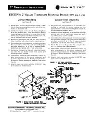
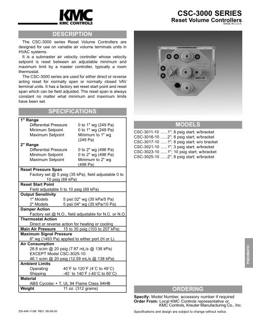
<strong>CSC</strong>-<strong>3000</strong> SERIES<br />
<strong>Reset</strong> <strong>Volume</strong> <strong>Controllers</strong><br />
MADE IN U.S.A.<br />
The <strong>CSC</strong>-<strong>3000</strong> <strong>series</strong> <strong>Reset</strong> <strong>Volume</strong> <strong>Controllers</strong> are<br />
designed for use on variable air volume terminals units in<br />
HVAC systems.<br />
It is a submaster air velocity controller whose velocity<br />
setpoint is reset between an adjustable minimum and<br />
maximum limit by a master controller, typically a room<br />
thermostat.<br />
The <strong>CSC</strong>-<strong>3000</strong> <strong>series</strong> are used for either direct or reverse<br />
acting reset for normally open or normally closed VAV<br />
terminal units. It has a factory set reset start point and reset<br />
span which can be field adjusted. The reset span is always<br />
constant no matter what minimum and maximum limits<br />
have been set.<br />
1" Range<br />
Differential Pressure<br />
Minimum Setpoint<br />
Maximum Setpoint<br />
2" Range<br />
Differential Pressure<br />
Minimum Setpoint<br />
Maximum Setpoint<br />
DS-449-11/98 REV. 06-08-00<br />
DESCRIPTION<br />
SPECIFICATIONS<br />
0 to 1" wg (249 Pa)<br />
0 to 1" wg (249 Pa)<br />
Minimum to 1" wg<br />
(249 Pa)<br />
0 to 2" wg (498 Pa)<br />
0 to 2" wg (498 Pa)<br />
Minimum to 2" wg<br />
(498 Pa)<br />
<strong>Reset</strong> Pressure Span<br />
Factory set @ 5 psig (35 kPa), field adjustable 0 to<br />
10 psig (69 kPa)<br />
<strong>Reset</strong> Start Point<br />
Field adjustable 0 to 10 psig (69 kPa)<br />
Output Sensitivity<br />
1" Models 5 psi/.02" wg (35 kPa/5 Pa)<br />
2" Models 5 psi/.04" wg (35 kPa/10 Pa)<br />
Damper Action<br />
Factory set @ N.O., field adjustable for N.C. or N.O.<br />
Thermostat Action<br />
Direct or reverse action for heating or cooling<br />
Main Air Pressure 15 to 30 psig (103 to 207 kPa)<br />
Maximum Signal Pressure<br />
6" wg (1493 Pa) applied to either port (H or L)<br />
Air Consumption<br />
28.8 scim @ 20 psig (7.87 mL/s @ 138 kPa)<br />
EXCEPT Model <strong>CSC</strong>-3025-10:<br />
46.1 scim @ 20 psig (12.59 mL/s @ 138 kPa)<br />
Ambient Limits<br />
Operating 40˚F to 120˚F (4˚C to 49˚C)<br />
Shipping -40˚ to 140˚F (-40˚C to 60˚C)<br />
Material<br />
ABS Cycolac + T, UL 94 Flame Class 94HB<br />
Weight<br />
11 oz. (312 grams)<br />
MODELS<br />
<strong>CSC</strong>-3011-10 ......1"; 8 psig start; w/bracket<br />
<strong>CSC</strong>-3016-10 ......2"; 8 psig start; w/bracket<br />
<strong>CSC</strong>-3017-10 ......1"; 8 psig start; w/o bracket<br />
<strong>CSC</strong>-3021-10 ......1"; 3 psig start; w/bracket<br />
<strong>CSC</strong>-3023-10 ......1"; 10 psig start; w/bracket<br />
<strong>CSC</strong>-3025-10 ......2"; 8 psig start; w/bracket<br />
ORDERING<br />
Specify: Model Number, accessory number if required<br />
Order From: Local KMC Controls representative or,<br />
KMC Controls, Kreuter Manufacturing Co., Inc.<br />
Specifications and design are subject to change without notice.<br />
PNEUMATIC
DIMENSIONS IN INCHES (MM)<br />
DIMENSIONS<br />
The <strong>CSC</strong>-<strong>3000</strong> <strong>series</strong> may be mounted on a horizontal or<br />
vertical plane. Other angular positions are NOT<br />
recommended. Calibrate the device in the same plane as it<br />
will be mounted.<br />
Damper action is factory set at N.O. . To field select<br />
N.C. , loosen damper selection switch screw and align<br />
N.C. pointer with DAMPER pointer and tighten screw.<br />
Thermostat reset start point is factory set. To field adjust,<br />
remove gauge tap cap at G and attach a 0 to 30 psi<br />
pressure gauge and observe pressure reading. Adjust<br />
thermostat pressure at T port to desired start point. Adjust<br />
RESET START until gauge pressure begins to increase<br />
slightly. Replace gauge tap cap.<br />
Thermostat reset span is factory set at 5 psi. To field adjust<br />
reset span, remove gauge tap cap at G and attach a 0 to<br />
30 psi pressure gauge. Adjust thermostat pressure at T port<br />
to 20 psi. Adjust RESET SPAN until gauge pressure is<br />
equal to the desired reset span (this is total span pressure,<br />
not ending span pressure). Deviation from the factory set 5<br />
psi reset span will effect the differential pressure range of the<br />
<strong>CSC</strong>-<strong>3000</strong> <strong>series</strong>.<br />
INSTALLATION-CALIBRATION<br />
MAINTENANCE<br />
No routine maintenance is required. Each component s<br />
design and material selection assures dependable long-term<br />
reliability and performance. Careful installation will also<br />
enhance long-term reliability and performance.<br />
An increase or decrease of the reset span will directly or<br />
proportionally effect the differential pressure range. Replace<br />
gauge tap cap.<br />
Normally open or normally closed damper with direct or<br />
reverse acting thermostat:<br />
1. Adjust LO STAT to desired air flow with 0 psi at T<br />
port;<br />
2. Adjust HI STAT to desired air flow with 20 psi at T<br />
port.<br />
NOTE:<br />
LO STAT is always calibrated first, with 0 psi on the T<br />
port. This air flow setting will be the desired minimum for<br />
DA/Cooling or RA/Heating applications, or maximum for<br />
RA/Cooling or DA/Heating applications.<br />
HI STAT is always calibrated second, with 20 psi on the<br />
T port. This air flow setting will be the desired maximum for<br />
DA/Cooling or RA/Heating applications, or minimum for<br />
RA/Cooling or DA/Heating applications.<br />
These devices should be supplied with clean, dry control<br />
air. No attempt should be made to use any other medium.
TECHNICAL BULLETIN<br />
Revised 1/10/97<br />
<strong>CSC</strong>-<strong>3000</strong> SERIES MULTI-FUNCTIONAL RESET VOLUME CONTROLLER<br />
DESCRIPTION<br />
These controllers are for use on Normally Open or Normally Closed dampers. These are<br />
differential pressure (∆P) sub-master controllers reset by a master controller. The master<br />
controller is typically a room thermostat. These controllers have an adjustable RESET START<br />
POINT which is KMC Controls factory set at 8 psig and an adjustable RESET SPAN which is<br />
KMC Controls factory set at 5 psig, that combined provide a reset range of 8 to 13 psig. The<br />
Damper selector is also KMC Controls factory set on “NO” for Normally Open dampers. The<br />
spring range of the actuator does not matter to the controller, however sufficient main air is<br />
required to provide the actuator with enough force to operate the damper/linkage. Any<br />
sequencing with other controllers, valves or pneumatic-electric relays must be done with the<br />
controller’s reset range, NOT the actuator’s spring range. The controllers are used on single<br />
and dual duct applications. When working on dual duct applications it may be necessary to<br />
work on one duct at a time while closing off the other.<br />
AVAILABLE MODELS<br />
1. <strong>CSC</strong>-3011-10; 0 to 1” ∆P, 28.8 scim air consumption.<br />
2. <strong>CSC</strong>-3016-10; 0 to 2” ∆P, 28.8 scim air consumption.<br />
3. <strong>CSC</strong>-3017-10; same as <strong>CSC</strong>-3011-10 supplied less a mounting bracket.<br />
4. <strong>CSC</strong>-3020-10; same as <strong>CSC</strong>-3016-10 supplied less a mounting bracket.<br />
5. <strong>CSC</strong>-3021-10; same as <strong>CSC</strong>-3011-10 except with 3 psig RESET START.<br />
6. <strong>CSC</strong>-3023-10; same as <strong>CSC</strong>-3011-10 except with 10 psig RESET START.<br />
7. <strong>CSC</strong>-3025-10; 0 to 2” ∆P, 46.1 scim air consumption.<br />
8. <strong>CSC</strong>-3026-10; same as <strong>CSC</strong>-3016-10 except with 3 psig RESET START.<br />
FACTORY SET FLOW CHARACTERISTICS<br />
Cooling Adjustments for Direct Acting Thermostat (Heating Adj. for Reverse Acting)<br />
HI STAT ∆P<br />
LO STAT ∆P<br />
(max air flow)<br />
(min air flow)<br />
0 1 2 3 4 5 6 7 8 9 10 11 12 13 14 15<br />
Thermostat Pressure<br />
Cooling Adjustments for Reverse Acting Thermostat (Heating Adj. For Direct Acting)<br />
LO STAT ∆P<br />
HI STAT ∆P<br />
(max air flow)<br />
(min air flow)<br />
0 1 2 3 4 5 6 7 8 9 10 11 12 13 14 15<br />
Thermostat Pressure<br />
1
RESET START ADJUSTMENT<br />
The RESET START pressure setting is KMC Controls factory set at 8 psig. The RESET<br />
START pressure setting may have been changed. To check the RESET START, or to set a<br />
new RESET START, remove the rubber cap on the “G” port and connect an accurate gauge.<br />
The more accurate the gauge, the more accurate the settings. Input a precisely known<br />
pressure on the “T” port. Subtract the “G” port pressure from the “T” port pressure; this<br />
pressure equals the RESET START. Example: Adjust 11 psig input pressure at the “T” port<br />
and read 3 psig at the “G” port; 11 psig minus 3 psig is 8 psig, therefore 8 psig equals the<br />
RESET START. Note: “T” port pressure must be greater than the “G” port pressure. Turn the<br />
RESET START clockwise to increase or counterclockwise to decrease the RESET START<br />
pressure setting.<br />
RESET SPAN ADJUSTMENT<br />
The RESET SPAN pressure setting is KMC Controls factory set at 5 psig and can be field<br />
adjusted from 0 to 10 psig. The RESET SPAN pressure setting may have been changed. To<br />
check the RESET SPAN pressure setting, or to set a new RESET SPAN, remove the rubber<br />
cap an the “G” port and connect an accurate gauge. The more accurate gauge, the more<br />
accurate the settings. Adjust the thermostat for maximum branch pressure to the “T” port, or<br />
tee the “T” port in to the main air line. Turn the RESET SPAN counterclockwise to increase or<br />
clockwise to decrease the gauge pressure at the “G” port until equal to the desired RESET<br />
SPAN pressure setting. Changing the RESET SPAN will affect the effective range of the<br />
controller and will affect the HI STAT ∆P setting.<br />
2
COOLING APPLICATION WITH A DIRECT ACTING THERMOSTAT<br />
OR<br />
HEATING APPLICATION WITH REVERSE ACTING THERMOSTAT<br />
1. The controller must be firmly mounted in it’s bracket on the terminal unit.<br />
2. The controller must be piped as follows:<br />
¼” O.D. tubing; “T” port to the thermostat branch signal.<br />
¼” O.D. tubing; “M” port to a clean and dry main air supply (15 to 30 psig).<br />
¼” O.D. tubing; “B” port to the damper actuator.<br />
¼” O.D. tubing; “H” port to the total pressure on the ∆P pick-up (high).<br />
¼” O.D. tubing; “L” port to the static pressure on the ∆P pick-up (low).<br />
3. Use a flow hood, or “tee” a magnahelic between the controller and the ∆P pick-up.<br />
4. The LO STAT ∆P for the Minimum Air Flow Limit must be set first. Remove the “G” port<br />
cap. This allows the internal reset mechanism to be at the internal start point. Do not<br />
misplace the “G” port cap. The “G” port cap must be in place to check and set the HI STAT<br />
∆P. Adjust the “LO STAT ∆P” knob counterclockwise to increase or clockwise to decrease<br />
∆P limit. Nominally one-half turn will net a 0.08” ∆P change. Allow for reaction time.<br />
Depending on actuator size and position, timing will vary. To position an actuator/damper<br />
from closed to open could require a couple minutes.<br />
If the “LO STAT ∆P” Limit must be set at “0” (zero minimum), do not turn the “LO STAT ∆P”<br />
knob fully clockwise. The knob will adjust one and one-half turns after a zero minimum is<br />
reached. Turning the “LO STAT ∆P” knob fully clockwise will result in a negative reset<br />
condition. This means that when the controller begins to reset at the RESET START<br />
pressure setting it must first overcome the negative adjustment and will not begin to reset<br />
from “0” until a higher thermostat reset pressure is reached. This negative reset will also<br />
reduce the effective range of the controller by reducing the high end; narrowing the RESET<br />
SPAN. If a zero minimum is required, adjust the “LO STAT ∆P” knob until the controller just<br />
begins to crack the damper open, then back-off one-quarter turn and verify zero air flow.<br />
5. The “HI STAT ∆P” for the Maximum Air Flow Limit must be set after the “LO STAT ∆P” Limit<br />
is set. Temporarily adjust the thermostat for a branch pressure higher than the reset stop<br />
point (RESET START pressure plus the RESET SPAN pressure), typically 2 psig greater<br />
than the reset stop point will be adequate. Removing the thermostat branch line and teeing<br />
in to the main air line would be another acceptable method. Be certain the “G” port cap is in<br />
place. Adjust the “HI STAT ∆P” knob counterclockwise to increase or clockwise to decrease<br />
∆P limit. Nominally one-half turn will net a 0.08” ∆P change. Allow for reaction time.<br />
6. Recheck the “LO STAT ∆P” Limit and the “HI STAT ∆P” Limit settings at least twice, verify<br />
settings and fine tune each time if necessary. This procedure will remove internal forces<br />
and confirm settings. Removing and replacing the “G” port cap, with a “T” port pressure<br />
greater than the reset stop point, will allow toggling between the LO STAT ∆P AND HI<br />
STAT ∆P settings. Adjust the thermostat to the desired room temperature setpoint. Be<br />
certain to reconnect the thermostat branch line if this method was utilized.<br />
3
COOLING APPLICATION WITH A REVERSE ACTING THERMOSTAT<br />
OR<br />
HEATING APPLICATION WITH DIRECT ACTING THERMOSTAT<br />
1. The controller must be firmly mounted in it’s bracket on the terminal unit.<br />
2. The controller must be piped as follows:<br />
¼” O.D. tubing; “T” port to the thermostat branch signal.<br />
¼” O.D. tubing; “M” port to a clean and dry main air supply (15 to 30 psig).<br />
¼” O.D. tubing; “B” port to the damper actuator.<br />
¼” O.D. tubing; “H” port to the total pressure on the ∆P pick-up (high).<br />
¼” O.D. tubing; “L” port to the static pressure on the ∆P pick-up (low).<br />
3. Use a flow hood, or “tee” a magnahelic between the controller and the ∆P pick-up.<br />
4. The LO STAT ∆P for the Maximum Air Flow must be set first. Remove the “G” port cap.<br />
This allows the internal reset mechanism to be at the internal start point. Do not misplace<br />
the “G” port cap. The “G” port cap must be in place to check and set the HI STAT ∆P.<br />
Adjust the “LO STAT ∆P” knob counterclockwise to increase or clockwise to decrease ∆P<br />
limit. Nominally one-half turn will net a 0.08” ∆P change. Allow for reaction time. Depending<br />
on actuator size and position, timing will vary. To position an actuator/damper from closed<br />
to open could require a couple minutes.<br />
If the “LO STAT ∆P” Limit must be set at “0” (zero minimum), do not turn the “LO STAT ∆P”<br />
knob fully clockwise. The knob will adjust one and one-half turns after a zero minimum is<br />
reached. Turning the “LO STAT ∆P” knob fully clockwise will result in a negative reset<br />
condition. This means that when the controller begins to reset at the RESET START<br />
pressure setting it must first overcome the negative adjustment and will not begin to reset<br />
from “0” until a higher thermostat reset pressure is reached. This negative reset will also<br />
reduce the effective range of the controller by reducing the high end; narrowing the RESET<br />
SPAN. If a zero minimum is required, adjust the “LO STAT ∆P” knob until the controller just<br />
begins to crack the damper open, then back-off one-quarter turn and verify zero air flow.<br />
5. The “HI STAT ∆P” for the Minimum Air Flow Limit must be set after the “LO STAT ∆P” Limit<br />
is set. Temporarily adjust the thermostat for a branch pressure higher than the reset stop<br />
point (RESET START pressure plus the RESET SPAN pressure), typically 2 psig greater<br />
than the reset stop point will be adequate. Removing the thermostat branch line and teeing<br />
in to the main air line would be another acceptable method. Be certain the “G” port cap is in<br />
place. Adjust the “HI STAT ∆P” knob counterclockwise to increase or clockwise to decrease<br />
∆P limit. Nominally one-half turn will net a 0.08” ∆P change. Allow for reaction time.<br />
6. Recheck the “LO STAT ∆P” Limit and the “HI STAT ∆P” Limit settings at least twice, verify<br />
settings and fine tune each time if necessary. This procedure will remove internal forces<br />
and confirm settings. Removing and replacing the “G” port cap, with a “T” port pressure<br />
greater than the reset stop point, will allow toggling between the LO STAT ∆P AND HI<br />
STAT ∆P settings. Adjust the thermostat to the desired room temperature setpoint. Be<br />
certain to reconnect the thermostat branch line if this method was utilized.<br />
4
RESET OPERATION<br />
The thermostat signal is piped to the “T” port of the controller. The thermostat signal is deadended<br />
into the RESET START relay. The “RESET START relay” is basically an offset relay<br />
which offsets the RESET START point of the thermostat signal to the controller’s internal<br />
RESET START point which is fixed at 0 psig. The RESET START relay sends a proportional<br />
signal to the RESET SPAN relay directly proportional to the thermostat signal piped to the “T”<br />
port. The RESET SPAN relay is basically a high signal limiter which limits the reset signal. The<br />
RESET SPAN sets this reset limit. The controller’s internal reset will always be “0 psig” to “the<br />
RESET SPAN pressure setting”. This internal reset pressure can be monitored at the “G” port.<br />
Connecting a gauge to the “G” port will be required to check, or set, the RESET START and<br />
RESET SPAN pressures. Use an accurate gauge. The more accurate the gauge, the more<br />
accurate the pressure settings.<br />
RESET START sets the pressure that the controller begins to be reset by the thermostat. The<br />
KMC Controls factory RESET START setting is 8 psig. The RESET START can be field<br />
adjusted from 0 to 10 psig. The thermostat reset mechanism begins to reposition the reset<br />
lever when the internal reset pressure is greater than 0 psig. To set the RESET START;<br />
1. Connect a gauge to the “G” port.<br />
2. Connect a pressure regulator to the “T” port. Adjust the pressure regulator to the desired<br />
thermostat RESET START point pressure ± 0.1 psi.<br />
3. Turn the RESET START knob, clockwise to increase pressure or counterclockwise to<br />
decrease pressure, until the pressure at the “G” port is + 0.1 psig.<br />
The above method can be difficult to set due to gauge accuracy’s. An easier method would<br />
be to adjust the pressure regulator to the desired RESET START point pressure plus “X.0”<br />
psi. Turn the RESET START knob until the pressure at the “G” port is “X.0” psig. This<br />
additional pressure can not be greater than the RESET SPAN pressure setting.<br />
RESET SPAN sets the thermostat’s effective reset range for the controller. The KMC Controls<br />
factory RESET SPAN setting is 5 psig. The RESET SPAN can be field adjusted from 0 to 10<br />
psig. The RESET SPAN pressure plus the RESET START pressure equals the pressure that<br />
the reset stop occurs. The thermostat reset mechanism begins to reposition the reset lever<br />
when the internal reset pressure is greater than 0 psig, and will continue to reposition the reset<br />
lever until the pressure is equal to the RESET SPAN pressure setting. To set the RESET<br />
SPAN;<br />
1. Connect a gauge to the “G” port.<br />
2. Connect 20 psig to the “T” port.<br />
3. Turn the RESET SPAN knob, counterclockwise to increase pressure or clockwise to<br />
decrease pressure, until the pressure measured at the “G” port equals the desired RESET<br />
SPAN pressure.<br />
5
PRESSURE INDEPENDENT OPERATION<br />
Differential pressure is sensed via a ∆P pick-up mounted ahead of the damper (vav terminal<br />
inlet). The ∆P pick-up is a dual pressure pick-up sensing both Total Pressure and Static<br />
Pressure. The Total Pressure is connected to the “H” port and the Static Pressure is connected<br />
to the “L” port. These two pressures are compared across the static diaphragm which then<br />
positions a reset lever relative to the differences of the two pressures, the force of the LO<br />
STAT ∆P spring, and the position of the HI STAT setting.<br />
Turning the LO STAT ∆P knob counterclockwise (to increase) repositions the reset lever away<br />
from the normally open nozzle and towards the normally closed nozzle. LO STAT ∆P<br />
adjustments must be done with the “T” port pressure being less than the RESET START<br />
pressure.<br />
1. “NO” DAMPER selection (normally open dampers); Turning the LO STAT ∆P knob<br />
counterclockwise (increase) will reposition the reset lever away from the normally open<br />
nozzle decreasing the “B” port pressure increasing air flow through the terminal unit.<br />
2. “NC” DAMPER selection (normally closed dampers); Turning the LO STAT ∆P knob<br />
counterclockwise (increase) will reposition the reset lever towards the normally closed<br />
nozzle increasing the “B” port pressure increasing the air flow through the terminal unit.<br />
Turning the HI STAT ∆P knob counterclockwise (to increase) repositions the reset lever<br />
towards the nozzles. HI STAT ∆P adjustments must be done with the “T” port pressure being<br />
greater than the RESET START pressure plus the RESET SPAN pressure. Removing and<br />
replacing the “G” port cap, with a “T” port pressure greater than the reset stop point, will allow<br />
toggling between the LO STAT ∆P AND HI STAT ∆P settings. This procedure will remove<br />
internal forces and confirm settings<br />
1. “NO” DAMPER selection (normally open dampers); Direct <strong>Reset</strong> calibration - turning the HI<br />
STAT ∆P knob counterclockwise (increase) will reposition the reset lever pivot decreasing<br />
the “B” port pressure for direct reset, increasing air flow through the terminal unit.<br />
2. “NO” DAMPER selection (normally open dampers); Reverse <strong>Reset</strong> calibration - turning the<br />
HI STAT ∆P knob counterclockwise (increase) will reposition the reset lever pivot<br />
decreasing the “B” port pressure for reverse reset, increasing the air flow through the<br />
terminal unit.<br />
3. “NC” DAMPER selection (normally closed dampers); Direct <strong>Reset</strong> calibration - turning the<br />
HI STAT ∆P knob counterclockwise (increase) will reposition the reset lever pivot<br />
increasing the “B” port pressure for direct reset, increasing the air flow through the terminal<br />
unit.<br />
4. “NC” DAMPER selection (normally closed dampers); Reverse <strong>Reset</strong> calibration - turning the<br />
HI STAT ∆P knob counterclockwise (increase) will reposition the reset lever pivot.<br />
6
MULTI-FUNCTIONAL<br />
RESET VOLUME CONTROLLER<br />
<strong>CSC</strong>-30XX SERIES<br />
7