Create successful ePaper yourself
Turn your PDF publications into a flip-book with our unique Google optimized e-Paper software.
®<br />
HD10 X2<br />
®<br />
USER'S GUIDE<br />
and Spare Parts Drawings<br />
56F510 - 6224.1<br />
56F511 - 6224.2<br />
56F514 - 6224.3<br />
P/N 23E575<br />
Ed. 0546 (GB)<br />
Nuova Roj Electrotex Srl reserve the right to alter specifications without prior notice.
HD X2<br />
WARNING!<br />
- Condensation could form on the Weft Feeder when it is moved from<br />
the cold environment of the warehouse to the warmer environment of the<br />
weaving room. Make sure that it is completely dry before switching it on.<br />
- Provide proper information to the people operating the Weft Feeders.<br />
- The installation, connection, adjustment, and maintenance of the Weft<br />
Feeder has to be performed by personnel technically qualified.<br />
- Always unplug the main power cable of the Weft Feeder<br />
and the Voltage Supply Box before any replacing/connecting<br />
operation.<br />
- Caution must be taken on the close vicinity of the Weft Feeder. In normal<br />
working condition, it can start running without prior warning and the moving<br />
parts might cause injuries.<br />
- Repairing any electrical part of the unit has to be carried out by Nuova<br />
Roj Electrotex authorized personnel.<br />
- Always use proper spare parts and accessories supplied by Nuova Roj<br />
Electrotex.<br />
- Nuova Roj Electrotex disclaims all responsibility for the<br />
improper use of the Weft Feeder different from what described in the<br />
chapter 1 - General Information.<br />
HD X2 Ed. 0546
HD X2<br />
INDEX<br />
pag.<br />
1. GENERAL INFORMATION<br />
Description ........................................................................................................................................... 1-1<br />
Characteristics ...................................................................................................................................... 1-1<br />
Technical features ................................................................................................................................. 1-2<br />
Dimensions ........................................................................................................................................... 1-2<br />
Main parts ............................................................................................................................................. 1-3<br />
2. CONTROL ELEMENTS<br />
Weft Feeder On/Off switch ................................................................................................................... 2-1<br />
Maximum speed switch ........................................................................................................................ 2-1<br />
3. VOLTAGE SUPPLY BOX ......................................................................................... 3-1<br />
4. INSTALLATION AND CONNECTION<br />
Voltage Supply Box and Weft Feeder installation on the Stand ............................................................ 4-1<br />
Electric connection ............................................................................................................................... 4-2<br />
5. FUNCTIONING AND SETTING<br />
Manual threading .................................................................................................................................. 5-1<br />
Motor rotation direction and coil's pitch ................................................................................................ 5-2<br />
Mechanical sensors .............................................................................................................................. 5-3<br />
Automatic sensor calibration procedure ............................................................................................... 5-3<br />
Funnel ................................................................................................................................................... 5-4<br />
Funnel fi tting ......................................................................................................................................... 5-4<br />
Flex brake ............................................................................................................................................. 5-5<br />
Flex brake ordering P/N ........................................................................................................................ 5-5<br />
Brush/Flex brake mounting ................................................................................................................... 5-5<br />
Brush brake ordering P/N ..................................................................................................................... 5-5<br />
6. MAINTENANCE AND TROUBLESHOOTING<br />
Maintenance ......................................................................................................................................... 6-1<br />
Troubleshooting .................................................................................................................................... 6-2<br />
Electronic board replacement ............................................................................................................... 6-4<br />
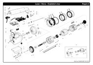
Spare parts - 56F510 ........................................................................................................................... 6-5<br />
Spare parts - 56F511 ........................................................................................................................... 6-6<br />
Spare parts - 56F514 ........................................................................................................................... 6-7<br />
7. DECLARATION OF CONFORMITY ......................................................................... 7-1<br />
HD X2 Ed. 0546
GENERAL INFORMATION<br />
1. GENERAL INFORMATION<br />
Description<br />
HD X2 is a Weft Feeder for heavy duty applications with yarn separation and<br />
mechanical sensors. It is normally used with very dusty yarns where optical sensors<br />
cannot be applied. It is basically recommended to weave polypropylene, but is also possible<br />
to weave other types of particularly thick yarns, where a high motor power is required.<br />
The following models are available:<br />
HD X2 with Funnel and Piezo input sensor (P/N 56F510)<br />
With anti balloon funnel (included).<br />
HD X2 with FLEX/BRUSH and Piezo input sensor (P/N 56F511)<br />
It can be fitted with bristle and Flex brakes (not included).<br />
HD X2 with Funnel and Piezo input sensor for roving (P/N 56F514)<br />
For applications with fiber glass roving.<br />
Characteristics<br />
<br />
<br />
<br />
<br />
<br />
<br />
<br />
<br />
The Weft Feeder can be set for S or Z winding directions depending on the yarn twist.<br />
Yarn separation adjustable up to 4,5 mm.<br />
Weft breakage control ("Loom Stop" function) through the TFE4 Weft Stop Motion<br />
piezo input sensor.<br />
Max speed can be selected through a four position switch.<br />
Overload and lock of the motor<br />
In both cases the motor stops and the relevant alarm is given by the signalling LED.<br />
Winding speed of the yarn on the Spool body<br />
The speed is automatically calculated and self adjusted according to the speed of the<br />
loom.<br />
Weft reserve<br />
The weft control is carried out by means of two mechanical sensors placed on the fi xed<br />
part of the Spool body.<br />
Preset for CAN communication<br />
1-1 - HD X2 Ed. 0546
Technical features<br />
GENERAL INFORMATION<br />
<br />
<br />
Power supply by means of a specific Roj control box .................... 290 V dc – 24 V dc<br />
Weft feeding speed: .........................................................min 60 - max 1.400 m/min<br />
(with CAN comunication): ............................................................... max 1.600 m/min<br />
Note:<br />
The maximum speed could be affected by causes not related to the HD X2.<br />
For instance:<br />
- At max separation on stand-alone configuration<br />
- Spooling not suitable<br />
- Weak weft<br />
- Etc.<br />
<br />
<br />
Threading channel: ....................................................................................8,5 x 6 mm<br />
Yarn count range: ...........................................................from Nm 0,5 up to 40* dtex<br />
(* 40 dtex is rated with input tensioner)<br />
Noise level: ...............................................................................................< 70 dB A<br />
Weight: .................................................................................................12,3 kg<br />
Working temperature: ..............................................................between 10° and 40°C<br />
Storage temperature: ...........................................................between –25° and 65°C<br />
Relative humidity: ..............................................................max 95% (not condensed)<br />
Further information<br />
<br />
The code (P/N) and the serial number (S/N), are printed on a label which is sticked on<br />
the left side of the Weft Feeder.<br />
Dimensions [mm]<br />
HD X2 - FUNNEL<br />
HD X2 - FLEX/BRUSH<br />
Fig. 1<br />
1-2 - HD X2 Ed. 0546
GENERAL INFORMATION<br />
HD X2 with Funnel and Piezo input sensor P/N 56F510 - Main Parts<br />
Signalling led<br />
Spool body<br />
On/Off switch<br />
Piezo input<br />
sensor<br />
Fixing tang<br />
Winding disc<br />
Sensor-holder ring<br />
fi g. 2<br />
Funnel<br />
1-3 - HD X2 Ed. 0546
GENERAL INFORMATION<br />
HD X2 with FLEX/BRUSH and Piezo input sensor P/N 56F511 - Main Parts<br />
On/Off switch<br />
Signalling led<br />
Spool body<br />
Brake adjustment<br />
knob<br />
Piezo input sensor<br />
Brake holder<br />
Fixing tang<br />
Winding disc<br />
Sensor-holder ring<br />
fi g. 3<br />
1-4 - HD X2 Ed. 0546
GENERAL INFORMATION<br />
HD X2/ROVING with FUNNEL and Piezo input sensor P/N 56F514 - Main Parts<br />
Signalling led<br />
Spool body<br />
On/Off switch<br />
Piezo input sensor<br />
Funnel<br />
Fixing tang<br />
Winding disc<br />
Sensor-holder ring<br />
fi g. 4<br />
1-5 - HD X2 Ed. 0546
CONTROL ELEMENTS<br />
2. CONTROL ELEMENTS<br />
Weft Feeder On/Off Switch<br />
Warning!<br />
The Weft Feeder On/Off switch, DOES NOT cut-off the main power supply (see fig. 5).<br />
fig. 5a<br />
Maximum Speed Switch<br />
To set the maximum speed rotate the switch to the appropriate position.<br />
500 m/min 800 m/min 1200 m/min 1600 m/min<br />
2-1 - HD X2 Ed. 0546<br />
fig. 5b<br />
Note:<br />
Normally the switch should be left to position 1600 m/min (fig.5b), since the feeder automatically<br />
calculates the speed according to yarn consumption. However, with very low speeds<br />
or wide looms, it could be helpful to reduce the maximum speed in order to avoid<br />
unnecessary acceleration.
VOLTAGE SUPPLY BOX<br />
3. VOLTAGE SUPPLY BOX<br />
The HD X2 feeder is compatible with the X2 stand-alone Voltage Supply Boxes.<br />
Note:<br />
For special applications, like multiple insertions of two or more yarns together, a Heavy Duty<br />
Voltage supply box, suitable for higher power consumption, is available (p/n 56C570).<br />
IMPORTANT!<br />
Please refer to the label sticked inside the Voltage Supply Box for the correct wiring according<br />
to the main power supply.<br />
• The interface board for the “Loom Stop” or “Automatic Package Switching”<br />
function, is integrated.<br />
3-1 - HD X2 Ed. 0546
INSTALLATION AND CONNECTION<br />
4. INSTALLATION AND CONNECTION<br />
Voltage Supply Box and Weft Feeder installation on the<br />
Stand<br />
1. Take the Voltage Supply Box out from the packing. Open the cover and connect the<br />
three-phase power cord (4-wires cable). Make sure that the earth connection is properly<br />
made (see fig. 6). The section of each wire cannot be less than 1.5 mm 2 .<br />
Warning!<br />
Such operation must be carried out BEFORE powering the unit.<br />
2. Fix the Voltage Supply Box to the Stand by means of the proper brackets<br />
(see fi g. 7 ).<br />
Note:<br />
Minimum distance from the Box to the floor must be 20 cm.<br />
3. Fix the Weft Feeders on the Stand by means of the existing clamps ensuring that the<br />
screws and locking nuts are correctly tightened.<br />
Notes:<br />
a. It is recommended to mount the Weft Feeders in horizontal position, in order to avoid<br />
coils falling into the funnel when the loom is stopped.<br />
b. Do not install the Weft Feeder directly on the loom structure: mechanical<br />
vibration may damage or interfere with the correct functioning of the unit.<br />
A complete line of Stands and Creels is available upon request to<br />
Nuova ROJ Electrotex Srl.<br />
c. Verify that the Weft Feeder Stand is electrically connected to ground.<br />
4. Place the Creel behind the Feeders' Stand avoiding sharp angles to the yarn path from<br />
the Creel output to the Feeders.<br />
> 20 cm<br />
fig. 6 fig. 7<br />
4-1 - HD X2 Ed. 0546
Electric connection<br />
INSTALLATION AND CONNECTION<br />
1. Connect the Feeders' cable to the Voltage Supply Box by following the numeric correspondence<br />
to the color selector's needles (Feeder working with the weft threaded in<br />
the needle 1 must be connected to the position 1 of the Voltage Supply Box; etc. see<br />
fi g.8).<br />
2. Connect the signal cable coming from the Voltage Supply Box to the Loom.<br />
3. Feeders' Stand and Creel must be connected to the earth of the Loom.<br />
4. Connect the plug of the 3-phase power cord to the socket available to the Loom panel.<br />
Voltage Supply Box (connections)<br />
Power supply network<br />
PE<br />
R<br />
S<br />
T<br />
Feeder 1<br />
Feeder 2<br />
Feeder 5<br />
Feeder 6<br />
Loom main switch<br />
Feeder 3<br />
Feeder 7<br />
Feeder 4<br />
Feeder 8<br />
Interface<br />
extension<br />
(12 color)<br />
Signal<br />
Cable<br />
(from<br />
loom)<br />
Weft Feeder<br />
Voltage Supply Box<br />
fig. 8<br />
4-2 - HD X2 Ed. 0546
INSTALLATION AND CONNECTION<br />
• Mains connection and Stop relay jumpers (see fig. 9 and fig. 10)<br />
fig. 9 fig. 10<br />
• Opto coupler signals and relay signal on the feeder connector of the Voltage<br />
Supply Box (see fig. 11)<br />
fig. 11<br />
• Fuses position on Power supply and on the communication interface<br />
(see fi g. 12 and fig. 13)<br />
fig. 12 fig. 13<br />
4-3 - HD X2 Ed. 0546
FUNCTIONING AND SETTING<br />
5. FUNCTIONING AND SETTING<br />
Manual threading<br />
1. Switch off the Weft Feeder.<br />
2. Insert the threader into the Weft Feeder entry hole and push it: the threader<br />
follows a guided path and comes out from the Winding disc eyelet.<br />
3. Hook the yarn to the threader slot (on the input side), and pull it (see fig. 14).<br />
4. Insert the Threader between the Spool body and the Sensor-holder ring up to the<br />
output of the funnel: in this way the Weft Feeder is fully threaded (see fig. 15).<br />
Important!<br />
Never pull the threader or the yarn backwards as it could damage the unit. In case of threading<br />
errors or if the yarn breaks, repeat the operation from the beginning.<br />
5. Switch On the Weft Feeder: the reserve is fully restored (the Signalling led will<br />
turn Off).<br />
fig.14<br />
fig.15<br />
5-1 - HD X2 Ed. 0546
FUNCTIONING AND SETTING<br />
Motor rotation direction and coil's pitch<br />
The motor rotation direction must be selected<br />
according to the yarn twist.<br />
Note<br />
In case of non-twisted yarns (flat yarn, monofilament,<br />
etc.), check the unwinding direction<br />
of the coil from the package and set the motor<br />
rotation to the opposite direction.<br />
Proceed as follows:<br />
fig.16<br />
1. Switch Off the Weft Feeder<br />
2. Set the direction of rotation (S or Z) with the switch (see fi g 19).<br />
3. Grip the winding disc and, whilst pressing the orange button on the front of the spool<br />
body, rotate the disc until the button is felt to locate.<br />
4. Keep the orange button pressed in and rotate the winding disc in the appropriate direction<br />
(the same as the rotation switch selection, see point 2). The Separation increases<br />
from 0 to 4 mm the more the disk is rotated (see fi g. 18).<br />
fig.18<br />
fig.17<br />
Z<br />
- 0 - S<br />
Note:<br />
The position "0" on the rotation switch (fig. 19)<br />
is used to disable the feeder when not used with<br />
the weft pattern.<br />
fig.19<br />
5-2 - HD X2 Ed. 0546
Mechanical sensors<br />
FUNCTIONING AND SETTING<br />
The weft control is carried out by two sensors (A and B) placed on the fixed part of the Spool<br />
body (see fig. 20).<br />
Note:<br />
If the Weft Feeder does not operate correctly without showing any alarm on the led, please<br />
follow the “Automatic setting of mechanical sensors” procedure.<br />
Automatic setting of mechanical sensors<br />
Before starting the operation, check the following:<br />
• The Spool body has not been turned (the sensors must be positioned as in<br />
picture 20).<br />
• The Sensors have not been damaged or blocked;<br />
• The Sensors-holder ring and the Spool body has equal distance in all directions to the<br />
Spool body.<br />
Then, proceed as follows:<br />
1. Switch the Weft Feeder OFF.<br />
2. Disable the TFE4 moving the switch to the DIS position (see fig. 21).<br />
3. Switch the Weft Feeder On and let it turn without weft until the winding disk stops. (Led<br />
= fi xed ON).<br />
4. Switch the Weft Feeder Off and enable the TFE4.<br />
At this point the feeder is ready for yarn threading.<br />
Sensor B<br />
Sensor A<br />
Enabling /<br />
disabling switch<br />
TFE4<br />
Front view<br />
fig. 20 fig. 21<br />
5-3 - HD X2 Ed. 0546
FUNCTIONING AND SETTING<br />
Funnel<br />
Suitable for heavy yarns which create large balloons. Suggested for polypropylene flat tape<br />
on projectile looms.<br />
Note:<br />
There is no braking function on the yarn when the funnel is installed since it is used only to<br />
control the balloon effect during the yarn taking-off.<br />
fig. 22<br />
Funnel fitting<br />
1. Slightly screw the 3 nuts (a) with the screws - (see fig. 23).<br />
2. Slide the fixing screws into the guides of the Sensor-holder ring.<br />
3. Push the funnel completely against the Sensor-holder ring.<br />
4. Position the screws in the proper slots, then fix them with the nuts (b).<br />
(a)<br />
(b)<br />
(a)<br />
(a)<br />
fig.23<br />
5-4 - HD X2 Ed. 0546
FUNCTIONING AND SETTING<br />
Flex Brake<br />
This brake is particularly suitable for rapier Looms which require a constant braking<br />
tension during the weft insertion. It is also suggested with jute and monofilament.<br />
It is not recommended when flat yarns are woven.<br />
Note<br />
Each brake is suitable for both yarn twist (S or Z).<br />
Flex brake ordering P/N<br />
DESCRIPTION<br />
Flex brake (medium)<br />
Flex brake (stiff)<br />
Flex brake (extra-stiff)<br />
P/N<br />
54F241<br />
54F242<br />
54F243<br />
fig.24<br />
Brush/Flex brake mounting<br />
1. Rotating the slide shift lever will detach the Brush<br />
/Flex holder from the spool body. (see fig. 24)<br />
2. Ensure that the Brush/Flex is correctly positioned.<br />
(see fi g. 25)<br />
3. Adjust the Balloon control / Brake tension.<br />
(see fi g. 26)<br />
fig.25<br />
Note:<br />
Excessive brush tension will cause abnormal wear.<br />
WARNING:<br />
When using a threading needle, care must be<br />
taken to avoid damaging the Flex Brake.<br />
Ensure that the flex holder is in the forward position<br />
before threading.<br />
Brush brake ordering P/N<br />
fig.26<br />
DESCRIPTION<br />
Brush brake (medium) - Z<br />
Brush brake (medium) - S<br />
Brush brake (stiff) - Z<br />
Brush brake (stiff) - S<br />
P/N<br />
54T801<br />
54T802<br />
54T803<br />
54T804<br />
fig.27<br />
Note:<br />
Check the mounting position of the nose:<br />
Flex = 30° Brush = 42° (see fig.27)<br />
30° 42°<br />
5-5 - HD X2 Ed. 0546
MAINTAINANCE AND TROUBLESHOOTING<br />
6. MAINTENANCE AND TROUBLESHOOTING<br />
Maintenance<br />
• It is recommended to periodically clean the lint or dust accumulated on the Weft Feeder<br />
and on the Voltage Supply Box, by using a low pressure compressed air jet.<br />
Note<br />
Before blowing the dust off, it is necessary to remove the yarn from the Spool body, in<br />
order to avoid that the air jet blows the weft inside the Winding disc.<br />
• The Weft feeder does not need extra lubrication.<br />
6-1 - HD X2 Ed. 0546
MAINTAINANCE AND TROUBLESHOOTING<br />
Troubleshooting<br />
Main problems and possible solutions are listed hereafter.<br />
The Weft Feeder gives an alarm signal by means of the front LED. The LED is flashing in<br />
case of problems, while it is Off during the normal operation.<br />
Failure / Cause<br />
Feeder will not start<br />
Incorrect S/Z switch position<br />
Incorrect spool body position<br />
Winding disc jammed<br />
Sensor arms jammed<br />
Faulty cable connections<br />
Fuses blown<br />
Mains supply / primary voltage fault<br />
Defective sensor board<br />
Defective motor board<br />
Defective fuse panel<br />
Sensor out of calibration<br />
Feeder will not stop<br />
Insuffi cient input tension<br />
Sensor arms jammed<br />
Defective sensor board<br />
Defective motor board<br />
Low or empty yarn store<br />
Insuffi cient max speed setting<br />
Winding disc jammed<br />
Sensor arms jammed<br />
Mains supply / primary voltage fault<br />
Defective sensor board<br />
Defective motor board<br />
Defective control box interface<br />
Defective fuse panel<br />
Input yarn breaks frequently<br />
Misalignment between the bobbin and the<br />
feeder<br />
Excessive input tension<br />
Excessive max speed setting<br />
Remedies<br />
Set the S/Z switch in appropriate position<br />
Ensure the sensor unit is positioned upwards<br />
Free and clean the winding disc<br />
Free the arms and clean the sensing unit<br />
Check and rectify<br />
Replace the relevant fuse<br />
Check the mains supply and connections<br />
Replace the sensor board (p/n 09E415R)<br />
Replace the motor board (p/n 09E442R)<br />
Replace the relevant fuse panel<br />
Execute automatic sensor calibration procedure<br />
(see page 5-3)<br />
Increase the input tension<br />
Free the arms and clean the sensing unit<br />
Replace the sensor board (p/n 09E415R)<br />
Replace the motor board (p/n 09E442R)<br />
Increase the max speed setting<br />
Free and clean the winding disc<br />
Free the arms and clean the sensing unit<br />
Check the mains supply and connections<br />
Replace the sensor board (p/n 09E415R)<br />
Replace the motor board (p/n 09E442R)<br />
Replace the interface board (located in the V.S.B.)<br />
Replace the relevant fuse panel<br />
Realign the bobbin/feeder<br />
Reduce the input tension<br />
Reduce the max speed setting<br />
6-2 - HD X2 Ed. 0546
MAINTAINANCE AND TROUBLESHOOTING<br />
Failure / Cause<br />
Output yarn breaks frequently<br />
Winding disc jammed<br />
Mains supply / primary voltage fault<br />
Defective motor board<br />
Defective fuse panel<br />
Defective control box interface<br />
Fuses blow repeatedly<br />
Defective motor board<br />
Feeder warning light flashes slowly<br />
Sensor out of calibration<br />
Feeder warning light flashes rapidly<br />
Winding disc jammed<br />
Mains supply / primary voltage fault<br />
Defective control box interface<br />
Defective motor board<br />
Defective fuse panel<br />
Remedies<br />
Free and clean the winding disc<br />
Check the mains supply and connections<br />
Replace the motor board (p/n 09E442R)<br />
Replace the relevant fuse panel<br />
Replace the interface board (located in the V.S.B.)<br />
Replace the motor board (p/n 09E442R)<br />
Execute automatic sensor calibration procedure<br />
(see page 5-3)<br />
Free and clean the winding disc<br />
Check the mains supply and connections<br />
Replace the interface board (located in the V.S.B.)<br />
Replace the motor board (p/n 09E442R)<br />
Replace the relevant fuse panel<br />
6-3 - HD X2 Ed. 0546
MAINTAINANCE AND TROUBLESHOOTING<br />
Electronic board replacement<br />
Attention!<br />
Before any operation, disconnect the Weft Feeder from the Voltage Supply Box.<br />
1. Unscrew the four screws and take off the top cover.<br />
2. Unscrew the shock hazard protection.<br />
3. Unplug the board electrical connections.<br />
4. Remove the electronic board (see fig. 28).<br />
fig.28<br />
5. The fi g. 29 shows the factory settings of the jumpers on the Electronic board,<br />
(this configuration must not be modified).<br />
J4 J3 J2 J1<br />
fig.29<br />
Note<br />
Whenever the electronic board or the sensors board are replaced, it is necessary to carry<br />
out the “Automatic sensor calibration procedure” (please refer to page 5-3).<br />
6-4 - HD X2 Ed. 0546
MAINTAINANCE AND TROUBLESHOOTING<br />
Spare parts - 56F510<br />
6-5 - HD X2 Ed. 0546
MAINTAINANCE AND TROUBLESHOOTING<br />
Spare parts - 56F511<br />
6-6 - HD X2 Ed. 0546
MAINTAINANCE AND TROUBLESHOOTING<br />
Spare parts - 56F514<br />
6-7 - HD X2 Ed. 0546
MAINTAINANCE AND TROUBLESHOOTING<br />
Spare parts - 56C570<br />
4024 control box - Exploded view<br />
21F3<br />
43A1109<br />
23A22<br />
21F55<br />
43A1110<br />
FUSE 5 A 250 V<br />
FUSE 3,15 A H 500 V<br />
05R931<br />
21F136<br />
34E273<br />
23A22<br />
8<br />
21P93<br />
43E78<br />
21F55<br />
12<br />
34E272<br />
(8) INTERFACE P/N<br />
09E296R INTERFACE PROMATECH<br />
09E421R INTERFACE SMIT<br />
09E297R INTERFACE STAND ALONE<br />
24.9136.0001 INTERFACE DORNIER<br />
24.9136.0002 INTERFACE SULTEX<br />
24.9136.0003 INTERFACE LOOMSIM<br />
24.9136.0004 INTERFACE AIR INDEX<br />
24.9136.0005 INTERFACE VAN DE WIELE<br />
(12) POWER CIRCUIT BOARD P/N<br />
09E377R<br />
09E376R<br />
09E375R<br />
POWER CIRCUIT BOARD LV<br />
POWER CIRCUIT BOARD MV<br />
POWER CIRCUIT BOARD HV<br />
28E849<br />
21F78<br />
15B53<br />
15B52<br />
ROJ Ref. No. 23E670-0545 GPer<br />
Ref. No. 24-891D-2001-01/0442<br />
6-8 - HD X2 Ed. 0546
7. DECLARATION OF CONFORMITY<br />
nuova Roj Electrotex s.r.l<br />
Via Vercellone, 11<br />
13900 BIELLA - ITALY<br />
DICHIARAZIONE CE DI CONFORMITA’<br />
EC DECLARATION OF CONFORMITY<br />
EG-KONFORMITÄTSERKLÄRUNG<br />
DECLARATION CE DE CONFORMITE<br />
DECLARACIÓN DE CONFORMIDAD CE<br />
DECLARAÇÃO CE DE CONFORMIDADE<br />
EG-FÖRSÄKRAN OM ÖVERENSSTÄMMELSE<br />
EC CONFORMITEIT<br />
Garantisce che il tipo di macchina:<br />
Guarantee that machine type:<br />
Versichert dass der Maschinentyp:<br />
Guarantie pour machine type:<br />
Garantiza que el tipo de màquina:<br />
Garantia de que os tipos de màquinas:<br />
Garanterar att maskintyp:<br />
Garandeert dat machine type:<br />
HD10 X2<br />
E’ costruito in conformità a quanto previsto dalle seguenti direttive UE e successive modifiche:<br />
Is manufactured in conformity with the provisions of the following EC directives and applicable amendments:<br />
Ist gemäss der folgenden für Maschinen geltenden EG-Richtlinien hergestellt worden (damit auch alle zusätzliche<br />
Änderungen):<br />
Est fabriqué en conformité aux dispositions des directives CE suivantes (y compris tous les amendements):<br />
Està fabricado conforme con las disposiciones de las debajo mencionadas directivas CE (y sucesivas<br />
modificaciones):<br />
Està fabricado em conformidade con o estabelecido nas seguintes directivas CE (incluindo alterações):<br />
Är tillverkad i överensstämmelse med villkoren i följande EG-direktiv och tillämpliga tillägg:<br />
Geproduceerd conform de EC regelmenteringen en toepasbare amandementen:<br />
Riferimento / Short name<br />
Sicurezza dei macchinari<br />
Safety of machinery<br />
Apparcchiature a bassa tensione<br />
Low voltage equipment<br />
Compatibilità elettromagnetica<br />
Electromagnetic compatibility<br />
98/37/EEC<br />
73/23/EEC 60204-1, 61310-2<br />
89/336/EEC<br />
Fiorenzo Ghiardo ‘97<br />
Managing Director<br />
7-1 - HD X2 Ed. 0546


