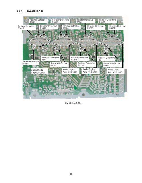
9.1.3. D-AMP P.C.B. Resistor Defective R5410 Resistor Defective R5405 Resistor Defective R5402 Resistor Defective R5005 Resistor Defective R5004 Resistor Defective R5201 Resistor Defective R5200 Resistor Defective R5305 Resistor Defective R5302 Resistor Defective R5411 Audio Digital Amp IC: IC5400 Resistor Defective R5011 Resistor Defective R5010 Audio Digital Amp IC: IC5000 Resistor Defective R5211 Resistor Defective R5210 Audio Digital Amp IC: IC5200 Resistor Defective R5311 Resistor Defective R5310 Audio Digital Amp IC: IC5300 Fig. 4 D-Amp P.C.B. 28
9.2. Troubleshooting Guide for F61 and/or F76 This section illustrates the checking procedures when upon detecting the error of “F61” and/or “F76” after power up of the unit. It is for purpose of troubleshooting and checking in SMPS, Main & D-Amp P.C.B.. Symptom Checking Items Possible Fault(s) Set cannot ON 1 AC Cord 1 AC Cord Faulty, Loose connection. 2 AC Inlet, P5701 2 P5701 solder crack, dry joint. 3 Fuse, F1 3 Fuse, F1 Open . 4 Photocoupler 4 PC5702/PC5799 solder crack. PC5702, PC5799 Dry joint, short circuit, open circuit. 5 Switching Regulator 5 IC5701 Faulty. IC, IC5701 6 Main Transformer T5751 6a 6b T5751 Faulty. Switching Mode Power Supply Control IC (IC5799) faulty. 6c D5798 faulty. Remarks Refer to Section 9.1.1 Fig. 1. SMPS P.C.B. Set can ON 1 Speaker Output 1 Faulty speaker unit, Loose connection, Short. then F61 2 D-AMP circuit 2a 2b D-AMP IC, IC5700, IC5800, IC5000, IC5200, IC5300, IC5400 defective. (Check DC voltage at speaker terminals, 3V and above defective) DC Voltage ok but no sound, check DC Voltage at Pin 1. 5V ok condition, 2.5V or 0V defective. 2c 2a, 2b ok but no sound, check PWM waveform at Pin 10 and Pin 14 . If no PWM, 24 resistors defective. For IC5700 (R5702, R5703, R5704, R5705). For IC5800 (R5802, R5803, R5804, R5805). For IC5000 (R5004, R5005, R5010, R5011). For IC5400 (R5402, R5405, R5410, R5411). For IC5200 (R5200, R5201, R5210, R5211). For IC5300 (R5302, R5305, R5310, R5311). Refer to Section 9.1.2 Fig. 3. Main P.C.B. and Section 9.1.3 Fig. 4. D-Amp P.C.B. Set can ON 1 Main Transformer T5701 1a Short circuit between Pin 11 and Pin 12 . then F76 1b Short circuit between Pin 13 and Pin 14 . 1c Short circuit between Pin 16 and Pin 17 . 2 Regulator Circuits 2a 2b 2c 2d 2e 2f IC2010 faulty (<strong>No</strong> +9V output). L2000 Open. Q2022 faulty (<strong>No</strong> +5V output). IC2014 faulty (<strong>No</strong> +3.3V output). IC2011 faulty (<strong>No</strong> +5V output). L2001 Open. Refer to Section 9.1.1 Fig. 1. SMPS P.C.B. Refer to Section 9.1.2 Fig. 2. and Fig.3. Main P.C.B. Set can ON working normally for some time then F76 3 Photocoupler 3 PC5720 solder crack, PC5720 Dry joint, short circuit, open circuit. 1 Rectifier Diode D5801 1a Improper contact between D5801 to Heatsink. Rectifier Diode D5802 Improper contact between D5802 to Heatsink. 2 Thermistor TH5860, 1b Set trigger temperature protection. TH5861 Refer to Section 9.1.1 Fig. 1. SMPS P.C.B. Refer to Section 9.1.1 Fig. 1. SMPS P.C.B. 29