- Page 1 and 2: PMX1208008CE CD Stereo System Model
- Page 3 and 4: 8.6. Sales Demonstration Lock Funct
- Page 5 and 6: 1.3. Before Repair and Adjustment D
- Page 7 and 8: 2 Warning 2.1. Prevention of Electr
- Page 9 and 10: 2.3. Service caution based on Legal
- Page 11 and 12: 2.4.2. Grounding for electrostatic
- Page 13 and 14: 4 Specifications Potencia de salida
- Page 15 and 16: 6 Location of Controls and Componen
- Page 17 and 18: 7 Installation Instructions 7.1. Sp
- Page 19 and 20: .2. Doctor Mode Table 8.2.1. Doctor
- Page 21 and 22: 8.2.3. Doctor Mode Table 3 Mode Nam
- Page 23 and 24: 8.4. Self-Diagnostic Mode Mode Name
- Page 25 and 26: 9 Troubleshooting Guide 9.1. Part L
- Page 27 and 28: Resistor Defective R5803 Resistor D
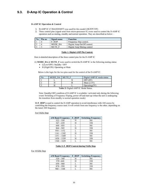
- Page 29: 9.2. Troubleshooting Guide for F61
- Page 33: 11 Disassembly and Assembly Instruc
- Page 36 and 37: 11.2. Main Components and P.C.B. Lo
- Page 38 and 39: 11.4. Disassembly of Front Panel Un
- Page 40 and 41: 11.6. Disassembly of Panel P.C.B.
- Page 42 and 43: 11.9. Disassembly of USB P.C.B. •
- Page 44 and 45: Step 3 Release 2 catches. Step 4 Re
- Page 46 and 47: Caution: During assembling, ensure
- Page 48 and 49: 11.15.2. Assembly of Voltage Regula
- Page 50 and 51: 11.17. Replacement of Audio Digital
- Page 52 and 53: Step 4 Slightly lift up & remove th
- Page 54 and 55: 11.20. Replacement of Audio Digital
- Page 56 and 57: 11.22. Replacement of Audio Digital
- Page 58 and 59: 11.24. Replacement of Switching Reg
- Page 60 and 61: Step 5 Solder pins of the Rectifier
- Page 62 and 63: 11.27. Replacement of Rectifier Dio
- Page 64 and 65: Step 3 Remove 1 screw at Rectifier
- Page 66 and 67: Step 5 Lift up and remove the SMPS
- Page 68 and 69: 11.32. Disassembly of Rear Panel R
- Page 70 and 71: 12.3. Checking and Repairing of Pan
- Page 72 and 73: 12.5. Checking and Repairing of CD
- Page 74 and 75: Step 3 Place the CD Servo P.C.B. on
- Page 76 and 77: 14 Block Diagram 14.1. Servo & Syst
- Page 78 and 79: 14.2. IC Terminal Chart TC IC8051 6
- Page 80 and 81:
: AUX/TUNER/MUSIC PORT/MIC AUDIO IN
- Page 82 and 83:
PW +16V TO POWER SUPPLY BLOCK (1/2)
- Page 84 and 85:
16 Schematic Diagram 16.1. Schemati
- Page 86 and 87:
15 16 17 18 19 20 21 22 23 24 25 26
- Page 88 and 89:
A CD SERVO CIRCUIT SCHEMATIC DIAGRA
- Page 90 and 91:
15 16 17 18 19 20 21 22 23 24 25 26
- Page 92 and 93:
43 44 45 46 47 48 49 50 51 52 53 54
- Page 94 and 95:
J K L M N O P B MAIN(MICON) CIRCUIT
- Page 96 and 97:
B MAIN(MICON) CIRCUIT SCHEMATIC DIA
- Page 98 and 99:
B MAIN(MICON) CIRCUIT SCHEMATIC DIA
- Page 100 and 101:
15 16 17 18 19 20 21 22 23 24 25 26
- Page 102 and 103:
15 16 17 18 19 20 21 22 23 24 25 26
- Page 104 and 105:
16.7. CD Interface, Mic 1 2 3 4 5 6
- Page 106 and 107:
15 16 17 18 19 20 21 22 23 24 25 26
- Page 108 and 109:
L D-AMP CIRCUIT SCHEMATIC DIAGRAM -
- Page 110 and 111:
15 16 17 18 19 20 21 22 23 24 25 26
- Page 112 and 113:
17.2. Main P.C.B. 1 1 2 3 4 5 6 7 8
- Page 114 and 115:
COMPONENTES DE PISTA MAIN PSG Ref.
- Page 116 and 117:
C2182 F1H1A474A025 Surface mounting
- Page 118 and 119:
CN2010 K1KA02BA0061 2-PIECE CONNECT
- Page 120 and 121:
R2019 ERJ3GEYJ683V Surface mounting
- Page 122 and 123:
R2227 ERJ3GEYJ473V SURFACE MOUNTING
- Page 124 and 125:
R5617 ERJ3GEYJ822V Surface mounting
- Page 126 and 127:
17.4. Memory LED, CD Interface, Top
- Page 128 and 129:
17.6. SMPS M SMPS P.C.B. (REPM12X95
- Page 130 and 131:
18.1.2. CD Servo P.C.B. (2/3) REF N
- Page 132 and 133:
18.1.5. Main P.C.B. (2/4) REF NO. I
- Page 134 and 135:
18.1.7. Main P.C.B. (4/4) REF NO. M
- Page 136 and 137:
18.1.10. SMPS P.C.B. REF NO. MODE 1
- Page 138 and 139:
18.2. Illustration of ICs, Transist
- Page 140 and 141:
19 Exploded View and Replacement Pa
- Page 142 and 143:
19.1.2. Packaging H SB-WAKX95 G SB-
- Page 144 and 145:
Safety Ref. No. Part No. Part Name
- Page 146 and 147:
Safety Ref. no. Part No. Part Name
- Page 148 and 149:
R5006 D0GZ220JA012 CHIP RESISTOR K5
- Page 150:
D6700 B3AEA0000172 LED D6701 B3AEA0