

Model No. SA-AKX95LMK - Panasonic
Model No. SA-AKX95LMK - Panasonic
Model No. SA-AKX95LMK - Panasonic

Create successful ePaper yourself
Turn your PDF publications into a flip-book with our unique Google optimized e-Paper software.
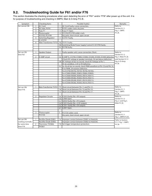
9.2. Troubleshooting Guide for F61 and/or F76<br />
This section illustrates the checking procedures when upon detecting the error of “F61” and/or “F76” after power up of the unit. It is<br />
for purpose of troubleshooting and checking in SMPS, Main & D-Amp P.C.B..<br />
Symptom<br />
Checking Items<br />
Possible Fault(s)<br />
Set cannot ON 1 AC Cord 1 AC Cord Faulty, Loose connection.<br />
2 AC Inlet, P5701<br />
2 P5701 solder crack, dry joint.<br />
3 Fuse, F1 3 Fuse, F1 Open .<br />
4 Photocoupler 4 PC5702/PC5799 solder crack.<br />
PC5702, PC5799<br />
Dry joint, short circuit, open circuit.<br />
5 Switching Regulator 5 IC5701 Faulty.<br />
IC, IC5701<br />
6 Main Transformer T5751 6a<br />
6b<br />
T5751 Faulty.<br />
Switching Mode Power Supply Control IC (IC5799) faulty.<br />
6c D5798 faulty.<br />
Remarks<br />
Refer to<br />
Section 9.1.1<br />
Fig. 1. SMPS<br />
P.C.B.<br />
Set can ON 1 Speaker Output 1 Faulty speaker unit, Loose connection, Short.<br />
then F61<br />
2 D-AMP circuit 2a<br />
2b<br />
D-AMP IC, IC5700, IC5800, IC5000, IC5200, IC5300, IC5400 defective.<br />
(Check DC voltage at speaker terminals, 3V and above defective)<br />
DC Voltage ok but no sound, check DC Voltage at Pin 1.<br />
5V ok condition, 2.5V or 0V defective.<br />
2c 2a, 2b ok but no sound, check PWM waveform at Pin 10 and Pin 14 .<br />
If no PWM, 24 resistors defective.<br />
For IC5700 (R5702, R5703, R5704, R5705).<br />
For IC5800 (R5802, R5803, R5804, R5805).<br />
For IC5000 (R5004, R5005, R5010, R5011).<br />
For IC5400 (R5402, R5405, R5410, R5411).<br />
For IC5200 (R5200, R5201, R5210, R5211).<br />
For IC5300 (R5302, R5305, R5310, R5311).<br />
Refer to<br />
Section 9.1.2<br />
Fig. 3. Main P.C.B.<br />
and Section 9.1.3<br />
Fig. 4. D-Amp<br />
P.C.B.<br />
Set can ON 1 Main Transformer T5701 1a Short circuit between Pin 11 and Pin 12 .<br />
then F76 1b Short circuit between Pin 13 and Pin 14 .<br />
1c Short circuit between Pin 16 and Pin 17 .<br />
2<br />
Regulator Circuits<br />
2a<br />
2b<br />
2c<br />
2d<br />
2e<br />
2f<br />
IC2010 faulty (<strong>No</strong> +9V output).<br />
L2000 Open.<br />
Q2022 faulty (<strong>No</strong> +5V output).<br />
IC2014 faulty (<strong>No</strong> +3.3V output).<br />
IC2011 faulty (<strong>No</strong> +5V output).<br />
L2001 Open.<br />
Refer to<br />
Section 9.1.1<br />
Fig. 1. SMPS<br />
P.C.B.<br />
Refer to<br />
Section 9.1.2<br />
Fig. 2. and Fig.3.<br />
Main P.C.B.<br />
Set can ON<br />
working normally<br />
for some time<br />
then F76<br />
3 Photocoupler 3 PC5720 solder crack,<br />
PC5720<br />
Dry joint, short circuit, open circuit.<br />
1 Rectifier Diode D5801 1a Improper contact between D5801 to Heatsink.<br />
Rectifier Diode D5802 Improper contact between D5802 to Heatsink.<br />
2 Thermistor TH5860, 1b Set trigger temperature protection.<br />
TH5861<br />
Refer to<br />
Section 9.1.1<br />
Fig. 1. SMPS P.C.B.<br />
Refer to Section<br />
9.1.1 Fig. 1. SMPS<br />
P.C.B.<br />
29


