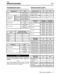
DTC P0107, P0108 5.19 - harley-davidson-sweden.se
DTC P0107, P0108 5.19 - harley-davidson-sweden.se
DTC P0107, P0108 5.19 - harley-davidson-sweden.se

Create successful ePaper yourself
Turn your PDF publications into a flip-book with our unique Google optimized e-Paper software.
HOME<br />
<strong>DTC</strong> P1351, P1352, P1354, P1355 5.29<br />
GENERAL<br />
7863<br />
Ignition Coil<br />
Ignition coil codes will <strong>se</strong>t if the ignition coil primary voltage is<br />
out of range. This could occur if there is an open coil or loss of<br />
power to the coil. If front and rear codes are <strong>se</strong>t simultaneously,<br />
it is likely a coil power failure or a coil failure.<br />
The coil receives power from the system relay at the same<br />
time that the fuel pump and injectors are activated. The system<br />
relay is active for the first 2 <strong>se</strong>conds after the ignition is<br />
turned ON and then shuts off until RPM is detected from the<br />
CKP <strong>se</strong>nsor, at which time it is reactivated. The ECM is<br />
responsible for turning on the system relay by providing the<br />
ground to activate the relay, which in turn powers the coil.<br />
Table 5-50. Code Description<br />
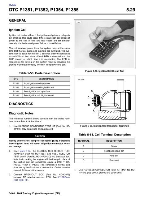
Figure 5-67. Ignition Coil Circuit Test<br />
<strong>DTC</strong><br />
P1351<br />
P1352<br />
P1354<br />
P1355<br />
DESCRIPTION<br />
Front ignition coil open/low<br />
Front ignition coil high/shorted<br />
Rear ignition coil open/low<br />
Rear ignition coil high/shorted<br />
s0475x9x<br />
C<br />
D<br />
DIAGNOSTICS<br />
B<br />
Diagnostic Notes<br />
A<br />
The reference numbers below correlate with the circled numbers<br />
on the Test 5.29 flow charts.<br />
1. U<strong>se</strong> HARNESS CONNECTOR TEST KIT (Part No. HD-<br />
41404), gray pin probes and patch cord.<br />
CAUTION<br />
Figure 5-68. Ignition Coil Connector Terminals<br />
Table 5-51. Coil Terminal Description<br />
Gently connect test lamp to connector [83B]. Forcefully<br />
in<strong>se</strong>rting test lamp will result in ignition connector terminal<br />
damage.<br />
TERMINAL<br />
A<br />
DESCRIPTION<br />
Power<br />
2. See Figure 5-67. Plug IGNITION COIL CIRCUIT TEST<br />
ADAPTER (Part No. HD-44687) and FUEL INJECTOR<br />
TEST LAMP (Part No. HD-34730-2C) into Breakout Box.<br />
Note that cranking the engine with test lamp in place of<br />
the ignition coil can sometimes cau<strong>se</strong> a <strong>DTC</strong> P1351,<br />
P1352, P1354 or P1355. This condition is normal and<br />
does not by it<strong>se</strong>lf indicate a malfunction. Codes must be<br />
cleared if this condition occurs.<br />
3. Connect BREAKOUT BOX (Part No. HD-43876)<br />
between EFI wire harness and ECM. See 5.7 BREAK-<br />
OUT BOX: EFI.<br />
B<br />
C<br />
D<br />
Feedback signal pin<br />
Rear coil<br />
Front coil<br />
4. U<strong>se</strong> HARNESS CONNECTOR TEST KIT (Part No. HD-<br />
41404), gray socket probes and patch cord.<br />
5-108 2004 Touring: Engine Management (EFI)