DTC P0107, P0108 5.19 - harley-davidson-sweden.se
DTC P0107, P0108 5.19 - harley-davidson-sweden.se
DTC P0107, P0108 5.19 - harley-davidson-sweden.se

You also want an ePaper? Increase the reach of your titles
YUMPU automatically turns print PDFs into web optimized ePapers that Google loves.
7<br />
HOME<br />
<strong>DTC</strong> <strong>P0107</strong>, <strong>P0108</strong> <strong>5.19</strong><br />
GENERAL<br />
f1939x9x<br />
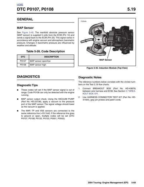
MAP Sensor<br />
See Figure 5-45. The manifold absolute pressure <strong>se</strong>nsor<br />
(MAP <strong>se</strong>nsor) is supplied 5 volts from the ECM (Pin 14) and<br />
<strong>se</strong>nds a signal back to the ECM (Pin 25). This signal varies in<br />
accordance with engine vacuum and atmospheric barometric<br />
pressure. Changes in barometric pressure are influenced by<br />
weather and altitude.<br />
Table 5-26. Code Description<br />
<strong>DTC</strong><br />
<strong>P0107</strong><br />
<strong>P0108</strong><br />
MAP <strong>se</strong>nsor open/low<br />
MAP <strong>se</strong>nsor high<br />
DESCRIPTION<br />
MAP Sensor<br />
Figure 5-45. Induction Module (Top View)<br />
DIAGNOSTICS<br />
Diagnostic Tips<br />
●<br />
●<br />
●<br />
The<strong>se</strong> codes will <strong>se</strong>t if the MAP <strong>se</strong>nsor signal is out of<br />
range. Code <strong>P0108</strong> can only be detected with the engine<br />
running.<br />
MAP <strong>se</strong>nsor output check. Using the VACUUM PUMP<br />
(Part No. HD-23738), apply a vacuum to the pressure<br />
port of the MAP <strong>se</strong>nsor. The signal voltage should lower<br />
as the vacuum is applied.<br />
The MAP, TP and VSS <strong>se</strong>nsors are connected to the<br />
same reference line (+5V Vref). If the reference line goes<br />
to ground or open, multiple codes will be <strong>se</strong>t (<strong>DTC</strong><br />
<strong>P0107</strong>, <strong>P0108</strong>, P0122, P0123, P0501, P0502).<br />
Diagnostic Notes<br />
The reference numbers below correlate with the circled numbers<br />
on the Test <strong>5.19</strong> flow charts.<br />
1. Connect BREAKOUT BOX (Part No. HD-43876)<br />
between wire harness and ECM. See Section 5.7 BREA-<br />
KOUT BOX: EFI.<br />
2. U<strong>se</strong> HARNESS CONNECTOR TEST KIT (Part No. HD-<br />
41404), gray pin probes and patch cords.<br />
2004 Touring: Engine Management (EFI) 5-69
HOME<br />
f1743q9s<br />
MAP<br />
Sensor<br />
[80A]<br />
A B C<br />
[80B]<br />
A<br />
B<br />
C<br />
BK/W<br />
V/W<br />
R/W<br />
To TP, ET &<br />
IAT Sensors<br />
To TP and<br />
VSS <strong>se</strong>nsors<br />
V/W<br />
R/W<br />
BK/W<br />
[78B]<br />
[78A]<br />
ECM<br />
14 25 26<br />
Figure 5-46. MAP Sensor Circuit<br />
Table 5-27. Wire Harness Connectors in Figure 5-46.<br />
NO. DESCRIPTION TYPE LOCATION<br />
[78] ECM 36-Place Packard Under Right Side Cover<br />
[80] MAP Sensor 3-Place Packard Top of Induction Module<br />
5-70 2004 Touring: Engine Management (EFI)
HOME<br />
Test <strong>5.19</strong> (Part 1 of 2)<br />
MAP SENSOR: <strong>DTC</strong> <strong>P0107</strong>, <strong>P0108</strong><br />
1<br />
Connect Breakout Box. With ignition ON,<br />
measure voltage between terminal 25<br />
and terminal 26 on Breakout Box.<br />
With key ON, engine OFF, voltage must be<br />
between 3.5 and 5.0 volts.<br />
With key ON, engine running, voltage must<br />
be between 1.5-3.0 volts at hot idle.<br />
Does voltage fit specifications<br />
YES<br />
NO<br />
Perform 5.8 WIGGLE TEST<br />
to check for intermittents.<br />
Intermittents pre<strong>se</strong>nt<br />
STOP<br />
Go to Test <strong>5.19</strong> (Part 2 of 2).<br />
YES<br />
NO<br />
To identify the source of intermittents,<br />
start with box marked by Bold Asterisk<br />
under Test <strong>5.19</strong> (Part 2 of 2). Wiggle<br />
harness while watching DVOM.<br />
Replace MAP <strong>se</strong>nsor. Clear codes and road<br />
test. Did check engine lamp illuminate and<br />
<strong>se</strong>t <strong>DTC</strong> <strong>P0107</strong> or <strong>P0108</strong><br />
YES<br />
NO<br />
Install original MAP <strong>se</strong>nsor.<br />
Replace ECM (reprogram,<br />
relearn) and road test again<br />
to verify.<br />
System<br />
now OK.<br />
At some point in the flow chart you<br />
may be instructed to jump directly<br />
to a the box with the bold asterisk.<br />
Disregard the asterisk (but not the<br />
instruction box) if your normal progression<br />
through the chart brings<br />
you to this location.<br />
Clear codes using speedometer <strong>se</strong>lf diagnostics.<br />
See 5.6 SPEEDOMETER SELF DIAGNOSTICS.<br />
Confirm proper operation with no check engine<br />
lamp.<br />
2004 Touring: Engine Management (EFI) 5-71
HOME<br />
Test <strong>5.19</strong> (Part 2 of 2)<br />
MAP SENSOR: <strong>DTC</strong> <strong>P0107</strong>, <strong>P0108</strong><br />
Continued from<br />
Test <strong>5.19</strong> (Part 1 of 2).<br />
2<br />
Check the 5 volt reference supply at<br />
the MAP <strong>se</strong>nsor connector [80B]. With<br />
ignition ON, measure voltage between<br />
terminal C (R/W) and terminal A (BK/W).<br />
Voltage approximately 5.0 volts<br />
YES<br />
NO.<br />
Greater<br />
than 6V.<br />
NO.<br />
Less<br />
than 4.5V.<br />
2<br />
Connect Breakout Box to connector [78B]<br />
leaving ECM disconnected.<br />
OPEN CHECK: Measure resistance<br />
between MAP connector [80B]<br />
Terminal B and Breakout Box terminal 25.<br />
Resistance less than 1 ohm<br />
Locate short to 12 volts on R/W<br />
wire in wire harness. Repair as<br />
necessary.<br />
2<br />
Connect Breakout Box to connector [78B]<br />
leaving ECM disconnected.<br />
Check continuity between MAP connector<br />
[80B] Terminal C and Breakout Box<br />
terminal 14. Then measure continuity<br />
between MAP connector [80B] Terminal A<br />
and Breakout Box terminal 26.<br />
Resistance less than 1 ohm<br />
YES<br />
NO<br />
2<br />
SHORT CHECK: Measure<br />
resistance between MAP connector<br />
Terminal B and chassis<br />
ground. Resistance greater<br />
than 1 megohm<br />
Locate and repair<br />
open on V/W wire.<br />
YES<br />
NO<br />
YES<br />
NO<br />
Check resistance between<br />
MAP connector [80B]<br />
Terminal C and<br />
Breakout Box terminal 26.<br />
Resistance greater than<br />
1 megohm<br />
Repair<br />
open wire.<br />
Replace MAP <strong>se</strong>nsor. See<br />
Touring Service Manual.<br />
Locate and repair<br />
grounded V/W wire.<br />
YES<br />
NO<br />
Replace ECM.<br />
Reprogram and learn<br />
password.<br />
Locate and repair<br />
short between<br />
R/W and BK/W<br />
wires.<br />
Clear codes using speedometer <strong>se</strong>lf diagnostics.<br />
See 5.6 SPEEDOMETER SELF DIAGNOSTICS.<br />
Confirm proper operation with no check engine<br />
lamp.<br />
At some point in the flow chart you<br />
may be instructed to jump directly<br />
to a the box with the bold asterisk.<br />
Disregard the asterisk (but not the<br />
instruction box) if your normal progression<br />
through the chart brings<br />
you to this location.<br />
5-72 2004 Touring: Engine Management (EFI)
HOME<br />
<strong>DTC</strong> P0112, P0113 5.20<br />
GENERAL<br />
DIAGNOSTICS<br />
IAT Sensor<br />
The ECM supplies and monitors a voltage signal (terminal 7)<br />
to one side of the intake air temperature <strong>se</strong>nsor (IAT <strong>se</strong>nsor).<br />
The other side of the IAT <strong>se</strong>nsor is connected to a common<br />
<strong>se</strong>nsor ground, which is also connected to the ECM (terminal<br />
26).<br />
The IAT <strong>se</strong>nsor is a thermistor device, meaning that at a specific<br />
temperature, it will have a specific resistance across its<br />
terminals. As this resistance varies, so does the voltage on<br />
(terminal 7).<br />
●<br />
At high temperatures, the resistance of the <strong>se</strong>nsor is very<br />
low, which effectively lowers the signal voltage on terminal<br />
7.<br />
● At low temperatures, the resistance is very high, allowing<br />
the voltage to ri<strong>se</strong> clo<strong>se</strong> to 5 volts.<br />
The ECM monitors this voltage to compensate for various<br />
operating conditions.<br />
<strong>DTC</strong><br />
P0112<br />
P0113<br />
Table 5-28. Code Description<br />
DESCRIPTION<br />
IAT <strong>se</strong>nsor voltage low<br />
IAT <strong>se</strong>nsor open/high<br />
Table 5-29. IAT Sensor Table<br />
TEMP °C RESISTANCE VOLTAGE TEMP °F<br />
-20 29121 4.9 -4<br />
-10 16599 4.8 14<br />
0 9750 4.6 32<br />
10 5970 4.3 50<br />
20 3747 4.0 68<br />
25 3000 3.8 77<br />
30 2417 3.6 86<br />
40 1598 3.1 104<br />
50 1080 2.6 122<br />
60 746 2.2 140<br />
70 526 1.7 158<br />
80 377 1.4 176<br />
90 275 1.1 194<br />
100 204 0.9 212<br />
Diagnostic Tips<br />
An intermittent may be cau<strong>se</strong>d by a poor connection, rubbed<br />
through wire insulation or a wire broken inside the insulation.<br />
Check the following conditions:<br />
●<br />
●<br />
●<br />
Poor connection: Inspect ECM and harness connector<br />
[78] for backed out terminals, improper mating, broken<br />
locks, improperly formed or damaged terminals, poor terminal-to-wire<br />
connection and damaged harness.<br />
Perform 5.8 WIGGLE TEST to locate intermittents: If<br />
connections and harness check out OK, u<strong>se</strong> a DVOM to<br />
check the intake air temperature <strong>se</strong>nsor voltage reading<br />
while moving related connectors and wiring harness. If<br />
the failure is induced, the intake air temperature <strong>se</strong>nsor<br />
voltage reading will change.<br />
Shifted <strong>se</strong>nsor: Refer to Table 5-29. This table may be<br />
u<strong>se</strong>d to test the intake air temperature <strong>se</strong>nsor at various<br />
temperature levels in order to evaluate the possibility of a<br />
shifted (out-of-calibration) <strong>se</strong>nsor which may result in<br />
driveability problems.<br />
NOTE<br />
All voltage and resistance values are approximate (±20%).<br />
Measure IAT <strong>se</strong>nsor resistance between ECM Terminal 7 and<br />
system ground (ECM Terminal 26).<br />
Diagnostic Notes<br />
The reference numbers below correlate with the circled numbers<br />
on the Test 5.20 flow charts.<br />
1. Connect BREAKOUT BOX (Part No. HD-43876) to EFI<br />
wire harness only (leave ECM disconnected). See 5.7<br />
BREAKOUT BOX: EFI.<br />
2. U<strong>se</strong> HARNESS CONNECTOR TEST KIT (Part No. HD-<br />
41404), gray pin probes and patch cords.<br />
3. U<strong>se</strong> HARNESS CONNECTOR TEST KIT (Part No. HD-<br />
41404), gray socket probes and patch cords.<br />
4. Replace IAT <strong>se</strong>nsor. See Touring Service Manual.<br />
2004 Touring: Engine Management (EFI) 5-73
HOME<br />
f1743r9s<br />
IAT<br />
Sensor<br />
[89A]<br />
A B<br />
[89B]<br />
A<br />
B<br />
Lt GN/Y<br />
BK/W<br />
To TP, ET &<br />
MAP Sensors<br />
Lt GN/Y<br />
BK/W<br />
[78B]<br />
[78A]<br />
ECM<br />
7 26<br />
Figure 5-47. IAT Sensor Circuit<br />
Table 5-30. Wire Harness Connectors in Figure 5-47.<br />
NO. DESCRIPTION TYPE LOCATION<br />
[78] ECM 36-Place Packard Under Right Side Cover<br />
[89] IAT Sensor 2-Place Packard Below Fuel Tank (Right Side)<br />
5-74 2004 Touring: Engine Management (EFI)
HOME<br />
Test 5.20 (Part 1 of 2)<br />
IAT SENSOR: <strong>DTC</strong> P0112, P0113<br />
1<br />
Connect Breakout Box to connector [78B] leaving<br />
ECM disconnected. With engine at room temperature<br />
(60-90° F or 16-32° C), u<strong>se</strong> a DVOM to measure<br />
resistance across terminals 7 and 26 on Breakout<br />
Box. If engine is warm, refer to Table 5-29.<br />
Resistance between 2.0k ohms and 5.0k ohms at<br />
room temperature<br />
YES<br />
NO<br />
Connect ECM to Breakout Box.<br />
Perform 5.8 WIGGLE TEST to check for<br />
intermittents. Intermittents pre<strong>se</strong>nt<br />
STOP<br />
Go to Test 5.20 (Part 2 of 2).<br />
YES<br />
NO<br />
While wiggling harness, perform<br />
steps marked by BOLD ASTER-<br />
ISKS under Test 5.20 (Part 2 of 2).<br />
Repair as necessary.<br />
Disconnect IAT <strong>se</strong>nsor connector [89].<br />
Turn ignition ON. Using a DVOM, measure<br />
the voltage<br />
between ECM terminal 7 (positive) and<br />
terminal 26 (negative) on Breakout Box.<br />
Voltage approximately 5 volts<br />
YES<br />
NO.<br />
Less than<br />
4.7 volts.<br />
NO.<br />
Greater than<br />
5.3 volts.<br />
Replace IAT <strong>se</strong>nsor, clear codes and<br />
road test. Did check engine lamp illuminate<br />
and <strong>se</strong>t <strong>DTC</strong> P0112 or<br />
P0113<br />
1<br />
With IAT <strong>se</strong>nsor disconnected,<br />
disconnect ECM from breakout box.<br />
Measure resistance between<br />
Breakout Box terminal 7 and terminals<br />
10 or 28.<br />
Resistance less than 1 megohm<br />
1<br />
Unplug ECM leaving Breakout Box connected<br />
at vehicle harness.<br />
Measure voltage between<br />
Breakout Box terminal 7 and terminals 10<br />
or 28.<br />
Voltage 0 volts<br />
YES<br />
NO<br />
YES<br />
NO<br />
YES<br />
NO<br />
Install original IAT<br />
<strong>se</strong>nsor, replace ECM,<br />
perform password<br />
learning and road test.<br />
System<br />
OK.<br />
Repair short to<br />
ground on<br />
Lt GN/Y wire.<br />
Replace ECM.<br />
Reprogram and<br />
learn password.<br />
Replace ECM.<br />
Reprogram and<br />
learn password.<br />
Examine IAT signal<br />
wire (Lt GN/Y)<br />
for short to voltage<br />
and repair.<br />
Clear codes using speedometer <strong>se</strong>lf diagnostics.<br />
See 5.6 SPEEDOMETER SELF DIAGNOSTICS.<br />
Confirm proper operation with no check engine<br />
lamp.<br />
At some point in the flow chart you<br />
may be instructed to jump directly<br />
to a the box with the bold asterisk.<br />
Disregard the asterisk (but not the<br />
instruction box) if your normal progression<br />
through the chart brings<br />
you to this location.<br />
2004 Touring: Engine Management (EFI) 5-75
HOME<br />
Test 5.20 (Part 2 of 2)<br />
IAT SENSOR: <strong>DTC</strong> P0112, P0113<br />
Continued from<br />
Test 5.20 (Part 1 of 2).<br />
Disconnect IAT <strong>se</strong>nsor connector [89B] and<br />
examine for damage. Connector OK<br />
YES<br />
NO<br />
2<br />
Using a DVOM, measure the resistance<br />
between IAT <strong>se</strong>nsor connector [89B]<br />
Terminal A and ECM terminal 7 on Breakout<br />
Box. Resistance less than 1.0 ohm<br />
Repair<br />
connector.<br />
YES<br />
NO<br />
2<br />
Using a DVOM, measure the resistance<br />
between IAT <strong>se</strong>nsor connector [89B]<br />
Terminal B and ECM terminal 26 on Breakout<br />
Box. Resistance less than 1.0 ohm<br />
Examine Lt GN/Y wire in<br />
harness for open circuit<br />
and repair.<br />
YES<br />
NO<br />
Using a DVOM, measure the resistance<br />
between ECM terminal 7 and terminal 26 on<br />
Breakout Box. Resistance greater<br />
than 1.0 megohm<br />
Examine BK/W wire in<br />
harness for open circuit<br />
and repair.<br />
YES<br />
NO<br />
Using a DVOM, measure the resistance<br />
between ECM terminal 7 on Breakout Box<br />
and ground. Resistance greater<br />
than 1.0 megohm<br />
Examine Lt GN/Y and<br />
BK/W wires in harness<br />
for short between the<strong>se</strong><br />
two circuits and repair.<br />
YES<br />
NO<br />
3<br />
Remove IAT <strong>se</strong>nsor and measure resistance<br />
across the terminals of the IAT <strong>se</strong>nsor<br />
directly. Again, with <strong>se</strong>nsor at room temperature<br />
60-90° F or 16-32° C), is resistance<br />
between 2.0k ohms and 5.0k ohms<br />
Examine harness for<br />
short to ground and<br />
repair.<br />
YES<br />
Perform 5.8 WIGGLE TEST on steps<br />
marked with a BOLD ASTERISK above to<br />
locate intermittents. Repair as necessary.<br />
4<br />
NO<br />
Replace<br />
IAT <strong>se</strong>nsor.<br />
At some point in the flow chart you<br />
may be instructed to jump directly<br />
to a the box with the bold asterisk.<br />
Disregard the asterisk (but not the<br />
instruction box) if your normal progression<br />
through the chart brings<br />
you to this location.<br />
Clear codes using speedometer <strong>se</strong>lf diagnostics.<br />
See 5.6 SPEEDOMETER SELF DIAGNOSTICS.<br />
Confirm proper operation with no check engine<br />
lamp.<br />
5-76 2004 Touring: Engine Management (EFI)
HOME<br />
<strong>DTC</strong> P0117, P0118 5.21<br />
GENERAL<br />
ET Sensor<br />
The ECM supplies and monitors a voltage signal (terminal 6)<br />
to one side of the engine temperature <strong>se</strong>nsor (ET <strong>se</strong>nsor).<br />
The other side of the ET <strong>se</strong>nsor is connected to a common<br />
<strong>se</strong>nsor ground (terminal 26) of the ECM.<br />
The ET <strong>se</strong>nsor is a thermistor device, which means that at a<br />
specific temperature it will have a specific resistance across<br />
its terminals. As this resistance varies, so does the voltage<br />
(terminal 6).<br />
●<br />
At high temperatures, the resistance of the <strong>se</strong>nsor is very<br />
low, which effectively lowers the signal voltage on terminal<br />
6.<br />
● At low temperatures, the resistance is very high, allowing<br />
the voltage to ri<strong>se</strong> clo<strong>se</strong> to 5 volts.<br />
The ECM monitors this voltage to compensate for various<br />
operating conditions. The ECM also u<strong>se</strong>s the <strong>se</strong>nsor input as<br />
a reference for determining IAC pintle position.<br />
<strong>DTC</strong><br />
P0117<br />
P0118<br />
Table 5-31. Code Description<br />
DESCRIPTION<br />
ET <strong>se</strong>nsor voltage low<br />
ET <strong>se</strong>nsor open/high<br />
Table 5-32. ET Sensor Table<br />
TEMP °C RESISTANCE VOLTAGE TEMP °F<br />
-20 28144 4.4 -4<br />
-10 15873 4.0 14<br />
0 9255 3.5 32<br />
10 5571 3.0 50<br />
20 3457 2.4 68<br />
25 2750 2.1 77<br />
30 2205 1.8 86<br />
40 1442 1.3 or 4.1* 104<br />
50 965 1.0 or 3.7* 122<br />
60 661 3.3 140<br />
70 462 2.9 158<br />
80 329 2.5 176<br />
90 238 2.1 194<br />
100 175 1.7 212<br />
DIAGNOSTICS<br />
Diagnostic Tips<br />
●<br />
●<br />
Once the engine is started, the ET voltage should ri<strong>se</strong><br />
steadily.<br />
An intermittent may be cau<strong>se</strong>d by a poor connection,<br />
rubbed through wire insulation or a wire broken inside<br />
the insulation.<br />
Check the following conditions:<br />
●<br />
●<br />
●<br />
Poor connection: Inspect ECM and harness connector<br />
[78] for backed out terminals, improper mating, broken<br />
locks, improperly formed or damaged terminals, poor terminal-to-wire<br />
connection and damaged harness.<br />
Perform 5.8 WIGGLE TEST to locate intermittents: If<br />
connections and harness check out OK, u<strong>se</strong> a DVOM to<br />
check the engine temperature <strong>se</strong>nsor voltage reading<br />
while moving related connectors and wiring harness. If<br />
the failure is induced, the engine temperature <strong>se</strong>nsor<br />
voltage reading will change.<br />
Shifted <strong>se</strong>nsor: Refer to Table 5-32. This table may be<br />
u<strong>se</strong>d to test the engine temperature <strong>se</strong>nsor at various<br />
temperature levels in order to evaluate the possibility of a<br />
shifted (out-of-calibration) <strong>se</strong>nsor which may result in<br />
driveability problems.<br />
NOTE<br />
All voltage and resistance values are approximate (±20%).<br />
Measure ET <strong>se</strong>nsor resistance between ECM Terminal 6 and<br />
system ground (ECM Terminal 26).<br />
Diagnostic Notes<br />
The reference numbers below correlate with the circled numbers<br />
on the Test 5.21 flow charts.<br />
1. Connect BREAKOUT BOX (Part No. HD-43876) to EFI<br />
wire harness only (leave ECM disconnected). See 5.7<br />
BREAKOUT BOX: EFI.<br />
2. U<strong>se</strong> HARNESS CONNECTOR TEST KIT (Part No. HD-<br />
41404), gray pin probes and patch cords.<br />
3. U<strong>se</strong> HARNESS CONNECTOR TEST KIT (Part No. HD-<br />
41404), gray socket probes and patch cords.<br />
4. Replace ET <strong>se</strong>nsor. See Touring Service Manual.<br />
* Between 40-50°C the ECM changes scaling. Voltages for ECT<br />
<strong>se</strong>nsor will shift scales in that range. This provides proper <strong>se</strong>nsor resolution<br />
for all temperatures.<br />
2004 Touring: Engine Management (EFI) 5-77
HOME<br />
f1743s9s<br />
ET<br />
Sensor<br />
[90A]<br />
[90B]<br />
A<br />
A<br />
B<br />
B<br />
PK/Y<br />
BK/W<br />
To TP, IAT &<br />
MAP Sensors<br />
PK/Y<br />
BK/W<br />
[78B]<br />
[78A]<br />
ECM<br />
6 26<br />
Figure 5-48. ET Sensor Circuit<br />
Table 5-33. Wire Harness Connectors in Figure 5-48.<br />
NO. DESCRIPTION TYPE LOCATION<br />
[78] ECM 36-Place Packard Under Right Side Cover<br />
[90] ET Sensor 2-Place Packard Back of Front Cylinder (Left Side)<br />
5-78 2004 Touring: Engine Management (EFI)
HOME<br />
Test 5.21 (Part 1 of 2)<br />
ET SENSOR: <strong>DTC</strong> P0117, P0118<br />
1<br />
Connect Breakout Box to connector [78B]<br />
leaving ECM disconnected. With engine at<br />
room temperature (60-90° F or 16-32° C),<br />
u<strong>se</strong> a DVOM to measure resistance across<br />
terminals 6 and 26 on Breakout Box. If<br />
engine is warm, refer to Table 5-32. Resistance<br />
between 2.0k ohms and 5.0k ohms<br />
YES<br />
NO<br />
Connect ECM to Breakout Box.<br />
Perform 5.8 WIGGLE TEST to check for<br />
intermittents. Intermittents pre<strong>se</strong>nt<br />
STOP<br />
Go to Test 5.21 (Part 2 of 2).<br />
YES<br />
NO<br />
While wiggling harness, perform<br />
steps marked by BOLD ASTER-<br />
ISKS under Test 5.21 (Part 2 of 2).<br />
Repair as necessary.<br />
Disconnect ET <strong>se</strong>nsor connector [90].<br />
Turn ignition ON. Using a DVOM, measure<br />
the voltage between<br />
terminal 6 (positive) and<br />
terminal 26 (negative) on Breakout Box.<br />
Voltage approximately 5 volts<br />
YES<br />
NO.<br />
Less than<br />
4.7 volts.<br />
NO.<br />
Greater than<br />
5.3 volts.<br />
Replace ET <strong>se</strong>nsor, clear codes and<br />
road test. Did check engine lamp illuminate<br />
and <strong>se</strong>t <strong>DTC</strong> P0117 or<br />
P0118<br />
With ET <strong>se</strong>nsor disconnected,<br />
disconnect ECM connector [78B].<br />
Measure resistance between<br />
terminal 6 and terminals 10 or 28.<br />
Resistance less than 1 megohm<br />
Unplug ECM leaving Breakout Box<br />
connected at vehicle harness.<br />
Measure voltage between<br />
terminal 6 and terminals 10 or 28.<br />
Voltage 0 volts<br />
YES<br />
NO<br />
YES<br />
NO<br />
YES<br />
NO<br />
Install original<br />
ET <strong>se</strong>nsor,<br />
replace ECM, perform<br />
password learning<br />
and road test.<br />
System<br />
OK.<br />
Repair short to<br />
ground on<br />
PK/Y wire.<br />
Replace ECM.<br />
Reprogram and<br />
learn password.<br />
Replace ECM.<br />
Reprogram and<br />
learn password.<br />
Examine ET signal<br />
wire (PK/Y) for<br />
short to voltage<br />
and repair.<br />
Clear codes using speedometer <strong>se</strong>lf diagnostics.<br />
See 5.6 SPEEDOMETER SELF DIAGNOSTICS.<br />
Confirm proper operation with no check engine<br />
lamp.<br />
At some point in the flow chart you<br />
may be instructed to jump directly<br />
to a the box with the bold asterisk.<br />
Disregard the asterisk (but not the<br />
instruction box) if your normal progression<br />
through the chart brings<br />
you to this location.<br />
2004 Touring: Engine Management (EFI) 5-79
HOME<br />
Test 5.21 (Part 2 of 2)<br />
ET SENSOR: <strong>DTC</strong> P0117, P0118<br />
Continued from<br />
Test 5.21 (Part 1 of 2).<br />
Disconnect ET <strong>se</strong>nsor connector [90B] and<br />
examine for damage. Connector OK<br />
YES<br />
NO<br />
2<br />
Using a DVOM, measure the resistance<br />
between ET <strong>se</strong>nsor connector [90B]<br />
Terminal A and ECM terminal 6 on Breakout<br />
Box. Resistance less than 1.0 ohm<br />
Repair<br />
connector.<br />
YES<br />
NO<br />
2<br />
Using a DVOM, measure the resistance<br />
between ET <strong>se</strong>nsor connector [90B]<br />
Terminal B and ECM terminal 26 on Breakout<br />
Box. Resistance less than 1.0 ohm<br />
Examine PK/Y wire in<br />
harness for open circuit<br />
and repair.<br />
YES<br />
NO<br />
Using a DVOM, measure the resistance<br />
between ECM terminal 6 and terminal 26 on<br />
Breakout Box. Resistance greater<br />
than 1.0 megohm<br />
Examine BK/W wire in<br />
harness for open circuit<br />
and repair.<br />
YES<br />
NO<br />
Using a DVOM, measure the resistance<br />
between ECM terminal 6 on Breakout Box<br />
and ground. Resistance greater<br />
than 1.0 megohm<br />
YES<br />
Examine PK/Y and<br />
BK/W wires in harness<br />
for short between the<strong>se</strong><br />
two circuits and repair.<br />
NO<br />
At some point in the flow chart<br />
you may be instructed to jump<br />
directly to a the box with the bold<br />
asterisk. Disregard the asterisk<br />
(but not the instruction box) if your<br />
normal progression through the<br />
chart brings you to this location.<br />
3<br />
Remove ET <strong>se</strong>nsor and measure resistance<br />
across the terminals of the ET <strong>se</strong>nsor<br />
directly. Again, with <strong>se</strong>nsor at room temperature<br />
(60-90° F or 16-32° C), is resistance<br />
between 2.0k ohms and 5.0k ohms<br />
Examine harness for<br />
short to ground and<br />
repair.<br />
YES<br />
NO<br />
Perform 5.8 WIGGLE TEST on steps<br />
marked with a BOLD ASTERISK above to<br />
locate intermittents. Repair as necessary.<br />
Replace<br />
4<br />
ET <strong>se</strong>nsor.<br />
Clear codes using speedometer <strong>se</strong>lf diagnostics.<br />
See 5.6 SPEEDOMETER SELF DIAGNOSTICS.<br />
Confirm proper operation with no check engine<br />
lamp.<br />
5-80 2004 Touring: Engine Management (EFI)
HOME<br />
<strong>DTC</strong> P0122, P0123 5.22<br />
GENERAL<br />
TP Sensor<br />
The ECM supplies a 5 volt signal (terminal 14) to the throttle<br />
position <strong>se</strong>nsor (TP <strong>se</strong>nsor). The TP <strong>se</strong>nsor <strong>se</strong>nds a signal<br />
back to the ECM (terminal 24). The returned signal varies in<br />
voltage according to throttle position.<br />
●<br />
At idle (clo<strong>se</strong>d throttle), the signal is typically in the range<br />
of 0.20-0.80 volts.<br />
● At wide open throttle, the signal is normally 4.0-4.9 volts.<br />
A code P0122 or P0123 will <strong>se</strong>t if the TP <strong>se</strong>nsor voltage signal<br />
does not fall within the acceptable range.<br />
●<br />
Check TP <strong>se</strong>nsor voltage reading with DVOM. If TP <strong>se</strong>nsor<br />
is equal to or greater than 3.8 volts then the system is<br />
in “clear flood” mode and engine will not start. While<br />
spark is pre<strong>se</strong>nt, fuel is shut off. Problem can be<br />
mechanical, such as stuck throttle cables.<br />
<strong>DTC</strong><br />
P0122<br />
P0123<br />
Table 5-34. Code Description<br />
DIAGNOSTICS<br />
Diagnostic Tips<br />
TP <strong>se</strong>nsor open/low<br />
TP <strong>se</strong>nsor high<br />
DESCRIPTION<br />
The DVOM reads throttle position in volts. Voltage should<br />
increa<strong>se</strong> at a steady rate as the throttle is moved from idle to<br />
wide open. A short to ground or open on the GY/V or R/W<br />
wires also will result in a <strong>DTC</strong> P0122. A short to ground or<br />
open on the R/W wire (+5v REF) <strong>se</strong>ts multiple codes as<br />
described below.<br />
Check for the following conditions:<br />
●<br />
●<br />
●<br />
Poor Connection: Inspect ECM and harness connector<br />
[78B] for backed out terminals, improper mating, broken<br />
locks, improperly formed or damaged terminals, poor terminal-to-wire<br />
connection and damaged harness.<br />
Perform 5.8 WIGGLE TEST to locate intermittents: If<br />
connections and harness check out OK, monitor TP <strong>se</strong>nsor<br />
voltage using a DVOM while moving related connectors<br />
and wiring harness. If the failure is induced, the TP<br />
<strong>se</strong>nsor voltage reading will change.<br />
TP <strong>se</strong>nsor scaling: Ob<strong>se</strong>rve the TP <strong>se</strong>nsor voltage display<br />
while opening the throttle with engine stopped and<br />
ignition key ON. Display should vary from clo<strong>se</strong>d throttle<br />
TP <strong>se</strong>nsor voltage (when throttle is clo<strong>se</strong>d) to greater<br />
than 4.0 volts (when throttle is held wide open). As the<br />
throttle is slowly moved, the voltage should change<br />
gradually without spikes or low voltages being ob<strong>se</strong>rved.<br />
Diagnostic Notes<br />
The reference numbers below correlate with the circled numbers<br />
on the Test 5.22 flow charts.<br />
1. Connect a BREAKOUT BOX (Part No. HD-43876)<br />
between EFI wire harness and ECM before measuring<br />
voltage. See 5.7 BREAKOUT BOX: EFI. If using a DVOM<br />
to measure voltage, take reading across terminal 24<br />
(positive lead) and terminal 26 (negative lead) on Breakout<br />
Box.<br />
2. Replace TP <strong>se</strong>nsor. See Touring Service Manual.<br />
3. U<strong>se</strong> HARNESS CONNECTOR TEST KIT (Part No. HD-<br />
41404), gray pin probes and patch cords.<br />
NOTE<br />
The MAP, TP and VSS <strong>se</strong>nsors are connected to the same<br />
reference line (+5V Vref). If the reference line goes to ground<br />
or open, multiple codes will be <strong>se</strong>t (<strong>DTC</strong> <strong>P0107</strong>, <strong>P0108</strong>,<br />
P0122, P0123, P0501, P0502). Start with the trouble code<br />
having the lowest ranking value.<br />
2004 Touring: Engine Management (EFI) 5-81
HOME<br />
s0452x9x<br />
TP<br />
<strong>se</strong>nsor<br />
[88A]<br />
A B C<br />
[88B]<br />
A<br />
BK/W<br />
B<br />
R/W<br />
C<br />
To MAP, ET &<br />
IAT <strong>se</strong>nsors<br />
To MAP<br />
<strong>se</strong>nsor<br />
R/W<br />
GY/V<br />
BK/W<br />
GY/V<br />
[78B]<br />
[78A]<br />
ECM<br />
14 24 26<br />
Figure 5-49. TP Sensor Circuit<br />
Table 5-35. Wire Harness Connectors in Figure 5-49.<br />
NO. DESCRIPTION TYPE LOCATION<br />
[78] ECM 36-Place Packard Under Right Side Cover<br />
[88] TP Sensor 3-Place Packard Below Fuel Tank (Right Side)<br />
5-82 2004 Touring: Engine Management (EFI)
HOME<br />
Test 5.22 (Part 1 of 2)<br />
TP SENSOR: <strong>DTC</strong> P0122, P0123<br />
1<br />
With ignition key ON, measure TP <strong>se</strong>nsor voltage while gradually<br />
opening throttle. Does voltage increa<strong>se</strong> steadily<br />
with no spikes or low voltages from 0.2-0.8 volts at idle<br />
(clo<strong>se</strong>d throttle) to 4.0-4.9 volts at wide open throttle<br />
YES<br />
NO<br />
Check engine lamp ON<br />
continuously and<br />
<strong>DTC</strong> P0122 or P0123<br />
the only one <strong>se</strong>t<br />
Voltage is<br />
greater than<br />
4.95 volts.<br />
STOP<br />
Go to Test 5.22 (Part 2 of 2).<br />
Low voltage<br />
or spikes<br />
ob<strong>se</strong>rved.<br />
Unplug TP <strong>se</strong>nsor connector [88B]<br />
and measure voltage between<br />
Terminal B (+) and Terminal A (-)<br />
with ignition ON.<br />
Is reading 4.8-5.0 volts<br />
YES<br />
NO<br />
YES<br />
NO<br />
Replace ECM.<br />
Reprogram and<br />
learn password.<br />
YES<br />
Perform 5.8 WIGGLE TEST<br />
to check for intermittents.<br />
Intermittents pre<strong>se</strong>nt<br />
NO<br />
Disconnect ECM from<br />
Breakout Box. Check<br />
resistance between ECM<br />
terminal 24 on Breakout<br />
Box to chassis ground.<br />
Greater than 1 megohm<br />
Measure<br />
resistance<br />
between<br />
TP <strong>se</strong>nsor<br />
connector [88B]<br />
Terminal B to<br />
ECM terminal 14<br />
on Breakout Box.<br />
Less than<br />
1.0 ohm<br />
While wiggling harness,<br />
start with the first step of<br />
Test 5.22 (Part 2 of 2)<br />
(marked by BOLD ASTER-<br />
ISK). Repair as necessary.<br />
2<br />
Replace TP <strong>se</strong>nsor, clear<br />
codes and road test.<br />
Did check engine lamp<br />
illuminate and <strong>se</strong>t <strong>DTC</strong><br />
P0122 or P0123<br />
2<br />
YES<br />
Replace<br />
TP <strong>se</strong>nsor.<br />
NO<br />
Find short to<br />
ground on GY/V<br />
signal wire.<br />
YES<br />
NO<br />
Install original<br />
TP <strong>se</strong>nsor, replace ECM<br />
(reprogram and learn<br />
password) and road test.<br />
System<br />
OK.<br />
YES<br />
Repair open<br />
in BK/W wire.<br />
NO<br />
Repair open<br />
in R/W wire.<br />
Clear codes using speedometer <strong>se</strong>lf diagnostics.<br />
See 5.6 SPEEDOMETER SELF DIAGNOSTICS.<br />
Confirm proper operation with no check engine<br />
lamp.<br />
At some point in the flow chart you<br />
may be instructed to jump directly<br />
to a the box with the bold asterisk.<br />
Disregard the asterisk (but not the<br />
instruction box) if your normal progression<br />
through the chart brings<br />
you to this location.<br />
2004 Touring: Engine Management (EFI) 5-83
HOME<br />
Test 5.22 (Part 2 of 2)<br />
TP SENSOR: <strong>DTC</strong> P0122, P0123<br />
Continued from Test 5.22 (Part 1 of 2).<br />
With ignition key OFF, disconnect ECM connector [78B]. Turn<br />
ignition key ON. Voltage greater than 0 volts across terminal 24<br />
and terminal 26 on Breakout Box<br />
YES<br />
NO<br />
Repair short<br />
between GY/V signal<br />
wire and 12 volts.<br />
3<br />
Measure resistance between<br />
ECM terminal 24 on Breakout Box and<br />
TP <strong>se</strong>nsor connector [88B] Terminal C.<br />
Less than 0.5 ohm<br />
YES<br />
NO<br />
3<br />
Measure resistance from TP<br />
<strong>se</strong>nsor connector [88B]<br />
Terminal C to Terminal B.<br />
Less than 1.0 megohm<br />
Repair open<br />
GY/V<br />
signal wire.<br />
YES<br />
NO<br />
Repair short<br />
between R/W and<br />
GY/V signal wire.<br />
2<br />
Replace<br />
TP <strong>se</strong>nsor.<br />
Clear codes using speedometer <strong>se</strong>lf diagnostics.<br />
See 5.6 SPEEDOMETER SELF DIAGNOSTICS.<br />
Confirm proper operation with no check engine<br />
lamp.<br />
At some point in the flow chart you<br />
may be instructed to jump directly<br />
to a the box with the bold asterisk.<br />
Disregard the asterisk (but not the<br />
instruction box) if your normal progression<br />
through the chart brings<br />
you to this location.<br />
5-84 2004 Touring: Engine Management (EFI)
HOME<br />
<strong>DTC</strong> P0261, P0262, P0263, P0264 5.23<br />
GENERAL<br />
s0472x9x<br />
Fuel Injectors<br />
The fuel injectors are solenoids that allow pressurized fuel<br />
into the intake tract. The injectors are timed to the engine<br />
cycle and triggered <strong>se</strong>quentially. The power for the injectors<br />
comes from the system relay. The system relay also provides<br />
power for the fuel pump and the ignition coil. The ECM provides<br />
the path to ground to trigger the injectors.<br />
NOTE<br />
ECM fu<strong>se</strong> and system relay failures or wiring harness problems<br />
will cau<strong>se</strong> 12 volt power to be lost to both injectors, ignition<br />
coils and fuel pump.<br />
Table 5-36. Code Description<br />
HD34730-2C<br />
Figure 5-50. Fuel Injector Connector<br />
<strong>DTC</strong><br />
DESCRIPTION<br />
P0261 Front injector open/low<br />
P0262 Front injector high<br />
P0263 Rear injector open/low<br />
P0264 Rear injector high<br />
DIAGNOSTICS<br />
Figure 5-51. Fuel Injector Test Lamp<br />
(Part No. HD-34730-2C)<br />
Diagnostic Notes<br />
The reference numbers below correlate with the circled numbers<br />
on the Test 5.23 flow charts.<br />
1. See Touring Service Manual for all <strong>se</strong>rvice information.<br />
2. U<strong>se</strong> HARNESS CONNECTOR TEST KIT (Part No. HD-<br />
41404), purple pin probe and patch cord.<br />
3. Connect a BREAKOUT BOX (Part No. HD-43876)<br />
between EFI wire harness and ECM. See 5.7 BREAK-<br />
OUT BOX: EFI.<br />
2004 Touring: Engine Management (EFI) 5-85
HOME<br />
f2208h8x<br />
[62B]<br />
System relay<br />
[78A]<br />
[78B]<br />
Y/GN<br />
BE/GY<br />
GN/O<br />
W/BK<br />
I Q C P R<br />
87<br />
87A<br />
30 85 86<br />
System relay<br />
Power gnd.<br />
Coil R<br />
Switch power<br />
ECM<br />
Inj. R<br />
Inj. F<br />
Ion <strong>se</strong>n<strong>se</strong><br />
Power gnd.<br />
Coil F<br />
Constant power<br />
1 2 3 4 5 6 7 8 9<br />
10 11 12 13 14 15 16 17 18 19 20 21 22 23 24 25 26 27 28 29 30 31 32 33 34 35 36<br />
1 2 3 4 5 6 7 8 9<br />
10 11 12 13 14 15 16 17 18 19 20 21 22 23 24 25 26 27 28 29 30 31 32 33 34 35 36<br />
GN/O<br />
Y/BE<br />
GN/GY<br />
W/Y<br />
BE/GY<br />
W/BK<br />
BE/O<br />
W/Y<br />
GY/BE<br />
AB<br />
AB<br />
AB<br />
[84B] [84A]<br />
AB<br />
[85B] [85A]<br />
W/BK<br />
BK<br />
15 amp<br />
ECM fu<strong>se</strong><br />
12<br />
11<br />
10<br />
9<br />
8<br />
7<br />
6<br />
5<br />
4<br />
3<br />
2<br />
1<br />
R<br />
12<br />
11<br />
10<br />
9<br />
8<br />
7<br />
6<br />
5<br />
4<br />
3<br />
2<br />
1<br />
[8B] [8A]<br />
Y/GN<br />
Y/GN<br />
GY/BE<br />
Y/BE<br />
BE/O<br />
W/BK<br />
BK<br />
BE/GY<br />
Y/GN<br />
15 amp<br />
IGN fu<strong>se</strong><br />
W/BK<br />
R<br />
GY<br />
R/BK<br />
15 amp<br />
fuel pump<br />
fu<strong>se</strong><br />
DCBA<br />
A B C D<br />
A B C D<br />
[83B] [83A]<br />
R<br />
12 11 10 9 8 7 6 5 4 3 2 1<br />
12 11 10 9 8 7 6 5 4 3 2 1<br />
[13A] [13B]<br />
BK<br />
[33B]<br />
[33A]<br />
1 2 3<br />
Ignition<br />
switch<br />
1 2 3<br />
Ignition<br />
coil<br />
O/GY<br />
40 Amp<br />
Maxi Fu<strong>se</strong><br />
[1B]<br />
[1A]<br />
1 2 3<br />
1 2 3<br />
[141B] [141A]<br />
Battery<br />
Fuel pump<br />
– +<br />
BK<br />
BK<br />
BK<br />
BK<br />
12 11 10 9 8 7 6 5 4 3 2 1<br />
12 11 10 9 8 7 6 5 4 3 2 1<br />
[22A]<br />
[22B]<br />
Engine stop<br />
switch<br />
Figure 5-52. Battery Voltage Circuit (FLTR, FLHT/C/U)<br />
Table 5-37. Wire Harness Connectors in Figure 5-52.<br />
NO. DESCRIPTION TYPE LOCATION<br />
[1] Main to Interconnect Harness 12-Place Deutsch (Black) Inner Fairing (Right Fairing Bracket)<br />
[8] Main to EFI Harness 12-Place Deutsch (Gray) Under Right Side Cover<br />
[22] Right Handlebar Switches 12-Place Deutsch (Black) Inner Fairing (Right Fairing Support Brace)<br />
[33] Ignition/Light Key Switch 4-Place Packard Inner Fairing (Top Fork Bracket)<br />
[78] ECM 36-Place Packard Under Right Side Cover<br />
[83] Ignition Coil 4-Place Packard Below Fuel Tank (Left Side)<br />
[84] Front Injector 2-Place Packard Below Fuel Tank (Left Side)<br />
[85] Rear Injector 2-Place Packard Below Fuel Tank (Left Side)<br />
5-86 2004 Touring: Engine Management (EFI)
HOME<br />
f2208m8x<br />
[62B]<br />
System relay<br />
[62B]<br />
[78A]<br />
[78B]<br />
Y/GN<br />
BE/GY<br />
GN/O<br />
W/BK<br />
I Q C P R<br />
87<br />
87A<br />
30 85 86<br />
System relay<br />
1 2 3 4 5 6 7 8 9<br />
1 2 3 4 5 6 7 8 9<br />
GN/O<br />
W/Y<br />
AB<br />
AB<br />
[84B] [84A]<br />
Y/GN<br />
Y/GN<br />
Y/GN<br />
15 amp<br />
fuel pump<br />
fu<strong>se</strong><br />
BK<br />
Y/GN<br />
1 2 3<br />
Fuel pump<br />
1 2 3<br />
[141B] [141A]<br />
Power gnd.<br />
Coil R<br />
Switch power<br />
ECM<br />
Inj. R<br />
Inj. F<br />
Ion <strong>se</strong>n<strong>se</strong><br />
Power gnd.<br />
Coil F<br />
Constant power<br />
10 11 12 13 14 15 16 17 18 19 20 21 22 23 24 25 26 27 28 29 30 31 32 33 34 35 36<br />
10 11 12 13 14 15 16 17 18 19 20 21 22 23 24 25 26 27 28 29 30 31 32 33 34 35 36<br />
Y/BE<br />
GN/GY<br />
W/Y<br />
BE/GY<br />
W/BK<br />
BE/O<br />
BK<br />
BK<br />
GY/BE<br />
AB<br />
AB<br />
[85B] [85A]<br />
W/BK<br />
BK<br />
15 amp<br />
ECM fu<strong>se</strong><br />
12<br />
11<br />
10<br />
9<br />
8<br />
7<br />
6<br />
5<br />
4<br />
3<br />
2<br />
1<br />
R<br />
12<br />
11<br />
10<br />
9<br />
8<br />
7<br />
6<br />
5<br />
4<br />
3<br />
2<br />
1<br />
[8B] [8A]<br />
GY/BE<br />
Y/BE<br />
BE/O<br />
W/BK<br />
BK<br />
BK<br />
BE/GY<br />
15 amp<br />
IGN fu<strong>se</strong><br />
W/BK<br />
R<br />
R/BK<br />
I B A<br />
GY<br />
A B C D<br />
A B C D<br />
[83B] [83A]<br />
R<br />
[33B]<br />
[33A]<br />
12 11 10 9 8 7 6 5 4 3 2 1<br />
12 11 10 9 8 7 6 5 4 3 2 1<br />
12-Place on<br />
FLHP Only<br />
Ignition<br />
coil<br />
40 Amp<br />
Maxi Fu<strong>se</strong><br />
Ignition<br />
switch<br />
[22A]<br />
[22B]<br />
Engine stop<br />
switch<br />
Battery<br />
– +<br />
BK<br />
Figure 5-53. Battery Voltage Circuit (FLHR/C/S)<br />
Table 5-38. Wire Harness Connectors in Figure 5-53.<br />
NO. DESCRIPTION TYPE LOCATION<br />
[8] Main to EFI Harness 12-Place Deutsch (Gray) Under Right Side Cover<br />
[22] Right Handlebar Switches 12-Place Deutsch (Black) Inside Headlamp Nacelle<br />
[33] Ignition/Light Key Switch 3-Place Packard Under Console<br />
[78] ECM 36-Place Packard Under Right Side Cover<br />
[83] Ignition Coil 4-Place Packard Below Fuel Tank (Left Side)<br />
[84] Front Injector 2-Place Packard Below Fuel Tank (Left Side)<br />
[85] Rear Injector 2-Place Packard Below Fuel Tank (Left Side)<br />
2004 Touring: Engine Management (EFI) 5-87
HOME<br />
Test 5.23 (Part 1 of 3)<br />
FUEL INJECTORS: <strong>DTC</strong> P0261, P0262, P0263, P0264<br />
1<br />
Is wire bail on connector <strong>se</strong>curely<br />
attached to the fuel injector<br />
YES<br />
NO<br />
See Figure 5-51. Using Fuel<br />
Injector Test Lamp, crank<br />
engine. Does lamp flash<br />
Reconnect.<br />
YES<br />
NO<br />
Recheck connections.<br />
Perform 5.8 WIGGLE TEST<br />
to check for intermittents.<br />
Intermittents pre<strong>se</strong>nt<br />
2<br />
Check Terminal A (Y/GN wire)<br />
on injector connector to ground.<br />
Voltage equivalent to<br />
battery voltage for 2 <strong>se</strong>conds<br />
after key ON<br />
YES<br />
NO<br />
YES<br />
NO<br />
Repair<br />
intermittent.<br />
2<br />
Measure resistance of<br />
suspect injector across<br />
injector terminals.<br />
Resistance<br />
10.0-25.0 ohms<br />
STOP<br />
Go to Test 5.23 (Part 2 of 3).<br />
Check for 12 volts at terminal 87 of system<br />
relay during first 2 <strong>se</strong>conds after<br />
key ON. Correct voltage pre<strong>se</strong>nt<br />
YES<br />
NO<br />
YES<br />
NO<br />
Check for loo<strong>se</strong><br />
or corroded terminals<br />
in harness.<br />
1<br />
Replace<br />
injector.<br />
System relay OK. Measure<br />
resistance between terminal 87 of STOP<br />
system relay and Terminal A<br />
(Y/GN wire) at injector connector.<br />
Resistance less than 0.5 ohm Go to Test 5.23<br />
(Part 3 of 3).<br />
YES<br />
NO<br />
Perform 5.8 WIGGLE TEST<br />
to check for intermittents.<br />
Repair as necessary.<br />
Find and repair<br />
bad connection<br />
or open wire.<br />
Clear codes using speedometer <strong>se</strong>lf diagnostics.<br />
See 5.6 SPEEDOMETER SELF DIAGNOSTICS.<br />
Confirm proper operation with no check engine<br />
lamp.<br />
5-88 2004 Touring: Engine Management (EFI)
HOME<br />
Test 5.23 (Part 2 of 3)<br />
FUEL INJECTORS: <strong>DTC</strong> P0261, P0262, P0263, P0264<br />
2<br />
3<br />
FRONT INJECTOR: <strong>DTC</strong> P0261 or P0262.<br />
Measure resistance between Breakout Box terminal 21<br />
(W/Y wire) and Terminal B of front injector connector<br />
[84B].<br />
REAR INJECTOR: <strong>DTC</strong> P0263 or P0264.<br />
Measure resistance between Breakout Box terminal 19<br />
(GN/GY wire) and Terminal B of rear injector connector<br />
[85B].<br />
2<br />
3<br />
Resistance<br />
less than 0.5 ohm<br />
YES<br />
Check for continuity between terminal<br />
10 and ground.<br />
NO<br />
Repair open or<br />
poor connection.<br />
Front injector codes: Check continuity<br />
between terminal 21 and terminal 10.<br />
or<br />
Rear injector codes: Check continuity<br />
between terminal 19 and terminal<br />
10.<br />
NO<br />
Repair open<br />
Continuity pre<strong>se</strong>nt<br />
YES<br />
NO<br />
Repair short<br />
to ground.<br />
Check for voltage with key on.<br />
Front injector codes: Check<br />
Breakout Box terminal 21.<br />
Rear injector codes: Check<br />
Breakout Box terminal 19.<br />
Voltage pre<strong>se</strong>nt after 2 <strong>se</strong>conds<br />
YES<br />
NO<br />
Repair short<br />
to voltage.<br />
Replace ECM. Reprogram<br />
and learn password.<br />
Clear codes using speedometer <strong>se</strong>lf diagnostics.<br />
See 5.6 SPEEDOMETER SELF DIAGNOSTICS.<br />
Confirm proper operation with no check engine<br />
lamp.<br />
2004 Touring: Engine Management (EFI) 5-89
HOME<br />
Test 5.23 (Part 3 of 3)<br />
FUEL INJECTORS: <strong>DTC</strong> P0261, P0262, P0263, P0264<br />
Continued from Test 5.23 (Part 1 of 3).<br />
Check for 12 volts at terminal 30 of the system relay.<br />
Correct voltage pre<strong>se</strong>nt<br />
YES<br />
NO<br />
3<br />
Check for 12 volts at terminal 86<br />
of the system relay.<br />
Correct voltage pre<strong>se</strong>nt<br />
Find and repair open on<br />
BE/GY wire between<br />
fu<strong>se</strong> and relay.<br />
YES<br />
NO<br />
Measure resistance between<br />
terminal 86 of the system<br />
relay and ECM terminal 13 on<br />
Breakout Box.<br />
Resistance less than 0.5 ohm<br />
See 5.11 NO ECM<br />
POWER.<br />
YES<br />
NO<br />
Measure resistance between<br />
terminal 85 of the system relay<br />
and ECM terminal 4 on Breakout<br />
Box.<br />
Resistance less than 0.5 ohm<br />
Find and repair<br />
open on W/BK<br />
wire.<br />
YES<br />
NO<br />
Install known good relay.<br />
Does fuel pump run for first<br />
2 <strong>se</strong>conds after key ON<br />
Find and repair<br />
open on GN/O<br />
wire.<br />
YES<br />
NO<br />
Clear codes using speedometer <strong>se</strong>lf diagnostics.<br />
See 5.6 SPEEDOMETER SELF DIAGNOSTICS.<br />
Confirm proper operation with no check engine<br />
lamp.<br />
Replace<br />
relay<br />
Reinstall original relay.<br />
Replace ECM. Reprogram<br />
and learn password.<br />
5-90 2004 Touring: Engine Management (EFI)
HOME<br />
<strong>DTC</strong> P0373, P0374 5.24<br />
GENERAL<br />
CKP Sensor<br />
If the crank position <strong>se</strong>nsor (CKP <strong>se</strong>nsor) signal is weak or<br />
ab<strong>se</strong>nt, diagnostic trouble codes P0373 or P0374 will be <strong>se</strong>t.<br />
NOTE<br />
If signal is not detected or cannot synchronize (<strong>DTC</strong> P0374),<br />
engine will not start.<br />
f2217x8x<br />
Socket Screw<br />
Table 5-39. Code Description<br />
<strong>DTC</strong><br />
DESCRIPTION<br />
P0373 CKP <strong>se</strong>nsor intermittent<br />
P0374 CKP <strong>se</strong>nsor synch error<br />
DIAGNOSTICS<br />
f2256x8x<br />
Figure 5-54. Crankshaft Position Sensor<br />
Diagnostic Tips<br />
●<br />
Engine must be cranked for more than five <strong>se</strong>conds without<br />
CKP signal to <strong>se</strong>t code.<br />
Diagnostic Notes<br />
The reference numbers below correlate with the circled numbers<br />
on the Test 5.24 flow chart.<br />
1. Connect BREAKOUT BOX (Part No. HD-43876) to ECM<br />
wire harness only (leave ECM disconnected). See 5.7<br />
BREAKOUT BOX: EFI.<br />
2. One megohm is very high resistance. Some meters will<br />
read ∞, OL, etc.<br />
3. U<strong>se</strong> HARNESS CONNECTOR TEST KIT (Part No. HD-<br />
41404), brown socket probes and patch cords.<br />
4. For testing purpo<strong>se</strong>s, install <strong>se</strong>nsor without running wiring<br />
along normal path. Disconnect and route wiring properly<br />
if system is now OK.<br />
Crankshaft<br />
Position Sensor<br />
Connector [79]<br />
Under Voltage Regulator<br />
Figure 5-55. Voltage Regulator (Left Side View)<br />
2004 Touring: Engine Management (EFI) 5-91
HOME<br />
s0453x9x<br />
CKP<br />
<strong>se</strong>nsor<br />
[79A]<br />
[79B]<br />
1 2<br />
1<br />
2<br />
BK<br />
BK<br />
BK<br />
R<br />
R<br />
BK<br />
[78B]<br />
[78A]<br />
ECM<br />
10 12<br />
28 30<br />
Gnd.<br />
CKP.<br />
Gnd.<br />
CKP.<br />
Figure 5-56. CKP Circuit<br />
Table 5-40. Wire Harness Connectors in Figure 5-56.<br />
NO. DESCRIPTION TYPE LOCATION<br />
[78] ECM 36-Place Packard Under Right Side Cover<br />
[79] CKP Sensor 2-Place Mini-Deutsch Under Right Side Cover<br />
5-92 2004 Touring: Engine Management (EFI)
HOME<br />
Test 5.24<br />
CKP SENSOR: <strong>DTC</strong> P0373, P0374<br />
1<br />
2<br />
Connect Breakout Box to harness only,<br />
leaving ECM disconnected.<br />
Measure resistance between terminals 30 and 28<br />
and between terminals 12 and 28 on Breakout Box.<br />
Resistance more than 1 megohm<br />
YES<br />
Check for intermittent connection, pinched<br />
or damaged wires, and loo<strong>se</strong> CKP <strong>se</strong>nsor<br />
fasteners. Conditions found<br />
NO<br />
Disconnect connector [79]. Leaving<br />
ECM disconnected, measure resistance<br />
between terminals 12 and 28 and<br />
terminals 30 and 28 on Breakout Box.<br />
Continuity to ground<br />
(less than 1 megohm resistance)<br />
YES<br />
NO<br />
YES<br />
Repair as<br />
necessary.<br />
Connect DVOM to terminals 12 and 30<br />
on Breakout Box.<br />
Set DVOM to AC volts and crank engine.<br />
Does DVOM read 1 VAC minimum<br />
during cranking<br />
NO<br />
YES<br />
Repair short to<br />
ground on R or<br />
BK wire between<br />
connectors [78B]<br />
and [79B].<br />
NO<br />
Replace<br />
CKP <strong>se</strong>nsor.<br />
See Touring Service<br />
Manual.<br />
With DVOM still connected, check for intermittents<br />
using 5.8 WIGGLE TEST. Intermittents<br />
pre<strong>se</strong>nt<br />
3<br />
Connect DVOM at Terminals 1<br />
and 2 of connector [79A].<br />
Does DVOM read 1 VAC<br />
minimum while cranking<br />
YES<br />
NO<br />
Repair as<br />
necessary.<br />
Install known<br />
good CKP <strong>se</strong>nsor.<br />
Clear codes<br />
and retest. <strong>DTC</strong><br />
P0373 or P0374<br />
4<br />
YES<br />
Check for continuity between<br />
Terminal 1 of connector [79B]<br />
and terminal 30 on Breakout<br />
Box.<br />
Continuity pre<strong>se</strong>nt<br />
NO<br />
Replace CKP <strong>se</strong>nsor.<br />
See Touring<br />
Service Manual.<br />
YES<br />
NO<br />
YES<br />
NO<br />
Reinstall original<br />
CKP <strong>se</strong>nsor.<br />
Replace ECM.<br />
Reprogram and<br />
learn password.<br />
Replace CKP<br />
<strong>se</strong>nsor<br />
Repair open on BK wire<br />
between Terminal 2 of<br />
connector [79B] and<br />
terminal 12 of Breakout Box.<br />
Repair open on R wire<br />
between Terminal 1 of<br />
connector [79B] and<br />
terminal 30 of Breakout Box.<br />
Clear codes using speedometer <strong>se</strong>lf diagnostics.<br />
See 5.6 SPEEDOMETER SELF DIAGNOSTICS.<br />
Confirm proper operation with no check engine<br />
lamp.<br />
2004 Touring: Engine Management (EFI) 5-93
HOME<br />
<strong>DTC</strong> P0501, P0502 5.25<br />
GENERAL<br />
7951<br />
Vehicle Speed Sensor<br />
See Figure 5-57. The vehicle speed <strong>se</strong>nsor is powered and<br />
monitored by the ECM. The ECM proces<strong>se</strong>s the vehicle<br />
speed signal and transmits this signal to the TSM/TSSM and<br />
speedometer through <strong>se</strong>rial data.<br />
NOTE<br />
When the vehicle speed is greater than 0, the clo<strong>se</strong>d loop idle<br />
speed control is inhibited.<br />
Table 5-41. Code Description<br />
<strong>DTC</strong><br />
P0501<br />
P0502<br />
DESCRIPTION<br />
VSS <strong>se</strong>nsor low<br />
VSS <strong>se</strong>nsor high/open<br />
Figure 5-57. Vehicle Speed Sensor<br />
f2183x8x<br />
DIAGNOSTICS<br />
Diagnostic Notes<br />
1<br />
The reference numbers below correlate with the circled numbers<br />
on the Test 5.25 flow charts.<br />
1. The speedometer has a built-in diagnostic mode. See<br />
2.3 SPEEDOMETER SELF DIAGNOSTICS.<br />
2. U<strong>se</strong> HARNESS CONNECTOR TEST KIT (Part No. HD-<br />
41404), black pin probe and patch cord.<br />
3. Connect BREAKOUT BOX (Part No. HD-43876)<br />
between wire harness and ECM. See 5.7 BREAKOUT<br />
BOX: EFI.<br />
1. Vehicle Speed Sensor [65]<br />
2. P&A Security Siren [142]<br />
2<br />
Figure 5-58. Electrical Bracket (Inboard Side)<br />
5-94 2004 Touring: Engine Management (EFI)
HOME<br />
f2208v8x<br />
Vehicle speed<br />
<strong>se</strong>nsor<br />
To Crui<strong>se</strong> and Sound System<br />
R<br />
W<br />
BK<br />
A<br />
B<br />
C<br />
A<br />
B<br />
C<br />
R/W<br />
W/GN<br />
BK<br />
[65A]<br />
[65B]<br />
Speedometer<br />
BK<br />
To TP, MAP Sensors<br />
[39A]<br />
[39B]<br />
2<br />
LGN/V<br />
[78B]<br />
[78A]<br />
5<br />
10<br />
14<br />
33<br />
<strong>se</strong>rial data<br />
ground<br />
5v power<br />
ECM<br />
VSS<br />
Figure 5-59. Vehicle Speed Sensor Circuit<br />
Table 5-42. Wire Harness Connectors in Figure 5-59.<br />
NO. DESCRIPTION MODEL TYPE LOCATION<br />
[39] Speedometer<br />
FLTR 12-Place Packard<br />
Under Instrument Bezel<br />
(Back of Speedometer)<br />
FLHT/C/U 12-Place Packard Inner Fairing (Back of Speedometer)<br />
FLHR/C/S 12-Place Packard Back of Speedometer (Under Console)<br />
[65] Speedometer Speed Sensor All 3-Place Deutsch<br />
Under Right Side Cover<br />
(Behind Electrical Bracket)<br />
[78] ECM All 36-Place Packard Under Right Side Cover<br />
2004 Touring: Engine Management (EFI) 5-95
HOME<br />
Test 5.25 (Part 1 of 2)<br />
VEHICLE SPEED SENSOR: <strong>DTC</strong> P0501, P0502<br />
Inspect connector [65]. Is connector mated properly<br />
YES<br />
NO<br />
1<br />
Remove and inspect speedometer <strong>se</strong>nsor. Inspect for<br />
debris and clean if necessary. Place speedometer<br />
into diagnostic mode and clear fault codes. Connect<br />
all circuits and ride motorcycle for approximately 1.0<br />
mile (1.6 km). Check for speedometer function.<br />
Speedometer functioning properly<br />
Mate connector [65].<br />
YES<br />
NO<br />
System OK.<br />
2<br />
Check for continuity between terminal<br />
A of connector [65B] (R/W wire) and<br />
ground. Continuity pre<strong>se</strong>nt<br />
YES<br />
NO<br />
Repair short to ground.<br />
2 Check for continuity between terminal A<br />
of connector [65B] (R/W wire) and terminal<br />
14 of breakout box. Continuity<br />
pre<strong>se</strong>nt<br />
3<br />
YES<br />
NO<br />
Clear codes using speedometer <strong>se</strong>lf diagnostics.<br />
See 5.6 SPEEDOMETER SELF DIAGNOSTICS.<br />
Confirm proper operation with no check engine<br />
lamp.<br />
Check for continuity between terminal C<br />
of connector [65B] (BK wire) and<br />
ground. Continuity pre<strong>se</strong>nt<br />
Locate and repair open on<br />
R/W wire between [78B]<br />
and [65B].<br />
YES<br />
NO<br />
STOP<br />
Repair open on Black wire<br />
between [65B] and ground.<br />
Go to. Test 5.25<br />
(Part 2 of 2)<br />
5-96 2004 Touring: Engine Management (EFI)
HOME<br />
Test 5.25 (Part 2 of 2)<br />
VEHICLE SPEED SENSOR: <strong>DTC</strong> P0501, P0502<br />
2<br />
3<br />
Continued from Test 5.25 (Part 1 of 2).<br />
Check for continuity between terminal B of connector<br />
[65B] and terminal 33 of breakout box. Continuity<br />
pre<strong>se</strong>nt<br />
YES<br />
NO<br />
Check for voltage on W/GN wire of connector<br />
[65B] while connected. Meter should read 4-6<br />
volts when gear tooth ab<strong>se</strong>nt and 0-1 volts<br />
when gear tooth is pre<strong>se</strong>nt. Does it<br />
Locate and repair open on<br />
W/GN wire between [78B]<br />
and [65B].<br />
YES<br />
NO<br />
Replace ECM. Reprogram<br />
and learn password.<br />
4-6 volts not pre<strong>se</strong>nt. 4-6 volts pre<strong>se</strong>nt but no<br />
fluctuation from 0-1 volts.<br />
Replace ECM. Reprogram<br />
and learn password.<br />
Replace speed <strong>se</strong>nsor.<br />
Clear codes using speedometer <strong>se</strong>lf diagnostics.<br />
See 5.6 SPEEDOMETER SELF DIAGNOSTICS.<br />
Confirm proper operation with no check engine<br />
lamp.<br />
2004 Touring: Engine Management (EFI) 5-97
HOME<br />
<strong>DTC</strong> P0562, P0563 5.26<br />
GENERAL<br />
System Fu<strong>se</strong> Block (Under Left Side Cover)<br />
Battery Voltage<br />
FLHR/C/S<br />
8<br />
Battery voltage is monitored by the ECM (terminal 13). If the<br />
battery voltage fails to meet normal operating parameters, a<br />
code is <strong>se</strong>t.<br />
●<br />
Code P0562 is displayed when battery positive voltage is<br />
less than 11.0 volts at 2000 RPM for longer than 5 <strong>se</strong>conds.<br />
11<br />
10<br />
9<br />
5<br />
●<br />
●<br />
Code P0563 is displayed when battery positive voltage is<br />
greater than 16.0 volts for more than 4 <strong>se</strong>conds.<br />
NOTES<br />
Warm idle speed will be automatically increa<strong>se</strong>d if battery<br />
voltage is low at idle.<br />
12<br />
f2210x8x<br />
1<br />
2<br />
3<br />
4<br />
● TSSM problems may also <strong>se</strong>t a code P0562 or P0563.<br />
FLTR, FLHT/C/U<br />
8 7<br />
<strong>DTC</strong><br />
Table 5-43. Code Description<br />
DESCRIPTION<br />
11<br />
10<br />
9<br />
6<br />
5<br />
P0562<br />
Battery voltage low<br />
P0563<br />
Battery voltage high<br />
4<br />
DIAGNOSTICS<br />
Diagnostic Tips<br />
●<br />
●<br />
Low voltage generally indicates a loo<strong>se</strong> wire, corroded<br />
connections, battery and/or a charging system problem.<br />
A high voltage condition may be cau<strong>se</strong>d by a faulty voltage<br />
regulator.<br />
f2204x8x<br />
1<br />
1. Headlamp<br />
2. Ignition<br />
3. Lighting<br />
4. Instruments<br />
5. Brakes/Crui<strong>se</strong><br />
6. Radio Memory<br />
2<br />
3<br />
7. Radio Power<br />
8. Accessory<br />
9. Battery<br />
10. Brake Light Relay<br />
11. P&A<br />
12. Starter Relay<br />
Diagnostic Notes<br />
The reference numbers below correlate with the circled numbers<br />
on the Test 5.26 flow charts.<br />
1. Was battery allowed to discharge Was battery drawn<br />
down by a starting problem<br />
a. Yes. Charge battery.<br />
b. No. See charging system troubleshooting.<br />
2. Connect BREAKOUT BOX (Part No. HD-43876)<br />
between wire harness and ECM. See 5.7 BREAKOUT<br />
BOX: EFI.<br />
3. U<strong>se</strong> DVOM with RPM Pick-up to check RPM on vehicles<br />
without tachometers.<br />
Figure 5-60. Fu<strong>se</strong> Locations<br />
4. This checks for voltage drops in the ECM circuit.<br />
a. Place (+) probe to battery positive terminal.<br />
b. Place (-) probe to W/BK terminal on Breakout Box.<br />
5. Problem is most likely the ground connection at the<br />
frame.<br />
6. Connect BREAKOUT BOX (Part No. HD-42682) to Connector<br />
[22]. FLHR/C/S models will also need HD-42962<br />
adapters.<br />
5-98 2004 Touring: Engine Management (EFI)
HOME<br />
f2208k8x<br />
[78A]<br />
[78B]<br />
[62B]<br />
System relay<br />
Power gnd.<br />
Switch power<br />
ECM<br />
Power gnd.<br />
Constant power<br />
1 2 3 4 5 6 7 8 9<br />
10 11 12 13 14 15 16 17 18 19 20 21 22 23 24 25 26 27 28 29 30 31 32 33 34 35 36<br />
1 2 3 4 5 6 7 8 9<br />
10 11 12 13 14 15 16 17 18 19 20 21 22 23 24 25 26 27 28 29 30 31 32 33 34 35 36<br />
GN/O<br />
15 amp<br />
ECM fu<strong>se</strong><br />
BE/GY<br />
BK<br />
W/BK<br />
BK<br />
BK<br />
W/BK<br />
12<br />
11<br />
10<br />
9<br />
8<br />
7<br />
6<br />
5<br />
4<br />
3<br />
2<br />
1<br />
12<br />
11<br />
10<br />
9<br />
8<br />
7<br />
6<br />
5<br />
4<br />
3<br />
2<br />
1<br />
[8B] [8A]<br />
15 amp<br />
IGN fu<strong>se</strong><br />
W/BK<br />
GY<br />
R/BK<br />
DCBA<br />
R<br />
12 11 10 9 8 7 6 5 4 3 2 1<br />
12 11 10 9 8 7 6 5 4 3 2 1<br />
Y/GN<br />
BE/GY<br />
GN/O<br />
W/BK<br />
[33B]<br />
[33A]<br />
Ignition<br />
switch<br />
[1B]<br />
[1A]<br />
I Q C P R<br />
87<br />
87A<br />
30 85 86<br />
40 Amp<br />
Maxi Fu<strong>se</strong><br />
System relay<br />
Battery<br />
– +<br />
BK<br />
BK<br />
12 11 10 9 8 7 6 5 4 3 2 1<br />
12 11 10 9 8 7 6 5 4 3 2 1<br />
Engine stop<br />
switch<br />
[22A]<br />
[22B]<br />
Figure 5-61. Battery Voltage Circuit (FLTR, FLHT/C/U)<br />
Table 5-44. Wire Harness Connectors in Figure 5-61.<br />
NO. DESCRIPTION TYPE LOCATION<br />
[1] Main to Interconnect Harness 12-Place Deutsch (Black) Inner Fairing (Right Fairing Bracket)<br />
[8] Main to EFI Harness 12-Place Deutsch (Gray) Under Right Side Cover<br />
[22] Right Handlebar Switches 12-Place Deutsch (Black) Inner Fairing (Right Fairing Support Brace)<br />
[33] Ignition/Light Key Switch 4-Place Packard Inner Fairing (Top Fork Bracket)<br />
[78] ECM 36-Place Packard Under Right Side Cover<br />
2004 Touring: Engine Management (EFI) 5-99
HOME<br />
f2208j8x<br />
[62B]<br />
[78A]<br />
[78B]<br />
Y/GN<br />
BE/GY<br />
GN/O<br />
W/BK<br />
I Q C P R<br />
87<br />
87A<br />
30 85 86<br />
System relay<br />
Power gnd.<br />
Switch power<br />
ECM<br />
Power gnd.<br />
Constant power<br />
1 2 3 4 5 6 7 8 9<br />
10 11 12 13 14 15 16 17 18 19 20 21 22 23 24 25 26 27 28 29 30 31 32 33 34 35 36<br />
1 2 3 4 5 6 7 8 9<br />
10 11 12 13 14 15 16 17 18 19 20 21 22 23 24 25 26 27 28 29 30 31 32 33 34 35 36<br />
GN/O<br />
15 amp<br />
ECM fu<strong>se</strong><br />
BE/GY<br />
BK<br />
W/BK<br />
BK<br />
BK<br />
BK<br />
W/BK<br />
12<br />
11<br />
10<br />
9<br />
8<br />
7<br />
6<br />
5<br />
4<br />
3<br />
2<br />
1<br />
12<br />
11<br />
10<br />
9<br />
8<br />
7<br />
6<br />
5<br />
4<br />
3<br />
2<br />
1<br />
[8B] [8A]<br />
R/BK<br />
15 amp<br />
IGN fu<strong>se</strong><br />
W/BK<br />
I B A<br />
GY<br />
R<br />
12 11 10 9 8 7 6 5 4 3 2 1<br />
12 11 10 9 8 7 6 5 4 3 2 1<br />
12-Place on<br />
FLHP Only<br />
40 Amp<br />
Maxi Fu<strong>se</strong><br />
[33B]<br />
[33A]<br />
Ignition<br />
switch<br />
[22A]<br />
[22B]<br />
Engine stop<br />
switch<br />
System relay<br />
Battery<br />
BK<br />
– +<br />
Figure 5-62. Battery Voltage Circuit (FLHR/C/S)<br />
Table 5-45. Wire Harness Connectors in Figure 5-62.<br />
NO. DESCRIPTION TYPE LOCATION<br />
[8] Main to EFI Harness 12-Place Deutsch (Gray) Under Right Side Cover<br />
[22] Right Handlebar Switches 12-Place Deutsch (Black) Inside Headlamp Nacelle<br />
[33] Ignition/Light Key Switch 3-Place Packard Under Console<br />
[78] ECM 36-Place Packard Under Right Side Cover<br />
5-100 2004 Touring: Engine Management (EFI)
HOME<br />
Test 5.26 (Part 1 of 2)<br />
BATTERY VOLTAGE: <strong>DTC</strong> P0562, P0563<br />
1<br />
Perform charging system tests.<br />
Charging system OK<br />
YES<br />
NO<br />
2<br />
3<br />
Connect Breakout Box. Measure voltage on<br />
Breakout Box between terminal 13 (+) and<br />
terminal 10 (-) and again between terminal<br />
13 and terminal 28 (-) with engine running at<br />
2000 RPM or higher for 10 <strong>se</strong>conds or<br />
longer. Is voltage above 11.0 volts<br />
Repair charging system.<br />
See Section 1.<br />
YES<br />
NO<br />
System<br />
With ignition ON, measure voltage drop<br />
1 4<br />
OK.<br />
between battery positive (+) terminal<br />
and Breakout Box terminal 13 (-).<br />
Is voltage drop greater<br />
than 0.5 volt<br />
YES<br />
NO<br />
With ignition ON, measure voltage drop<br />
between battery positive (+) terminal<br />
and connector [22A] terminal 4 (-) (black). Is<br />
voltage drop greater than 0.5 volt<br />
Check for voltage drop between battery<br />
negative (-) terminal and terminal 10 (+)<br />
on Breakout Box connector and between<br />
battery negative (-) terminal and terminal 28<br />
on<br />
Breakout Box. Is voltage drop greater than<br />
0.5 volt<br />
YES<br />
NO<br />
With ignition ON, measure voltage drop<br />
between battery positive (+) terminal<br />
and connector [22A] terminal 3 (-). Is voltage<br />
drop greater than 0.5 volt<br />
Replace W/BK<br />
wire between<br />
[22A] and [78B] or<br />
terminals.<br />
Locate and repair<br />
bad connection.<br />
5<br />
YES<br />
NO<br />
Problem is intermittent.<br />
Perform 5.8 WIGGLE<br />
TEST. Locate and<br />
repair bad connection.<br />
YES<br />
NO<br />
STOP<br />
Go to Test 5.26 (Part 2 of 2).<br />
Inspect [22] for corrosion or<br />
loo<strong>se</strong> wires. If above conditions<br />
are not pre<strong>se</strong>nt, replace engine<br />
stop switch.<br />
Clear codes using speedometer <strong>se</strong>lf diagnostics.<br />
See 5.6 SPEEDOMETER SELF DIAGNOSTICS.<br />
Confirm proper operation with no check engine<br />
lamp.<br />
2004 Touring: Engine Management (EFI) 5-101
HOME<br />
Test 5.26 (Part 2 of 2)<br />
BATTERY VOLTAGE: <strong>DTC</strong> P0562, P0563<br />
Continued from Test 5.26 (Part 1 of 2).<br />
With ignition ON, measure voltage drop between battery<br />
positive (+) terminal and GY terminal on 15 amp<br />
ignition fu<strong>se</strong> (-). Is voltage drop greater than 0.5 volt<br />
YES<br />
NO<br />
With ignition ON, measure voltage drop<br />
between battery positive (+) terminal and<br />
R/BK terminal at 15 amp ignition fu<strong>se</strong>. Is<br />
voltage drop greater than 0.5 volt<br />
Replace GY wire<br />
or terminals.<br />
YES<br />
NO<br />
With ignition ON, measure voltage drop<br />
between battery positive (+) and both fu<strong>se</strong><br />
terminals (-).<br />
Is voltage drop greater than 0.5 volt<br />
Replace fu<strong>se</strong> or<br />
fu<strong>se</strong> terminals.<br />
YES<br />
NO<br />
With ignition ON, measure voltage drop<br />
between battery positive (+) terminal and<br />
one fu<strong>se</strong> terminal (-).<br />
Is voltage drop greater than 0.5 volt<br />
Replace ignition<br />
switch or terminals.<br />
YES<br />
NO<br />
High resistance between<br />
maxi fu<strong>se</strong> and battery. Replace<br />
wire or terminals.<br />
Replace maxi fu<strong>se</strong>.<br />
Clear codes using speedometer <strong>se</strong>lf diagnostics.<br />
See 5.6 SPEEDOMETER SELF DIAGNOSTICS.<br />
Confirm proper operation with no check engine<br />
lamp.<br />
5-102 2004 Touring: Engine Management (EFI)
HOME<br />
<strong>DTC</strong> P0603, P0605 5.27<br />
GENERAL<br />
ECM Failure<br />
Refer to Table 5-46. The codes listed indicate a failure which<br />
requires replacement of the ECM. See the Touring Service<br />
Manual for replacement information.<br />
NOTE<br />
After replacing ECM, perform password learning procedure<br />
and clear codes.<br />
<strong>DTC</strong><br />
P0603<br />
P0605<br />
Table 5-46. Code Description<br />
ECM EEPROM error<br />
ECM flash error<br />
DESCRIPTION<br />
DIAGNOSTICS<br />
NOTE<br />
The<strong>se</strong> codes are <strong>se</strong>t under two conditions.<br />
●<br />
●<br />
If <strong>DTC</strong> P0603 or P0605 occur during normal operation,<br />
replace ECM. Reprogram and learn password.<br />
If <strong>DTC</strong> P0603 or P0605 occur during or after reprogramming,<br />
perform the following:<br />
<strong>DTC</strong> P0603<br />
1. Clear codes.<br />
2. Power down the vehicle. Wait 10 <strong>se</strong>conds.<br />
3. Turn ignition ON,<br />
4. Replace ECM if codes reappear.<br />
<strong>DTC</strong> P0605<br />
1. Clear codes.<br />
2. Power down the vehicle.<br />
3. Attempt to reprogram ECM using correct calibration.<br />
4. Restart vehicle. If code reappears, replace ECM.<br />
2004 Touring: Engine Management (EFI) 5-103
HOME<br />
<strong>DTC</strong> P1009, P1010 5.28<br />
GENERAL<br />
f1917x9x<br />
Password Problem<br />
The ECM, TSM/TSSM and speedometer exchange passwords<br />
during operation. An incorrect password or missing<br />
password will <strong>se</strong>t a diagnostic code.<br />
NOTE<br />
If the TSM/TSSM is not connected to the wiring harness, the<br />
vehicle will not start.<br />
Table 5-47. Code Description<br />
<strong>DTC</strong><br />
P1009<br />
P1010<br />
Incorrect password<br />
Missing password<br />
DESCRIPTION<br />
DIAGNOSTICS<br />
Diagnostic Notes<br />
The reference numbers below correlate with the circled numbers<br />
on the Test 5.28 flow charts.<br />
1. <strong>DTC</strong> P1009 may be <strong>se</strong>t if a recent ECM or TSM/TSSM<br />
replacement did not follow the correct password assignment<br />
procedure. See 3.24 PASSWORD LEARN for<br />
details.<br />
2. U<strong>se</strong> HARNESS CONNECTOR TEST KIT (Part No. HD-<br />
41404), black socket probes and patch cord.<br />
3. Connect BREAKOUT BOX (Part No. HD-43876)<br />
between wire harness and ECM. See 5.7 BREAKOUT<br />
BOX: EFI.<br />
4. Historic codes <strong>DTC</strong> U1300 or <strong>DTC</strong> U1301 would also<br />
have been <strong>se</strong>t. Clear codes.<br />
5. See the Touring Service Manual for TSM/TSSM replacement.<br />
See PASSWORD LEARNING under 3.24 PASS-<br />
WORD LEARN for the password learning procedure.<br />
Figure 5-63. Electrical Bracket (Under Right Side Cover)<br />
7844<br />
Figure 5-64. TSM/TSSM<br />
Data Link<br />
Connector [91]<br />
5-104 2004 Touring: Engine Management (EFI)
HOME<br />
[156B] [156A]<br />
f2208u8x<br />
BK<br />
LtGN/V<br />
6<br />
5<br />
4<br />
3<br />
2<br />
1<br />
6<br />
5<br />
4<br />
3<br />
2<br />
1<br />
Main to Interconnect<br />
Harness<br />
LtGN/V<br />
GY<br />
BK<br />
O<br />
BN/GY<br />
BN/GY<br />
1 2 3 4 5 6 7 8 9 10 11 12<br />
1 2 3 4 5 6 7 8 9 10 11 12<br />
TSM/TSSM<br />
[30B]<br />
[30A]<br />
1 2 3 4 5 6 7 8 9 10 11 12 [39B]<br />
1 2 3 4 5 6 7 8 9 10 11 12 [39A]<br />
Speedometer<br />
[108B]<br />
[108A]<br />
1 2 3 4 5 6 7 8 9 10 11 12<br />
1 2 3 4 5 6 7 8 9 10 11 12<br />
Tachometer<br />
GY<br />
1 2 3 4 5 6 7 8 9 10 11 12<br />
1 2 3 4 5 6 7 8 9 10 11 12<br />
BK<br />
[8B]<br />
[8A]<br />
EFI<br />
Harness<br />
[2B]<br />
[2A]<br />
1 2 3 4 5 6 7 8 9 10 11 12<br />
1 2 3 4 5 6 7 8 9 10 11 12<br />
15A<br />
Battery<br />
Fu<strong>se</strong><br />
15A<br />
Accessory<br />
Fu<strong>se</strong><br />
Main to Interconnect<br />
Harness<br />
[1B] [1A]<br />
12 11 10 9 8 7 6 5 4 3 2 1<br />
12 11 10 9 8 7 6 5 4 3 2 1<br />
Main to Interconnect<br />
Harness<br />
LtGN/R<br />
1<br />
Flash pin<br />
LtGN/V<br />
5<br />
Serial data<br />
15A<br />
Ignition<br />
Fu<strong>se</strong><br />
ECM<br />
1<br />
2<br />
3<br />
4<br />
Data Link<br />
[91A]<br />
[78B]<br />
[78A]<br />
Figure 5-65. Serial Data Circuit (FLTR, FLHT/C/U)<br />
Table 5-48. Wire Harness Connectors in Figure 5-65.<br />
NO. DESCRIPTION MODEL TYPE LOCATION<br />
[1]<br />
Main to Interconnect<br />
Harness<br />
FLHT/C 12-Place Deutsch (Black) Inner Fairing - Right Radio Support Bracket<br />
FLTR 12-Place Deutsch (Black) Inner Fairing - Below Radio (Left Side)<br />
Main to Interconnect FLHT/C 12-Place Deutsch (Gray) Inner Fairing - Right Fairing Support Brace<br />
[2]<br />
Harness<br />
FLTR 12-Place Deutsch (Gray) Inner Fairing - Below Radio (Left Side)<br />
[8] Main to EFI Harness All 12-Place Deutsch Under Right Side Cover<br />
[30]<br />
Turn Signal/Security<br />
Module<br />
All<br />
12-Place Deutsch<br />
Cavity in Crossmember at Rear of<br />
Battery Box (Under Seat)<br />
[39] Speedometer<br />
FLHT/C 12-Place Packard Inner Fairing (Back of Speedometer)<br />
FLTR 12-Place Packard Under Bezel (Back of Speedometer)<br />
[78] Electronic Control Module All 36-Place Packard Under Right Side Cover<br />
[91] Data Link All 4-Place Deutsch Under Right Side Cover<br />
[108] Tachometer<br />
[156]<br />
Main to Interconnect<br />
Harness<br />
FLHT/C 12-Place Packard Inner Fairing (Back of Tachometer)<br />
FLTR 12-Place Packard Under Bezel (Back of Tachometer)<br />
FLHT/C 6-Place Deutsch Inner Fairing - Right Fairing Support Brace<br />
FLTR 6-Place Deutsch Inner Fairing - Front of Right Fairing Bracket<br />
2004 Touring: Engine Management (EFI) 5-105
HOME<br />
f2208t8x<br />
BK<br />
GY<br />
LtGN/V<br />
BN/GY<br />
LtGN/V<br />
BK<br />
O<br />
1 2 3 4 5 6 7 8 9 10 11 12<br />
[30B]<br />
1 2 3 4 5 6 7 8 9 10 11 12<br />
[30A]<br />
BN/GY<br />
TSM/TSSM<br />
1 2 3 4 5 6 7 8 9 10 11 12<br />
1 2 3 4 5 6 7 8 9 10 11 12<br />
Speedometer<br />
[39B]<br />
[39A]<br />
GY<br />
1 2 3 4 5 6 7 8 9 10 11 12<br />
1 2 3 4 5 6 7 8 9 10 11 12<br />
BK<br />
[8B]<br />
[8A]<br />
EFI<br />
Harness<br />
15A<br />
Battery<br />
Fu<strong>se</strong><br />
15A<br />
Accessory<br />
Fu<strong>se</strong><br />
15A<br />
Ignition<br />
Fu<strong>se</strong><br />
1<br />
2<br />
3<br />
4<br />
[91A]<br />
Data Link<br />
LtGN/V<br />
[78B]<br />
[78A]<br />
1<br />
5<br />
ECM<br />
Flash pin<br />
Serial data<br />
LtGN/R<br />
Figure 5-66. Serial Data Circuit (FLHR/C/S)<br />
Table 5-49. Wire Harness Connectors in Figure 5-66.<br />
NO. DESCRIPTION TYPE LOCATION<br />
[8] Main to EFI Harness 12-Place Deutsch Under Right Side Cover<br />
[30] Turn Signal/Security Module 12-Place Deutsch<br />
Cavity in Crossmember at Rear of<br />
Battery Box (Under Seat)<br />
[39] Speedometer 12-Place Packard Under Console (Back of Speedometer)<br />
[78] Electronic Control Module 36-Place Packard Under Right Side Cover<br />
[91] Data Link 4-Place Deutsch Under Right Side Cover<br />
5-106 2004 Touring: Engine Management (EFI)
HOME<br />
Test 5.28<br />
PASSWORD PROBLEM: <strong>DTC</strong> P1009, P1010<br />
Which diagnostic trouble<br />
code was <strong>se</strong>t<br />
1<br />
5<br />
<strong>DTC</strong> P1009.<br />
Bad password.<br />
Reprogram password.<br />
See 3.24 PASSWORD<br />
LEARN.<br />
<strong>DTC</strong> P1010.<br />
No password.<br />
Are there any<br />
U-codes <strong>se</strong>t<br />
YES<br />
NO<br />
YES<br />
NO<br />
5<br />
Replace TSSM and<br />
relearn password.<br />
System OK<br />
System<br />
OK.<br />
Troubleshoot<br />
lowest U-code.<br />
Remove ECM connector [78]. Check<br />
for continuity to ground at data<br />
connector [91A] Terminal 3.<br />
Continuity pre<strong>se</strong>nt<br />
2<br />
YES<br />
NO<br />
4<br />
YES<br />
NO<br />
System<br />
OK.<br />
5<br />
Reinstall original TSSM.<br />
Replace ECM.<br />
Reprogram and relearn<br />
password.<br />
Repair short<br />
to ground.<br />
Check for battery voltage on terminal<br />
3.<br />
Battery voltage pre<strong>se</strong>nt<br />
4<br />
YES<br />
Repair short<br />
to voltage.<br />
NO<br />
Test data connector [91A]<br />
Terminal 3 against Breakout Box terminal<br />
5 for continuity. Continuity pre<strong>se</strong>nt<br />
2<br />
3<br />
YES<br />
NO<br />
5<br />
Replace TSM/TSSM and relearn<br />
password. System OK<br />
2<br />
Inspect terminals<br />
for damage or repair<br />
opens as necessary.<br />
YES<br />
NO<br />
System<br />
OK.<br />
5<br />
Reinstall original TSSM.<br />
Replace ECM.<br />
Reprogram and relearn<br />
password.<br />
Clear codes using speedometer <strong>se</strong>lf diagnostics.<br />
See 5.6 SPEEDOMETER SELF DIAGNOSTICS.<br />
Confirm proper operation with no check engine<br />
lamp.<br />
2004 Touring: Engine Management (EFI) 5-107
HOME<br />
<strong>DTC</strong> P1351, P1352, P1354, P1355 5.29<br />
GENERAL<br />
7863<br />
Ignition Coil<br />
Ignition coil codes will <strong>se</strong>t if the ignition coil primary voltage is<br />
out of range. This could occur if there is an open coil or loss of<br />
power to the coil. If front and rear codes are <strong>se</strong>t simultaneously,<br />
it is likely a coil power failure or a coil failure.<br />
The coil receives power from the system relay at the same<br />
time that the fuel pump and injectors are activated. The system<br />
relay is active for the first 2 <strong>se</strong>conds after the ignition is<br />
turned ON and then shuts off until RPM is detected from the<br />
CKP <strong>se</strong>nsor, at which time it is reactivated. The ECM is<br />
responsible for turning on the system relay by providing the<br />
ground to activate the relay, which in turn powers the coil.<br />
Table 5-50. Code Description<br />
Figure 5-67. Ignition Coil Circuit Test<br />
<strong>DTC</strong><br />
P1351<br />
P1352<br />
P1354<br />
P1355<br />
DESCRIPTION<br />
Front ignition coil open/low<br />
Front ignition coil high/shorted<br />
Rear ignition coil open/low<br />
Rear ignition coil high/shorted<br />
s0475x9x<br />
C<br />
D<br />
DIAGNOSTICS<br />
B<br />
Diagnostic Notes<br />
A<br />
The reference numbers below correlate with the circled numbers<br />
on the Test 5.29 flow charts.<br />
1. U<strong>se</strong> HARNESS CONNECTOR TEST KIT (Part No. HD-<br />
41404), gray pin probes and patch cord.<br />
CAUTION<br />
Figure 5-68. Ignition Coil Connector Terminals<br />
Table 5-51. Coil Terminal Description<br />
Gently connect test lamp to connector [83B]. Forcefully<br />
in<strong>se</strong>rting test lamp will result in ignition connector terminal<br />
damage.<br />
TERMINAL<br />
A<br />
DESCRIPTION<br />
Power<br />
2. See Figure 5-67. Plug IGNITION COIL CIRCUIT TEST<br />
ADAPTER (Part No. HD-44687) and FUEL INJECTOR<br />
TEST LAMP (Part No. HD-34730-2C) into Breakout Box.<br />
Note that cranking the engine with test lamp in place of<br />
the ignition coil can sometimes cau<strong>se</strong> a <strong>DTC</strong> P1351,<br />
P1352, P1354 or P1355. This condition is normal and<br />
does not by it<strong>se</strong>lf indicate a malfunction. Codes must be<br />
cleared if this condition occurs.<br />
3. Connect BREAKOUT BOX (Part No. HD-43876)<br />
between EFI wire harness and ECM. See 5.7 BREAK-<br />
OUT BOX: EFI.<br />
B<br />
C<br />
D<br />
Feedback signal pin<br />
Rear coil<br />
Front coil<br />
4. U<strong>se</strong> HARNESS CONNECTOR TEST KIT (Part No. HD-<br />
41404), gray socket probes and patch cord.<br />
5-108 2004 Touring: Engine Management (EFI)
HOME<br />
f2208h8x<br />
[62B]<br />
System relay<br />
[78A]<br />
[78B]<br />
Y/GN<br />
BE/GY<br />
GN/O<br />
W/BK<br />
I Q C P R<br />
87<br />
87A<br />
30 85 86<br />
System relay<br />
Power gnd.<br />
Coil R<br />
Switch power<br />
ECM<br />
Inj. R<br />
Inj. F<br />
Ion <strong>se</strong>n<strong>se</strong><br />
Power gnd.<br />
Coil F<br />
Constant power<br />
1 2 3 4 5 6 7 8 9<br />
10 11 12 13 14 15 16 17 18 19 20 21 22 23 24 25 26 27 28 29 30 31 32 33 34 35 36<br />
1 2 3 4 5 6 7 8 9<br />
10 11 12 13 14 15 16 17 18 19 20 21 22 23 24 25 26 27 28 29 30 31 32 33 34 35 36<br />
GN/O<br />
Y/BE<br />
GN/GY<br />
W/Y<br />
BE/GY<br />
W/BK<br />
BE/O<br />
W/Y<br />
GY/BE<br />
AB<br />
AB<br />
AB<br />
[84B] [84A]<br />
AB<br />
[85B] [85A]<br />
W/BK<br />
BK<br />
15 amp<br />
ECM fu<strong>se</strong><br />
12<br />
11<br />
10<br />
9<br />
8<br />
7<br />
6<br />
5<br />
4<br />
3<br />
2<br />
1<br />
R<br />
12<br />
11<br />
10<br />
9<br />
8<br />
7<br />
6<br />
5<br />
4<br />
3<br />
2<br />
1<br />
[8B] [8A]<br />
Y/GN<br />
Y/GN<br />
GY/BE<br />
Y/BE<br />
BE/O<br />
W/BK<br />
BK<br />
BE/GY<br />
Y/GN<br />
15 amp<br />
IGN fu<strong>se</strong><br />
W/BK<br />
R<br />
GY<br />
R/BK<br />
15 amp<br />
fuel pump<br />
fu<strong>se</strong><br />
DCBA<br />
A B C D<br />
A B C D<br />
[83B] [83A]<br />
R<br />
12 11 10 9 8 7 6 5 4 3 2 1<br />
12 11 10 9 8 7 6 5 4 3 2 1<br />
[13A] [13B]<br />
BK<br />
[33B]<br />
[33A]<br />
1 2 3<br />
Ignition<br />
switch<br />
1 2 3<br />
Ignition<br />
coil<br />
O/GY<br />
40 Amp<br />
Maxi Fu<strong>se</strong><br />
[1B]<br />
[1A]<br />
1 2 3<br />
1 2 3<br />
[141B] [141A]<br />
Battery<br />
Fuel pump<br />
– +<br />
BK<br />
BK<br />
BK<br />
BK<br />
12 11 10 9 8 7 6 5 4 3 2 1<br />
12 11 10 9 8 7 6 5 4 3 2 1<br />
[22A]<br />
[22B]<br />
Engine stop<br />
switch<br />
Figure 5-69. Battery Voltage Circuit (FLTR, FLHT/C/U)<br />
Table 5-52. Wire Harness Connectors in Figure 5-69.<br />
NO. DESCRIPTION TYPE LOCATION<br />
[1] Main to Interconnect Harness 12-Place Deutsch (Black) Inner Fairing (Right Fairing Bracket)<br />
[8] Main to EFI Harness 12-Place Deutsch (Gray) Under Right Side Cover<br />
[22] Right Handlebar Switches 12-Place Deutsch (Black) Inner Fairing (Right Fairing Support Brace)<br />
[33] Ignition/Light Key Switch 4-Place Packard Inner Fairing (Top Fork Bracket)<br />
[78] ECM 36-Place Packard Under Right Side Cover<br />
[83] Ignition Coil 4-Place Packard Below Fuel Tank (Left Side)<br />
[84] Front Injector 2-Place Packard Below Fuel Tank (Left Side)<br />
[85] Rear Injector 2-Place Packard Below Fuel Tank (Left Side)<br />
2004 Touring: Engine Management (EFI) 5-109
HOME<br />
f2208m8x<br />
[62B]<br />
System relay<br />
[62B]<br />
[78A]<br />
[78B]<br />
Y/GN<br />
BE/GY<br />
GN/O<br />
W/BK<br />
I Q C P R<br />
87<br />
87A<br />
30 85 86<br />
System relay<br />
1 2 3 4 5 6 7 8 9<br />
1 2 3 4 5 6 7 8 9<br />
GN/O<br />
W/Y<br />
AB<br />
AB<br />
[84B] [84A]<br />
Y/GN<br />
Y/GN<br />
Y/GN<br />
15 amp<br />
fuel pump<br />
fu<strong>se</strong><br />
BK<br />
Y/GN<br />
1 2 3<br />
Fuel pump<br />
1 2 3<br />
[141B] [141A]<br />
Power gnd.<br />
Coil R<br />
Switch power<br />
ECM<br />
Inj. R<br />
Inj. F<br />
Ion <strong>se</strong>n<strong>se</strong><br />
Power gnd.<br />
Coil F<br />
Constant power<br />
10 11 12 13 14 15 16 17 18 19 20 21 22 23 24 25 26 27 28 29 30 31 32 33 34 35 36<br />
10 11 12 13 14 15 16 17 18 19 20 21 22 23 24 25 26 27 28 29 30 31 32 33 34 35 36<br />
Y/BE<br />
GN/GY<br />
W/Y<br />
BE/GY<br />
W/BK<br />
BE/O<br />
BK<br />
BK<br />
GY/BE<br />
AB<br />
AB<br />
[85B] [85A]<br />
W/BK<br />
BK<br />
15 amp<br />
ECM fu<strong>se</strong><br />
12<br />
11<br />
10<br />
9<br />
8<br />
7<br />
6<br />
5<br />
4<br />
3<br />
2<br />
1<br />
R<br />
12<br />
11<br />
10<br />
9<br />
8<br />
7<br />
6<br />
5<br />
4<br />
3<br />
2<br />
1<br />
[8B] [8A]<br />
GY/BE<br />
Y/BE<br />
BE/O<br />
W/BK<br />
BK<br />
BK<br />
BE/GY<br />
15 amp<br />
IGN fu<strong>se</strong><br />
W/BK<br />
R<br />
R/BK<br />
I B A<br />
GY<br />
A B C D<br />
A B C D<br />
[83B] [83A]<br />
R<br />
[33B]<br />
[33A]<br />
12 11 10 9 8 7 6 5 4 3 2 1<br />
12 11 10 9 8 7 6 5 4 3 2 1<br />
12-Place on<br />
FLHP Only<br />
Ignition<br />
coil<br />
40 Amp<br />
Maxi Fu<strong>se</strong><br />
Ignition<br />
switch<br />
[22A]<br />
[22B]<br />
Engine stop<br />
switch<br />
Battery<br />
– +<br />
BK<br />
Figure 5-70. Battery Voltage Circuit (FLHR/C/S)<br />
Table 5-53. Wire Harness Connectors in Figure 5-70.<br />
NO. DESCRIPTION TYPE LOCATION<br />
[8] Main to EFI Harness 12-Place Deutsch (Gray) Under Right Side Cover<br />
[22] Right Handlebar Switches 12-Place Deutsch (Black) Inside Headlamp Nacelle<br />
[33] Ignition/Light Key Switch 3-Place Packard Under Console<br />
[78] ECM 36-Place Packard Under Right Side Cover<br />
[83] Ignition Coil 4-Place Packard Below Fuel Tank (Left Side)<br />
[84] Front Injector 2-Place Packard Below Fuel Tank (Left Side)<br />
[85] Rear Injector 2-Place Packard Below Fuel Tank (Left Side)<br />
5-110 2004 Touring: Engine Management (EFI)
HOME<br />
Test 5.29 (Part 1 of 2)<br />
IGNITION COIL: <strong>DTC</strong> P1351, P1352, P1354, P1355<br />
1<br />
Disconnect coil connector [83]. Measure<br />
voltage on Terminal A of coil.<br />
Voltage equal to battery voltage during<br />
first 2 <strong>se</strong>conds after key ON<br />
YES<br />
NO<br />
STOP<br />
Go to Test 5.29<br />
(Part 2 of 2).<br />
2<br />
3<br />
U<strong>se</strong> Breakout Box and test<br />
light for the next inspection.<br />
Front coil codes: Check between<br />
ECM terminal 29 and ECM terminal 13.<br />
Rear coil codes: Check between<br />
ECM terminal 11 and ECM terminal 13.<br />
Does test lamp flash when engine is cranked<br />
YES<br />
NO<br />
4<br />
Measure coil resistance.<br />
Front coil codes: Check between<br />
coil Terminal A and Terminal D.<br />
Rear coil codes: Check between<br />
coil Terminal A and Terminal C.<br />
Resistance 0.3-0.5 ohms<br />
Measure voltage at system<br />
relay Terminal 30 during first<br />
2 <strong>se</strong>conds after key ON<br />
Voltage equivalent<br />
to battery voltage<br />
YES<br />
NO<br />
YES<br />
STOP<br />
NO<br />
Replace coil. See Touring<br />
Service Manual.<br />
Repair open wire or<br />
connection on Y/GN wire.<br />
Check for multiple codes. See<br />
MULTIPLE DIAGNOSTIC<br />
TROUBLE CODES under 5.4<br />
CHECKING FOR DIAGNOS-<br />
TIC TROUBLE CODES: EFI.<br />
Go to Test 5.29<br />
(Part 2 of 2).<br />
Clear codes using speedometer <strong>se</strong>lf diagnostics.<br />
See 5.6 SPEEDOMETER SELF DIAGNOSTICS.<br />
Confirm proper operation with no check engine<br />
lamp.<br />
2004 Touring: Engine Management (EFI) 5-111
HOME<br />
Test 5.29 (Part 2 of 2)<br />
IGNITION COIL: <strong>DTC</strong> P1351, P1352, P1354, P1355<br />
Continued from Test 5.29 (Part 1 of 2).<br />
Using Breakout Box, measure resistance between<br />
ECM and coil terminals as follows.<br />
<strong>DTC</strong><br />
COIL<br />
TERMINAL<br />
BREAK-<br />
OUT BOX<br />
TERMINAL<br />
P1351/<br />
P1352<br />
D<br />
(BE/O wire)<br />
29<br />
1<br />
P1353/<br />
P1354<br />
C<br />
(Y/BE wire)<br />
11<br />
3<br />
Resistance less than 0.5 ohms<br />
YES<br />
NO<br />
Perform 5.8 WIGGLE TEST<br />
to check for intermittents.<br />
Intermittents pre<strong>se</strong>nt<br />
Repair open wire<br />
or connection.<br />
YES<br />
NO<br />
Repair<br />
intermittent.<br />
Check for continuity to ground.<br />
Front coil codes: Check<br />
Breakout Box terminal 29.<br />
Rear coil codes: Check<br />
Breakout Box terminal 11.<br />
Continuity pre<strong>se</strong>nt<br />
YES<br />
NO<br />
Repair short<br />
to ground.<br />
Check for voltage.<br />
Front coil codes: Check<br />
Breakout Box terminal 29.<br />
Rear coil codes: Check<br />
Breakout Box terminal 11.<br />
Voltage pre<strong>se</strong>nt<br />
YES<br />
Repair short<br />
to voltage.<br />
NO<br />
Replace ECM.<br />
Reprogram and<br />
learn password.<br />
Clear codes using speedometer <strong>se</strong>lf diagnostics.<br />
See 5.6 SPEEDOMETER SELF DIAGNOSTICS.<br />
Confirm proper operation with no check engine<br />
lamp.<br />
5-112 2004 Touring: Engine Management (EFI)
HOME<br />
<strong>DTC</strong> U1064, U1255 5.30<br />
GENERAL<br />
f2013x8x<br />
Loss of TSM/TSSM Serial Data<br />
The <strong>se</strong>rial data connector provides a means for the electronic<br />
control module (ECM), TSM/TSSM and speedometer to communicate<br />
their current status. When all operating parameters<br />
on the <strong>se</strong>rial data link are within specifications, a state of<br />
health message is <strong>se</strong>nt between the components. A <strong>DTC</strong><br />
U1064 indicates that the TSM/TSSM is not receiving this<br />
state of health message.<br />
Table 5-54. Code Description<br />
<strong>DTC</strong><br />
U1064<br />
U1255<br />
DESCRIPTION<br />
Loss of TSM/TSSM <strong>se</strong>rial data<br />
Serial data error/missing message<br />
Turn Signal/Security<br />
Module<br />
DIAGNOSTICS<br />
Diagnostic Notes<br />
6924<br />
Figure 5-71. Remove Seat<br />
The reference numbers below correlate with the circled numbers<br />
on the Test 5.30 flow chart.<br />
4<br />
1<br />
5<br />
1. Connect BREAKOUT BOX (Part No. HD-42682).<br />
a. Mate gray socket housing on Breakout Box with<br />
TSM/TSSM connector [30A].<br />
3<br />
2<br />
b. Mate gray pin housing on Breakout Box with harness<br />
connector [30B].<br />
2. Connect BREAKOUT BOX (Part No. HD-43876).<br />
1. Terminal 1: flash pin (Lt GN/R)<br />
2. Terminal 2: ground (BK)<br />
3. Terminal 3: <strong>se</strong>rial data (Lt GN/V)<br />
4. Terminal 4: power (GY)<br />
5. Protective cap<br />
Figure 5-72. Data Link Connector Terminals<br />
2004 Touring: Engine Management (EFI) 5-113
HOME<br />
[156B] [156A]<br />
f2208u8x<br />
BK<br />
LtGN/V<br />
6<br />
5<br />
4<br />
3<br />
2<br />
1<br />
6<br />
5<br />
4<br />
3<br />
2<br />
1<br />
Main to Interconnect<br />
Harness<br />
LtGN/V<br />
GY<br />
BK<br />
O<br />
BN/GY<br />
BN/GY<br />
1 2 3 4 5 6 7 8 9 10 11 12<br />
1 2 3 4 5 6 7 8 9 10 11 12<br />
TSM/TSSM<br />
[30B]<br />
[30A]<br />
1 2 3 4 5 6 7 8 9 10 11 12 [39B]<br />
1 2 3 4 5 6 7 8 9 10 11 12 [39A]<br />
Speedometer<br />
[108B]<br />
[108A]<br />
1 2 3 4 5 6 7 8 9 10 11 12<br />
1 2 3 4 5 6 7 8 9 10 11 12<br />
Tachometer<br />
GY<br />
1 2 3 4 5 6 7 8 9 10 11 12<br />
1 2 3 4 5 6 7 8 9 10 11 12<br />
BK<br />
[8B]<br />
[8A]<br />
EFI<br />
Harness<br />
[2B]<br />
[2A]<br />
1 2 3 4 5 6 7 8 9 10 11 12<br />
1 2 3 4 5 6 7 8 9 10 11 12<br />
15A<br />
Battery<br />
Fu<strong>se</strong><br />
15A<br />
Accessory<br />
Fu<strong>se</strong><br />
Main to Interconnect<br />
Harness<br />
[1B] [1A]<br />
12 11 10 9 8 7 6 5 4 3 2 1<br />
12 11 10 9 8 7 6 5 4 3 2 1<br />
Main to Interconnect<br />
Harness<br />
LtGN/R<br />
1<br />
Flash pin<br />
LtGN/V<br />
5<br />
Serial data<br />
15A<br />
Ignition<br />
Fu<strong>se</strong><br />
ECM<br />
1<br />
2<br />
3<br />
4<br />
Data Link<br />
[91A]<br />
[78B]<br />
[78A]<br />
Figure 5-73. ECM and TSM/TSSM Circuit (FLTR, FLHT/C/U)<br />
Table 5-55. Wire Harness Connectors in Figure 5-73.<br />
NO. DESCRIPTION MODEL TYPE LOCATION<br />
[1]<br />
Main to Interconnect<br />
Harness<br />
FLHT/C 12-Place Deutsch (Black) Inner Fairing - Right Radio Support Bracket<br />
FLTR 12-Place Deutsch (Black) Inner Fairing - Below Radio (Left Side)<br />
Main to Interconnect FLHT/C 12-Place Deutsch (Gray) Inner Fairing - Right Fairing Support Brace<br />
[2]<br />
Harness<br />
FLTR 12-Place Deutsch (Gray) Inner Fairing - Below Radio (Left Side)<br />
[8] Main to EFI Harness All 12-Place Deutsch Under Right Side Cover<br />
[30]<br />
Turn Signal/Security<br />
Module<br />
All<br />
12-Place Deutsch<br />
Cavity in Crossmember at Rear of<br />
Battery Box (Under Seat)<br />
[39] Speedometer<br />
FLHT/C 12-Place Packard Inner Fairing (Back of Speedometer)<br />
FLTR 12-Place Packard Under Bezel (Back of Speedometer)<br />
[78] Electronic Control Module All 36-Place Packard Under Right Side Cover<br />
[91] Data Link All 4-Place Deutsch Under Right Side Cover<br />
[108] Tachometer<br />
[156]<br />
Main to Interconnect<br />
Harness<br />
FLHT/C 12-Place Packard Inner Fairing (Back of Tachometer)<br />
FLTR 12-Place Packard Under Bezel (Back of Tachometer)<br />
FLHT/C 6-Place Deutsch Inner Fairing - Right Fairing Support Brace<br />
FLTR 6-Place Deutsch Inner Fairing - Front of Right Fairing Bracket<br />
5-114 2004 Touring: Engine Management (EFI)
HOME<br />
f2208t8x<br />
BK<br />
GY<br />
LtGN/V<br />
BN/GY<br />
LtGN/V<br />
BK<br />
O<br />
1 2 3 4 5 6 7 8 9 10 11 12<br />
[30B]<br />
1 2 3 4 5 6 7 8 9 10 11 12<br />
[30A]<br />
BN/GY<br />
TSM/TSSM<br />
1 2 3 4 5 6 7 8 9 10 11 12<br />
1 2 3 4 5 6 7 8 9 10 11 12<br />
Speedometer<br />
[39B]<br />
[39A]<br />
GY<br />
1 2 3 4 5 6 7 8 9 10 11 12<br />
1 2 3 4 5 6 7 8 9 10 11 12<br />
BK<br />
[8B]<br />
[8A]<br />
EFI<br />
Harness<br />
15A<br />
Battery<br />
Fu<strong>se</strong><br />
15A<br />
Accessory<br />
Fu<strong>se</strong><br />
15A<br />
Ignition<br />
Fu<strong>se</strong><br />
1<br />
2<br />
3<br />
4<br />
[91A]<br />
Data Link<br />
LtGN/V<br />
[78B]<br />
[78A]<br />
1<br />
5<br />
ECM<br />
Flash pin<br />
Serial data<br />
LtGN/R<br />
Figure 5-74. ECM and TSM/TSSM Circuit (FLHR/C/S)<br />
Table 5-56. Wire Harness Connectors in Figure 5-74.<br />
NO. DESCRIPTION TYPE LOCATION<br />
[8] Main to EFI Harness 12-Place Deutsch Under Right Side Cover<br />
[30] Turn Signal/Security Module 12-Place Deutsch<br />
Cavity in Crossmember at Rear of<br />
Battery Box (Under Seat)<br />
[39] Speedometer 12-Place Packard Under Console (Back of Speedometer)<br />
[78] Electronic Control Module 36-Place Packard Under Right Side Cover<br />
[91] Data Link 4-Place Deutsch Under Right Side Cover<br />
2004 Touring: Engine Management (EFI) 5-115
HOME<br />
Test 5.30<br />
LOSS OF TSM/TSSM SERIAL DATA: <strong>DTC</strong> U1064,<br />
U1255<br />
Can you read TSM/TSSM hardware part number<br />
See 5.6 SPEEDOMETER SELF DIAGNOSTICS.<br />
YES<br />
NO or “No Rsp”<br />
1<br />
2<br />
While wiggling harness, check for continuity<br />
between TSSM Breakout Box terminal 3<br />
(gray) and ECM Breakout Box terminal 5.<br />
Continuity pre<strong>se</strong>nt<br />
1<br />
2<br />
Check for continuity between<br />
TSSM Breakout Box terminal 3<br />
(gray) and ECM Breakout Box terminal<br />
5. Continuity pre<strong>se</strong>nt<br />
YES<br />
NO<br />
YES<br />
NO<br />
Clear <strong>DTC</strong>s. Test ride.<br />
Does <strong>DTC</strong> U1064 return<br />
Repair intermittent<br />
on Lt GN/V wire.<br />
Replace TSM/TSSM.<br />
Perform password learn.<br />
Repair open on<br />
Lt GN/V wire.<br />
YES<br />
Replace TSM/TSSM.<br />
Perform password learn.<br />
NO<br />
No trouble found.<br />
Clear codes using speedometer <strong>se</strong>lf diagnostics.<br />
See 5.6 SPEEDOMETER SELF DIAGNOSTICS.<br />
Confirm proper operation with no check engine<br />
lamp.<br />
5-116 2004 Touring: Engine Management (EFI)
HOME<br />
<strong>DTC</strong> U1097, U1255 5.31<br />
GENERAL<br />
f2013x8x<br />
Loss of Speedometer Serial Data<br />
The <strong>se</strong>rial data connector provides a means for the speedometer,<br />
ECM and TSM/TSSM to communicate their current status.<br />
When all operating parameters on the <strong>se</strong>rial data link are<br />
within specifications, a state of health message is <strong>se</strong>nt<br />
between the components. A <strong>DTC</strong> U1097 indicates that the<br />
speedometer is not capable of <strong>se</strong>nding this state of health<br />
message.<br />
Table 5-57. Code Description<br />
<strong>DTC</strong><br />
U1097<br />
U1255<br />
DESCRIPTION<br />
Loss of all speedometer <strong>se</strong>rial data<br />
(state of health)<br />
Missing message at speedometer<br />
Turn Signal/Security<br />
Module<br />
Figure 5-75. Remove Seat<br />
DIAGNOSTICS<br />
6924<br />
NOTE<br />
If <strong>DTC</strong> is historic and not current, wiggle wire harness while<br />
performing voltage and continuity tests to identify intermittents.<br />
Diagnostic Notes<br />
4<br />
3<br />
1<br />
2<br />
5<br />
The reference numbers below correlate with the circled numbers<br />
on the test 5.31 flow chart.<br />
1. Connect BREAKOUT BOX (Part No. HD-42682) as follows:<br />
a. Mate black socket housing on breakout box with the<br />
speedometer connector [39A] (at the back of the<br />
speedometer) using INSTRUMENT HARNESS<br />
ADAPTERS (Part No. HD-46601).<br />
b. Mate black pin housing on breakout box with wire<br />
harness connector [39B] using INSTRUMENT HAR-<br />
NESS ADAPTERS (Part No. HD-46601).<br />
1. Terminal 1: flash pin (Lt GN/R)<br />
2. Terminal 2: ground (BK)<br />
3. Terminal 3: <strong>se</strong>rial data (Lt GN/V)<br />
4. Terminal 4: power (GY)<br />
5. Protective cap<br />
Figure 5-76. Data Link Connector Terminals<br />
2. Connect BREAKOUT BOX (Part No. HD-43876)<br />
between wire harness and ECM. See Section 5.7 BREA-<br />
KOUT BOX: EFI.<br />
2004 Touring: Engine Management (EFI) 5-117
HOME<br />
[156B] [156A]<br />
f2208u8x<br />
BK<br />
LtGN/V<br />
6<br />
5<br />
4<br />
3<br />
2<br />
1<br />
6<br />
5<br />
4<br />
3<br />
2<br />
1<br />
Main to Interconnect<br />
Harness<br />
LtGN/V<br />
GY<br />
BK<br />
O<br />
BN/GY<br />
BN/GY<br />
1 2 3 4 5 6 7 8 9 10 11 12<br />
1 2 3 4 5 6 7 8 9 10 11 12<br />
TSM/TSSM<br />
[30B]<br />
[30A]<br />
1 2 3 4 5 6 7 8 9 10 11 12 [39B]<br />
1 2 3 4 5 6 7 8 9 10 11 12 [39A]<br />
Speedometer<br />
[108B]<br />
[108A]<br />
1 2 3 4 5 6 7 8 9 10 11 12<br />
1 2 3 4 5 6 7 8 9 10 11 12<br />
Tachometer<br />
GY<br />
1 2 3 4 5 6 7 8 9 10 11 12<br />
1 2 3 4 5 6 7 8 9 10 11 12<br />
BK<br />
[8B]<br />
[8A]<br />
EFI<br />
Harness<br />
[2B]<br />
[2A]<br />
1 2 3 4 5 6 7 8 9 10 11 12<br />
1 2 3 4 5 6 7 8 9 10 11 12<br />
15A<br />
Battery<br />
Fu<strong>se</strong><br />
15A<br />
Accessory<br />
Fu<strong>se</strong><br />
Main to Interconnect<br />
Harness<br />
[1B] [1A]<br />
12 11 10 9 8 7 6 5 4 3 2 1<br />
12 11 10 9 8 7 6 5 4 3 2 1<br />
Main to Interconnect<br />
Harness<br />
LtGN/R<br />
1<br />
Flash pin<br />
LtGN/V<br />
5<br />
Serial data<br />
15A<br />
Ignition<br />
Fu<strong>se</strong><br />
ECM<br />
1<br />
2<br />
3<br />
4<br />
Data Link<br />
[91A]<br />
[78B]<br />
[78A]<br />
Figure 5-77. Serial Data Circuit (FLTR, FLHT/C/U)<br />
Table 5-58. Wire Harness Connectors in Figure 5-77.<br />
NO. DESCRIPTION MODEL TYPE LOCATION<br />
[1]<br />
Main to Interconnect<br />
Harness<br />
FLHT/C 12-Place Deutsch (Black) Inner Fairing - Right Radio Support Bracket<br />
FLTR 12-Place Deutsch (Black) Inner Fairing - Below Radio (Left Side)<br />
Main to Interconnect FLHT/C 12-Place Deutsch (Gray) Inner Fairing - Right Fairing Support Brace<br />
[2]<br />
Harness<br />
FLTR 12-Place Deutsch (Gray) Inner Fairing - Below Radio (Left Side)<br />
[8] Main to EFI Harness All 12-Place Deutsch Under Right Side Cover<br />
[30]<br />
Turn Signal/Security<br />
Module<br />
All<br />
12-Place Deutsch<br />
Cavity in Crossmember at Rear of<br />
Battery Box (Under Seat)<br />
[39] Speedometer<br />
FLHT/C 12-Place Packard Inner Fairing (Back of Speedometer)<br />
FLTR 12-Place Packard Under Bezel (Back of Speedometer)<br />
[78] Electronic Control Module All 36-Place Packard Under Right Side Cover<br />
[91] Data Link All 4-Place Deutsch Under Right Side Cover<br />
[108] Tachometer<br />
[156]<br />
Main to Interconnect<br />
Harness<br />
FLHT/C 12-Place Packard Inner Fairing (Back of Tachometer)<br />
FLTR 12-Place Packard Under Bezel (Back of Tachometer)<br />
FLHT/C 6-Place Deutsch Inner Fairing - Right Fairing Support Brace<br />
FLTR 6-Place Deutsch Inner Fairing - Front of Right Fairing Bracket<br />
5-118 2004 Touring: Engine Management (EFI)
HOME<br />
f2208t8x<br />
BK<br />
GY<br />
LtGN/V<br />
BN/GY<br />
LtGN/V<br />
BK<br />
O<br />
1 2 3 4 5 6 7 8 9 10 11 12<br />
[30B]<br />
1 2 3 4 5 6 7 8 9 10 11 12<br />
[30A]<br />
BN/GY<br />
TSM/TSSM<br />
1 2 3 4 5 6 7 8 9 10 11 12<br />
1 2 3 4 5 6 7 8 9 10 11 12<br />
Speedometer<br />
[39B]<br />
[39A]<br />
GY<br />
1 2 3 4 5 6 7 8 9 10 11 12<br />
1 2 3 4 5 6 7 8 9 10 11 12<br />
BK<br />
[8B]<br />
[8A]<br />
EFI<br />
Harness<br />
15A<br />
Battery<br />
Fu<strong>se</strong><br />
15A<br />
Accessory<br />
Fu<strong>se</strong><br />
15A<br />
Ignition<br />
Fu<strong>se</strong><br />
1<br />
2<br />
3<br />
4<br />
[91A]<br />
Data Link<br />
LtGN/V<br />
[78B]<br />
[78A]<br />
1<br />
5<br />
ECM<br />
Flash pin<br />
Serial data<br />
LtGN/R<br />
Figure 5-78. Serial Data Circuit (FLHR/C/S)<br />
Table 5-59. Wire Harness Connectors in Figure 5-78.<br />
NO. DESCRIPTION TYPE LOCATION<br />
[8] Main to EFI Harness 12-Place Deutsch Under Right Side Cover<br />
[30] Turn Signal/Security Module 12-Place Deutsch<br />
Cavity in Crossmember at Rear of<br />
Battery Box (Under Seat)<br />
[39] Speedometer 12-Place Packard Under Console (Back of Speedometer)<br />
[78] Electronic Control Module 36-Place Packard Under Right Side Cover<br />
[91] Data Link 4-Place Deutsch Under Right Side Cover<br />
2004 Touring: Engine Management (EFI) 5-119
HOME<br />
Test 5.31<br />
LOSS OF SPEEDOMETER SERIAL DATA: <strong>DTC</strong><br />
U1097, U1255<br />
Can you read ECM hardware P/N<br />
See 5.6 SPEEDOMETER SELF DIAGNOSTICS.<br />
1<br />
YES<br />
While wiggling harness, check for<br />
continuity between ECM breakout box<br />
terminal 5 and speedometer breakout<br />
box terminal 2 (black).<br />
Is continuity pre<strong>se</strong>nt<br />
2 2<br />
1<br />
NO or “No rsp”<br />
Check for continuity between<br />
ECM breakout box terminal 5<br />
and speedometer breakout<br />
box terminal 2 (black).<br />
Is continuity pre<strong>se</strong>nt<br />
YES<br />
NO<br />
YES<br />
NO<br />
Clear <strong>DTC</strong>s. Test Ride.<br />
Did <strong>DTC</strong> U1097 return<br />
Repair intermittent on<br />
Lt GN/V wire.<br />
Replace speedometer.<br />
Repair open on<br />
LtGN/V wire.<br />
YES<br />
NO<br />
Replace speedometer.<br />
No trouble found.<br />
Clear codes using speedometer <strong>se</strong>lf diagnostics.<br />
See 5.6 SPEEDOMETER SELF DIAGNOSTICS.<br />
Confirm proper operation with no check engine<br />
lamp.<br />
5-120 2004 Touring: Engine Management (EFI)