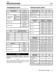
DTC P0107, P0108 5.19 - harley-davidson-sweden.se
DTC P0107, P0108 5.19 - harley-davidson-sweden.se
DTC P0107, P0108 5.19 - harley-davidson-sweden.se

Create successful ePaper yourself
Turn your PDF publications into a flip-book with our unique Google optimized e-Paper software.
HOME<br />
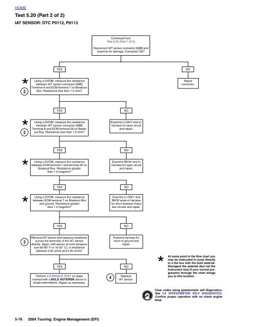
Test 5.20 (Part 2 of 2)<br />
IAT SENSOR: <strong>DTC</strong> P0112, P0113<br />
Continued from<br />
Test 5.20 (Part 1 of 2).<br />
Disconnect IAT <strong>se</strong>nsor connector [89B] and<br />
examine for damage. Connector OK<br />
YES<br />
NO<br />
2<br />
Using a DVOM, measure the resistance<br />
between IAT <strong>se</strong>nsor connector [89B]<br />
Terminal A and ECM terminal 7 on Breakout<br />
Box. Resistance less than 1.0 ohm<br />
Repair<br />
connector.<br />
YES<br />
NO<br />
2<br />
Using a DVOM, measure the resistance<br />
between IAT <strong>se</strong>nsor connector [89B]<br />
Terminal B and ECM terminal 26 on Breakout<br />
Box. Resistance less than 1.0 ohm<br />
Examine Lt GN/Y wire in<br />
harness for open circuit<br />
and repair.<br />
YES<br />
NO<br />
Using a DVOM, measure the resistance<br />
between ECM terminal 7 and terminal 26 on<br />
Breakout Box. Resistance greater<br />
than 1.0 megohm<br />
Examine BK/W wire in<br />
harness for open circuit<br />
and repair.<br />
YES<br />
NO<br />
Using a DVOM, measure the resistance<br />
between ECM terminal 7 on Breakout Box<br />
and ground. Resistance greater<br />
than 1.0 megohm<br />
Examine Lt GN/Y and<br />
BK/W wires in harness<br />
for short between the<strong>se</strong><br />
two circuits and repair.<br />
YES<br />
NO<br />
3<br />
Remove IAT <strong>se</strong>nsor and measure resistance<br />
across the terminals of the IAT <strong>se</strong>nsor<br />
directly. Again, with <strong>se</strong>nsor at room temperature<br />
60-90° F or 16-32° C), is resistance<br />
between 2.0k ohms and 5.0k ohms<br />
Examine harness for<br />
short to ground and<br />
repair.<br />
YES<br />
Perform 5.8 WIGGLE TEST on steps<br />
marked with a BOLD ASTERISK above to<br />
locate intermittents. Repair as necessary.<br />
4<br />
NO<br />
Replace<br />
IAT <strong>se</strong>nsor.<br />
At some point in the flow chart you<br />
may be instructed to jump directly<br />
to a the box with the bold asterisk.<br />
Disregard the asterisk (but not the<br />
instruction box) if your normal progression<br />
through the chart brings<br />
you to this location.<br />
Clear codes using speedometer <strong>se</strong>lf diagnostics.<br />
See 5.6 SPEEDOMETER SELF DIAGNOSTICS.<br />
Confirm proper operation with no check engine<br />
lamp.<br />
5-76 2004 Touring: Engine Management (EFI)