HARMON ROCKET III - Green Hobby & Model
HARMON ROCKET III - Green Hobby & Model
HARMON ROCKET III - Green Hobby & Model

You also want an ePaper? Increase the reach of your titles
YUMPU automatically turns print PDFs into web optimized ePapers that Google loves.
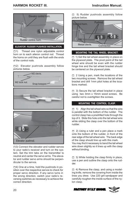
<strong>HARMON</strong> <strong>ROCKET</strong> <strong>III</strong>. Instruction Manual.<br />
Elevator control horn.<br />
! 5) Rudder pushrods assembly follow<br />
picture below.<br />
Control horn.<br />
Pushrod.<br />
Rudder control horn.<br />
ELEVATOR - RUDDER PUSHROD INSTALLATION.<br />
!1) Thread one nylon adjustable control<br />
horn on to each aileron control rod. Thread<br />
the horns on until they are flush with the ends<br />
of the control rods.<br />
!2) Elevator pushrods assembly follow<br />
pictures below.<br />
M2 lock nut.<br />
M2 clevis.<br />
Snap keepper.<br />
Metal clevis.<br />
Connector.<br />
MOUNTING THE TAIL WHEEL BRACKET.<br />
! 1) Set the tail wheel assembly in place on<br />
the plywood plate. The pivot point of the tail<br />
wheel wire should be even with the rudder<br />
hinge line and the tail wheel bracket should<br />
be centered on the plywood plate.<br />
! 2 Using a pen, mark the locations of the<br />
two mounting screws. Remove the tail wheel<br />
bracket and drill 1mm pilot holes at the locations<br />
marked.<br />
! 3) Secure the tail wheel bracket in place<br />
using two 3mm x 15mm wood screws. Be<br />
careful not to overtighten the screws.<br />
MOUNTING THE CONTROL CLASP.<br />
! 1) Align the tail wheel wire so that the wire<br />
is parallel with the bottom of the rudder. The<br />
control clasp has a predrilled hole through the<br />
top of it. Slide this hole onto the tail wheel wire<br />
while sliding the clasp over the bottom of the<br />
rudder.<br />
Elevator pushrod.<br />
!3) Connect the elevator and rudder servos<br />
to your radio’s receiver and turn on the system.<br />
Set the trim tabs on the transmitter to<br />
neutral and center the servo arms. The elevator<br />
and rudder servo arms should be perpendicular<br />
to the servos.<br />
!4) One at a time, hold the pushrods in position<br />
over the respective servos to check for<br />
proper servo direction. If any servo turns in<br />
the wrong direction, switch your radio’s reversing<br />
switches as necessary to achieve the<br />
correct direction.<br />
! 2) Using a ruler and a pen place a mark<br />
onto the bottom of the rudder, in front of the<br />
rear edge of the tail wheel wire. The back edge<br />
of the clasp should line up with this mark.<br />
You may find it necessary to bend the tail wheel<br />
wire down slightly so it lines up with the clasp<br />
without binding.<br />
! 3) While holding the clasp firmly in place,<br />
use a pen and outline the clasp onto the rudder.<br />
! 4) Remove the clasp, and using a modeling<br />
knife, remove the covering from inside the<br />
lines you drew. Use 220 grit sandpaper and<br />
carefully roughen the inside surface of the nylon<br />
clasp.<br />
20