USB-Synthesizer - SDR-Kits
USB-Synthesizer - SDR-Kits
USB-Synthesizer - SDR-Kits

You also want an ePaper? Increase the reach of your titles
YUMPU automatically turns print PDFs into web optimized ePapers that Google loves.
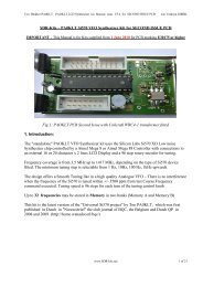
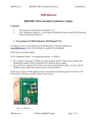
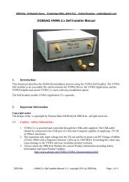
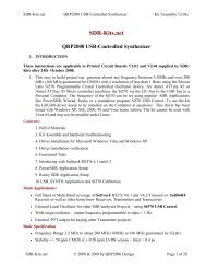
<strong>SDR</strong>-<strong>Kits</strong>.net QRP2000 <strong>USB</strong>-Controlled <strong>Synthesizer</strong> Kit Assembly v1.35<br />
1. INTRODUCTION<br />
<strong>SDR</strong>-<strong>Kits</strong>.net<br />
QRP2000 <strong>USB</strong>-Controlled <strong>Synthesizer</strong><br />
This easy to build project can generate almost any frequency between 3.5MHz and up to 160 MHz<br />
and higher with a resolution of 1 Herz or less using the Silicon Labs Si570 Programmable Crystal<br />
Controlled Oscillator device. An Atmel ATTiny 45 Micro controller interfaces the Si570 via the I2C<br />
bus to the <strong>USB</strong> bus to a Personal Computer. The frequency of the Si570 can be set using an<br />
Application like Power<strong>SDR</strong>, which may be downloaded from Sourceforge Website or a standalone<br />
program Si570 <strong>USB</strong> Control, supplied as hostware.<br />
Contents:<br />
2. Bill of Materials<br />
3. Kit Assembly<br />
4. Driver Installation for Microsoft Windows XP<br />
5. Driver installation verification<br />
6. Functional Tests<br />
7. Interfacing with Softrock RXTX 6.1 and 6.2<br />
8 Power<strong>SDR</strong> Setup<br />
9 Rocky <strong>SDR</strong> Application Setup<br />
Main Applications:<br />
• CMOS Kit: Full Band or Multi Band coverage of Softrock RXTX V6.1 and V6.2 Transceiver<br />
• External Local Oscillator for other <strong>SDR</strong> hardware Projects – using Power<strong>SDR</strong> application<br />
• Wide range oscillator – output frequency programmable in steps < 1 Hz.<br />
• External /PTT output for other projects<br />
Basic Specification:<br />
• Frequency Range 3.5 MHz to 1400 MHz (10MHz to 160 MHz guaranteed by SiLab<br />
• Stability +/- 50 ppm CMOS or +/0 20 ppm LVDS version – Jitter < 0.4 ps<br />
• Output: Square wave : CMOS version 2.6V pk-pk 15pF , LVDS version 0.7V pk-pk into 100<br />
Ohm<br />
• Power Supply: <strong>USB</strong> Powered or +5V to +12V Power Supply – approx 80mA for Si570 CMOS<br />
version, or 100mA for Si570 LVDS version<br />
• PCB size 41 x 48 mm<br />
<strong>SDR</strong>-<strong>Kits</strong>.net © 2008 by QRP2000 Design Page 1 of 22
<strong>SDR</strong>-<strong>Kits</strong>.net QRP2000 <strong>USB</strong>-Controlled <strong>Synthesizer</strong> Kit Assembly v1.35<br />
Acknowledgments: This project was designed by QRP2000 Design team:<br />
Tom - DG8SAQ – Firmware and Host Application<br />
Guido PE1NNZ and Alan M0PUB - Power<strong>SDR</strong> Support Of <strong>USB</strong> Interface<br />
John G8BTR – PCB Design Steve G0XARBeta build – Documentation review<br />
Jan G0BBL – Hardware design – Documentation – Kit Production<br />
Thanks also to Alex VE3NEA who kindly provided Rocky <strong>USB</strong> support for this project<br />
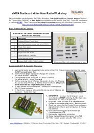
2. BILL OF MATERIALS<br />
QRP2000 Design – <strong>USB</strong> LO SYNTHESIZER - BOM<br />
Pcs/kit Designation Value Remarks<br />
2 C1, C10 10uF 16V Radial<br />
9<br />
C2, C3, C5. C6, C7,<br />
C8, C9 + 2 spare 0.1uF 0805 SMD<br />
1 C4 1nF 0805 SMD Marked black<br />
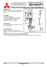
1 D1 1N4001<br />
2 D2, D3 3.6V Zener BZX55-3V6 500mW<br />
1 J1 <strong>USB</strong>-B Socket<br />
1 JP1a shorting jumper 0.1”<br />
1 JP1 3 pin header male 0.1” (Power selection <strong>USB</strong> or12V)<br />
1 JP2 2 pin header male 0.1” (RF Output connector)<br />
2 R1, R2 68 Ohm 0.4W (red red black brown brown)<br />
1 R3 2k2 0.4W Axial (red red black brown brown)<br />
1 R4 1M 0.4W (brown black black yellow brown)<br />
6<br />
R5, R6, R7, R8,<br />
R11, R12 4k7 0.4W (yellow violet black brown brown)<br />
0 R9, R10 0.00 Wirelink (Not supplied)<br />
1 U1 ATTiny45-20PU DG8SAQ FW<br />
1 U2 Si570CAC000141DG CMOS (Or Si570BBC000141DG as<br />
1 U3 LF33ABV Regulator TO220<br />
1 PCB <strong>USB</strong>-LO <strong>Synthesizer</strong> QRP2000 Design<br />
1 IC Socket 8 pin DIL<br />
5 PCB pins 1mm dia<br />
Please note:<br />
J2 and T1 are optional and therefore not supplied<br />
( ) Inventory of Kit parts is highly recommended – see Fig 1 below.<br />
Caution: Please observe antistatic precautions for semiconductor devices<br />
Do not remove Si570 device from anti-static bag until needed<br />
Note: If you have a question about the kit. please contact Jan G0BBL via sdrkits @ gmail.com<br />
(remove all spaces in email address)<br />
<strong>SDR</strong>-<strong>Kits</strong>.net © 2008 by QRP2000 Design Page 2 of 22
<strong>SDR</strong>-<strong>Kits</strong>.net QRP2000 <strong>USB</strong>-Controlled <strong>Synthesizer</strong> Kit Assembly v1.35<br />
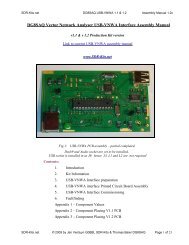
Fig 1 Inventory of Kit Parts – (photo by Steve G0XAR)<br />
3. KIT ASSEMBLY<br />
Introduction:<br />
Making this kit will involve the soldering of surface mount components. This is not difficult but some<br />
care and patience is needed. You will need a well lit and clear work surface, a suitable soldering iron<br />
with a small tip, some fine (for example 24SWG – 0.5mm) resin cored solder and a pair of long<br />
tweezers, The type of tweezers should allow you to hold the component GENTLY, otherwise the your<br />
tweezers may act as a rocket launcher for tiny SMD parts!!. Firstly make sure that the PCB is held<br />
securely to the work surface so it does not move around. Using "Blue Tack" on the edges of the board<br />
is one way of doing this. Then identify the pair of lands on the pcb that the surface mount component<br />
will be soldered to. Melt a small blob of solder on to one of the lands as a coat. Then, using the<br />
tweezers, pick up the the surface mount component and place it across the lands and melt the solder<br />
on the pre soldered land. This should effectively hold the component in place whilst you solder it to<br />
the unsoldered land. Then resolder it to the to the first land. Then check that the joints are good using a<br />
magnifying glass. This all sounds very complicated but it works in practice. If this is your first time<br />
using SMD you may wish to find a junk computer card and practice on it first. There are also a<br />
<strong>SDR</strong>-<strong>Kits</strong>.net © 2008 by QRP2000 Design Page 3 of 22
<strong>SDR</strong>-<strong>Kits</strong>.net QRP2000 <strong>USB</strong>-Controlled <strong>Synthesizer</strong> Kit Assembly v1.35<br />
number of excellent tutorials on the internet - and no you do not need an oven or an SM<br />
workstation. An ordinary soldering iron (preferably temperature controlled is good enough.<br />
Good luck – Viel spass – Veel plezier -<br />
Bottom PC mounted components<br />
Fig 2 PCB with all components except Si570 fitted at bottom of board<br />
Please note: floating pad C9 requires wire link to “CW Pin”<br />
( ) Remove any components from PCB so PCB is bare<br />
( ) Check Kit contents against Bill of Materials<br />
( ) Place PCB upside down as in fig 2.<br />
( ) Look at Figure 2 to see the exact placement of the SMD capacitors C2, C3 and C5<br />
through C9, and the PCB terminals. The SMD Capacitors are the small oblong shapes<br />
(0805 package), the soldered ends of the PCB terminals show as shiny circles. Figure 1<br />
does NOT show C4 to avoid confusing it with C2. It looks exactly the same but has a different<br />
<strong>SDR</strong>-<strong>Kits</strong>.net © 2008 by QRP2000 Design Page 4 of 22
<strong>SDR</strong>-<strong>Kits</strong>.net QRP2000 <strong>USB</strong>-Controlled <strong>Synthesizer</strong> Kit Assembly v1.35<br />
value. Follow the instructions below exactly to avoid mistakes<br />
( ) Adjust Temperature of Temperature Controlled Soldering Station to correct temperature<br />
for soldering SMD components. Temperature depends on type of solder you are using<br />
( ) Solder SMD 0.1uF 0805 Capacitors C2, C3 and C5 through C9 as<br />
shown in Figure 2. Then check against Figure 2.<br />
( ) Solder C4 1nF 0805 Capacitor (identified with BLACK mark) next to C3 (Lower right hand<br />
side of the board<br />
( ) Check all joints – the board should look like fig 2 below<br />
( ) Note: The placing of the PCB pins are shown for to suit CMOS Si570 kit for Softrock<br />
RXTX. If you are using the kit for other purposes then solder PCB pins to suit your<br />
particular application.<br />
( ) Fit PCB terminals as shown in Fig 2 by pressing pin through PCB using a hard metal<br />
surface or long nose pliers making sure that you do NOT damage any of the SMD<br />
capacitors in the process and solder at Bottom layer . The location of the PCB terminals.<br />
Note: In the first production boards, two holes, one near C9 and also the RF output pin<br />
are smaller than 1mm and will need enlarging with a 1mm drill for the PCB pin to fit. If<br />
you enlarge the hole, cut the bottom of the pcb pin and solder the PCB pin at both sides<br />
to ensure solid connnection between the top and bottom tracks<br />
( ) In some versions of PCB, the track between PCB Terminal “CW” and left hand side of C9 is<br />
missing. If this is the case solder a short wire between “CW” pin and the floating t<br />
rack of C9 (see fig 2.)<br />
( ) Turn board over<br />
Components mounted on Top ~Layer of PCB (Top Silk)<br />
<strong>SDR</strong>-<strong>Kits</strong>.net © 2008 by QRP2000 Design Page 5 of 22
<strong>SDR</strong>-<strong>Kits</strong>.net QRP2000 <strong>USB</strong>-Controlled <strong>Synthesizer</strong> Kit Assembly v1.35<br />
Fig 3<br />
Component lay-out diagram<br />
Place the board so you can see the components side with the placement (silk screen) diagram in view.<br />
Orient the board so that the words "©2008 QRP Design” is at the top right.<br />
( ) 8 pin IC socket for U1 ensuring that the indentation on the end of the socket matches that on<br />
the silk screen<br />
( ) <strong>USB</strong> Socket – solder pins including the ground connections.<br />
( ) Mount D1, D2 and D3 -<br />
Note: observe cathode band and solder observing the polarity of the diode.<br />
For D1 the white band should be facing the hole closest to U3.<br />
For D2 and D3 the black band should be facing the holes next to <strong>USB</strong> socket J1.<br />
is not marked on the board so if in doubt consult the circuit diagram.<br />
The polarity<br />
( ) Mount Resistors R1 and R2 (68 Ohm blue grey black gold brown).<br />
Mount R3 (2K2 red red black brown brown).<br />
R4 (1M brown black black yellow brown).<br />
Mount R5, R6, R7, R8, R11 and R12 (4K7 yellow violet black brown brown)<br />
Note: When installing the resistors make sure you put the right values in the right<br />
places. If in doubt as to the value please check them first using a meter.<br />
( ) Fit Capacitor C1 (10uF) and C10 (10uF) – Note: observe polarity and solder<br />
( ) Solder two links (discarded resistor wires) in R9 and R10<br />
<strong>SDR</strong>-<strong>Kits</strong>.net © 2008 by QRP2000 Design Page 6 of 22
<strong>SDR</strong>-<strong>Kits</strong>.net QRP2000 <strong>USB</strong>-Controlled <strong>Synthesizer</strong> Kit Assembly v1.35<br />
( ) Caution: when handling semiconductors observe anti-static precautions:<br />
Preferably wear anti-static Strap or touch unpainted metal ground before<br />
semiconductors<br />
handling<br />
( ) Fit transistor Q1 – Note: observe position against top silk and solder<br />
( ) Fit U3 (LF33ABV) – Note: observe correct position against top silk and solder<br />
( ) Fit Connector JP1 (3 pin) and solder<br />
( ) Fit 2 pin Output Connector and solder –<br />
LVDS Transformer T1 (supplied with complete Si570 LVDS Kit only<br />
( ) Cut enamelled wire in 3 pieces of 18 cm (7 inches) each and twist uniformly to 4 turns per cm<br />
( ) Wind 5 turns trifiliar on 43BN2402 supplied.<br />
( ) Scrape and tin end of enamelled wire and fit T1 on PCB if required.<br />
Interim Test Procedure<br />
Note: Jumper 1 is used to set the source of the power for the board. If it is next to the diode<br />
the source is supplied from the external power line, if in the alternative position the<br />
power is supplied from the <strong>USB</strong> port<br />
( ) Set Jumper JP1 to pin next to Diode D1<br />
( ) Connect 5-12V DC Power to PCB – Note: observe polarity<br />
( ) Check Voltage on U3 pin 3 to Ground - Note: reading should be 3.3V +/- 0.1V<br />
( ) Remove Power to PCB<br />
( ) Caution: observe anti-static precautions handling semiconductor<br />
( ) Plug ATTiny45 U1 into IC holder – pin 1 should be aligned towards U1 on the top silk<br />
( ) Connect <strong>USB</strong> <strong>Synthesizer</strong> to <strong>USB</strong> socket of a Personal Computer and measure voltage<br />
between U1 Pin 8. Reading should be 4.9 – 5.1V<br />
( ) Disconnect <strong>USB</strong> cable from <strong>USB</strong> <strong>Synthesizer</strong><br />
Final assembly of Si570 Device<br />
( ) Caution: observe antistatic precautions handling semiconductors<br />
<strong>SDR</strong>-<strong>Kits</strong>.net © 2008 by QRP2000 Design Page 7 of 22
<strong>SDR</strong>-<strong>Kits</strong>.net QRP2000 <strong>USB</strong>-Controlled <strong>Synthesizer</strong> Kit Assembly v1.35<br />
( ) The Si570 device is soldered on the bottom of the PCB<br />
( ) Locate the Dot marking on the Si570 device and align with pin 1 marked on the PCB and<br />
solder<br />
Fig 4 Location of S570 chip – dot bottom left pin is Pin 1<br />
( ) Note: take care soldering the connections of U2 pin 7 and pin 8. if there is not enough<br />
copper, then remove some of the solder-resist from the tracks to ensure a good joint.<br />
Final Test and commissioning<br />
( ) Set Jumper JP1 to pin 1 and 2 next to Diode D1 (External Power supply)<br />
( ) Connect PCB to a 5-12V DC Power Supply and measure Current Consumption typically<br />
should be around 70-85mA<br />
( ) Set Jumper JP1 to pin 2 and 3 towards letters “JP1” on PCB (<strong>USB</strong> Powered)<br />
THIS COMPETES KIT ASSEMBLY<br />
<strong>SDR</strong>-<strong>Kits</strong>.net © 2008 by QRP2000 Design Page 8 of 22
<strong>SDR</strong>-<strong>Kits</strong>.net QRP2000 <strong>USB</strong>-Controlled <strong>Synthesizer</strong> Kit Assembly v1.35<br />
4. DRIVER INSTALLATION PROCEDURE MICROSOFT XP<br />
• Download Si570_Firmware from: http://www.mydarc.de/dg8saq/SI570/index.shtml<br />
• Press “Save target as”<br />
• Unzip the file SI570_firmware.zip<br />
The following directories will be created<br />
Driver Installation Procedure<br />
• Plug in the <strong>USB</strong>-<strong>Synthesizer</strong> module into <strong>USB</strong> port<br />
• The following Screen should be displayed:<br />
<strong>SDR</strong>-<strong>Kits</strong>.net © 2008 by QRP2000 Design Page 9 of 22
<strong>SDR</strong>-<strong>Kits</strong>.net QRP2000 <strong>USB</strong>-Controlled <strong>Synthesizer</strong> Kit Assembly v1.35<br />
Problem solving: If this screen is NOT displayed<br />
• Check the <strong>USB</strong>-<strong>Synthesizer</strong> hardware for correct operation<br />
• Is ATTiny45-20 microprocessor plugged in correctly<br />
• Has ATTiny45-20 been loaded with correct firmware<br />
• Connect the <strong>USB</strong>-<strong>Synthesizer</strong> to the <strong>USB</strong> port of a different computer<br />
After about 5 seconds the message below should be displayed:<br />
<strong>SDR</strong>-<strong>Kits</strong>.net © 2008 by QRP2000 Design Page 10 of 22
<strong>SDR</strong>-<strong>Kits</strong>.net QRP2000 <strong>USB</strong>-Controlled <strong>Synthesizer</strong> Kit Assembly v1.35<br />
• Select “No, not this time”<br />
• Press “NEXT”<br />
The following screen should now be displayed:<br />
Deselect “Install the software automatically”<br />
Select “install from a list or specific location”<br />
Press “Next>”<br />
The following screen is displayed<br />
<strong>SDR</strong>-<strong>Kits</strong>.net © 2008 by QRP2000 Design Page 11 of 22
<strong>SDR</strong>-<strong>Kits</strong>.net QRP2000 <strong>USB</strong>-Controlled <strong>Synthesizer</strong> Kit Assembly v1.35<br />
• Deselect “Search removable Media”<br />
• Select “Include this location in the search”<br />
• Press “Browse”<br />
• Select Folder AVR-<strong>USB</strong>-Driver as shown below<br />
• Click “Ok”<br />
• Press “Next>”<br />
• Software is being installed<br />
<strong>SDR</strong>-<strong>Kits</strong>.net © 2008 by QRP2000 Design Page 12 of 22
<strong>SDR</strong>-<strong>Kits</strong>.net QRP2000 <strong>USB</strong>-Controlled <strong>Synthesizer</strong> Kit Assembly v1.35<br />
When successfully installed, following message displayed:<br />
Click “Finish”<br />
Message displayed “Found New hardware successfully installed”<br />
END OF DRIVER INSTALLATION PROCEDURE<br />
<strong>SDR</strong>-<strong>Kits</strong>.net © 2008 by QRP2000 Design Page 13 of 22
<strong>SDR</strong>-<strong>Kits</strong>.net QRP2000 <strong>USB</strong>-Controlled <strong>Synthesizer</strong> Kit Assembly v1.35<br />
5. DRIVER INSTALLATION VERIFICATION<br />
A check can be made at any time if the driver is properly installed but only if the<br />
<strong>USB</strong>-module is plugged in<br />
• Press “START”<br />
• Press “Control Panel”<br />
• Select “System”<br />
Following Screen is displayed<br />
• Select “Hardware”<br />
• Select “Device Manager”<br />
A folder “Lib<strong>USB</strong>-Win32 Devices” should be displayed<br />
(only when <strong>USB</strong>-<strong>Synthesizer</strong> is Plugged-in)<br />
• Press to Expand AVR-<strong>USB</strong> Device folder<br />
<strong>SDR</strong>-<strong>Kits</strong>.net © 2008 by QRP2000 Design Page 14 of 22
<strong>SDR</strong>-<strong>Kits</strong>.net QRP2000 <strong>USB</strong>-Controlled <strong>Synthesizer</strong> Kit Assembly v1.35<br />
Click on “AVR <strong>USB</strong> Device”<br />
Proper operation of the Driver may now be checked<br />
• Select tab “Driver”<br />
The screen below is displayed and options made available to<br />
• Remove Driver<br />
• Update Driver<br />
• Reinstall Driver<br />
<strong>SDR</strong>-<strong>Kits</strong>.net © 2008 by QRP2000 Design Page 15 of 22
<strong>SDR</strong>-<strong>Kits</strong>.net QRP2000 <strong>USB</strong>-Controlled <strong>Synthesizer</strong> Kit Assembly v1.35<br />
END OF DRIVER INSTALLATION VERIFICATION<br />
6. FUNCTIONAL TESTS<br />
Once driver is installed the <strong>USB</strong> <strong>Synthesizer</strong> board can be tested with the application “PROJECT 1”<br />
which is located in folder “Si570/hostware”<br />
Start “Project 1”<br />
Check SI570 i2c adr is set as follows<br />
LVDS Si570BBC000141DG i2c address = 55 Hex<br />
CMOS Si570CAC000141DG i2c address = 55 Hex<br />
Click button “Test<strong>USB</strong>”<br />
The following screen should be shown.<br />
<strong>SDR</strong>-<strong>Kits</strong>.net © 2008 by QRP2000 Design Page 16 of 22
<strong>SDR</strong>-<strong>Kits</strong>.net QRP2000 <strong>USB</strong>-Controlled <strong>Synthesizer</strong> Kit Assembly v1.35<br />
Setting Frequency:<br />
Enter the desired frequency in the Window MHz<br />
Example frequency entered 16.400 MHz<br />
click “set freq by value”<br />
click “read SI570 registers”<br />
Following screen should be displayed<br />
<strong>SDR</strong>-<strong>Kits</strong>.net © 2008 by QRP2000 Design Page 17 of 22
<strong>SDR</strong>-<strong>Kits</strong>.net QRP2000 <strong>USB</strong>-Controlled <strong>Synthesizer</strong> Kit Assembly v1.35<br />
END OF FUNCTIONAL TEST PROCEDURE<br />
7. INTERFACING TO SOFTROCK RXTX V6.1 or V6.2 TRANSCEIVER<br />
Three connections are required to connect the <strong>USB</strong>-<strong>Synthesizer</strong> to the RXTX V6.x transceiver as<br />
follows:<br />
( ) Prepare a 10cm (4 inch) length of RG174 miniature coaxial cable by removing 1 cm plastic at<br />
either end of the cable. Next remove 3mm insulation from the inner conductor at both ends.<br />
Fig 5: Preparation of 10cm 4 inch Coaxial cable<br />
( ) On RXTX PCB, disable the Crystal Oscillator by removing 2 pin Jumper from JP2.<br />
( ) On RXTX PCB remove 2 pin Jumper from JP1.<br />
( ) Solder Inner conductor of coaxial cable to JP1 pin 2 as shown in fig 5 below:<br />
<strong>SDR</strong>-<strong>Kits</strong>.net © 2008 by QRP2000 Design Page 18 of 22
<strong>SDR</strong>-<strong>Kits</strong>.net QRP2000 <strong>USB</strong>-Controlled <strong>Synthesizer</strong> Kit Assembly v1.35<br />
( ) Solder Outer conductor of coaxial cable to JP1 pin 4 (Ground) as shown below.<br />
Fig 6: Connection of Coaxial Cable to RXTX PCB JP1<br />
( ) On <strong>USB</strong> <strong>Synthesizer</strong> board solder inner conductor of coax cable to pin A<br />
( ) Solder outer braid of coax cable to centre pin B<br />
( ) Connect wire from +12V terminal to +12VDC terminal of RXTX PCB<br />
( ) Connect wire from <strong>USB</strong>-<strong>Synthesizer</strong> “PTT” to RXTX PCB “PTT_IN”<br />
www.<strong>SDR</strong>-kits.net<br />
+12V from<br />
RXTX<br />
To PTT_In on<br />
RXTX PCB<br />
A: Inner Coax<br />
B: outer braid<br />
Fig 7: Connections on <strong>USB</strong>-<strong>Synthesizer</strong> PCB to support Softrock RXTX<br />
8 Power<strong>SDR</strong> SETUP FOR RXTX <strong>USB</strong> SUPPORT<br />
<strong>SDR</strong>-<strong>Kits</strong>.net © 2008 by QRP2000 Design Page 19 of 22
<strong>SDR</strong>-<strong>Kits</strong>.net QRP2000 <strong>USB</strong>-Controlled <strong>Synthesizer</strong> Kit Assembly v1.35<br />
( ) Download Power<strong>SDR</strong> application from sourceforge<br />
http://powersdr-sr40.sourceforge.net/ and install as per instructions<br />
Beta versions may be posted on www.<strong>SDR</strong>-<strong>Kits</strong>.net website<br />
( ) After installation select “Setup” and tick “Si570 VFO on <strong>USB</strong>, Set Multiplier to “4” and<br />
enter Fxtal (Hz) to 114324000 and select “Apply”<br />
Fig 8: Power<strong>SDR</strong> <strong>USB</strong> setup Screen<br />
Note: Your existing CW keying arrangements (Parallel port or Serial port) as documented in the<br />
Power<strong>SDR</strong> documentation continues to be supported. The use of the <strong>USB</strong>-<strong>Synthesizer</strong> - Straight CW<br />
Key-input is optional.<br />
8.1 Si570 FREQUENCY CALIBRATION<br />
Definitions:<br />
Fa = Actual Receive Frequency (Frequency of known Radio Station or Radio Signal published in<br />
Frequency list or measured )<br />
Ft = Frequency entered to receive the “known Radio Station”<br />
Fxo = Frequency of the Si570 internal Crystal used in calculate and set “Ft”<br />
Fxn = Corrected Frequency of the Si570 Internal Crystal to set “Ft” to the same frequency as “Fa”<br />
Formula to calculate Fxn = Fxo – (Ft – Fa) / Fa * Fxo<br />
<strong>SDR</strong>-<strong>Kits</strong>.net © 2008 by QRP2000 Design Page 20 of 22
<strong>SDR</strong>-<strong>Kits</strong>.net QRP2000 <strong>USB</strong>-Controlled <strong>Synthesizer</strong> Kit Assembly v1.35<br />
Example =<br />
Fxo = 114,300.500 kHz<br />
Fa = 10,000.000 kHz<br />
Ft = 9,995.355 kHz<br />
(WWV reception on 10 MHz)<br />
Frequency set to receive WWV<br />
Fxn = 114,353.593 (Corrected Crystal frequency – which<br />
should be stored (in Hz) for future use by<br />
the program)<br />
9 Rocky V3.5 Setup<br />
The popular Rocky <strong>SDR</strong> Program by Alex VE3NEA may be downloaded from:<br />
http://www.dxatlas.com/Rocky/<br />
To enable <strong>USB</strong> Support, Start Rocky, Select “VIEW”, Select “Setting”, Select “DSP”<br />
Tick “Use Si570-<strong>USB</strong>, Tick “Multi-Band” and Check Address is set to “85” press “ok”<br />
Fig 9: Rocky <strong>USB</strong> setup Screen<br />
Note: Your existing CW keying arrangements (Parallel port or Serial port) as documented in the<br />
Rocky documentation is still supported. The use of the <strong>USB</strong>-<strong>Synthesizer</strong> - Straight CW Key-input is<br />
optional.<br />
END OF DOCUMENT<br />
<strong>SDR</strong>-<strong>Kits</strong>.net © 2008 by QRP2000 Design Page 21 of 22
<strong>SDR</strong>-<strong>Kits</strong>.net QRP2000 <strong>USB</strong>-Controlled <strong>Synthesizer</strong> Kit Assembly v1.35<br />
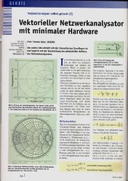
Fig 9<br />
<strong>USB</strong> <strong>Synthesizer</strong> Circuit Diagram<br />
<strong>SDR</strong>-<strong>Kits</strong>.net © 2008 by QRP2000 Design Page 22 of 22