
You also want an ePaper? Increase the reach of your titles
YUMPU automatically turns print PDFs into web optimized ePapers that Google loves.
TO ADJUST THE MITER BASE<br />
See Figure 33.<br />
Remember: Check all sett<strong>in</strong>gs before loosen<strong>in</strong>gscrews<br />
for the foflowfng procedures.Once screws have bean<br />
toosened, these sett<strong>in</strong>gsmust be reset.<br />
Eight screws ere visible on the miter base (B).<br />
• Four screws (k")o_eon the holderplates and secure<br />
these platesto the rails. It is not necessaryto loosenor<br />
adjust these screws forthis adjustment procedure.<br />
• Another pair of screws (L)is <strong>in</strong> the base, at the rear.<br />
Loosen these two screws(I-) end the rear miter (ock<strong>in</strong>g<br />
o[amps (M).<br />
• The last paZrof screws is located on the <strong>in</strong>fesdside of<br />
the base. Loosenthe left screw (N) only,<br />
• The right screw (O)will be usedas a pivot po<strong>in</strong>t.<br />
NOTE: The fTonttWOmiter lock<strong>in</strong>g c(amps (P)and rail<br />
clarnps shouldrem_n locked.<br />
• Adjustthe miter base so that it is parallelto the blade<br />
see To Check Miter Base Parsltellm'n.<br />
• Retighten the [eftfi'ont screw (N).<br />
• Clamp the rearmiter Lock<strong>in</strong>gclamps (M).<br />
• Retighten the two rear screws (L).<br />
M<br />
K<br />
M L<br />
K<br />
SLIDES<br />
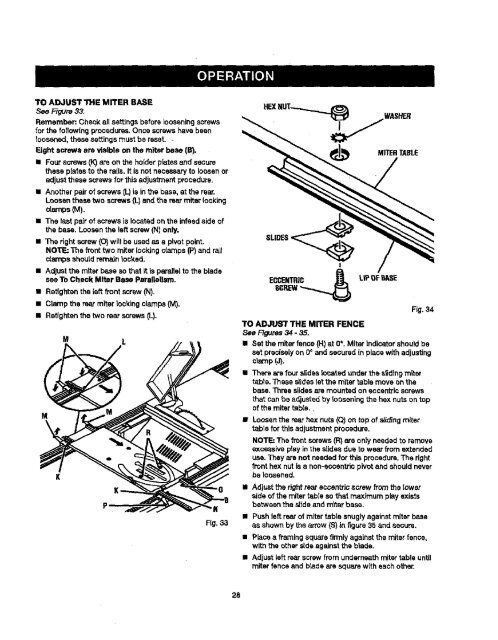
TO ADJUST THE MITER FENCE<br />
See F_Jras 34 - 35.<br />
MITER<strong>TABLE</strong><br />
Fig. 34<br />
II Set the miter fence (H) at 0°. Miter <strong>in</strong>dicatorshould be<br />
set preciselyon 0° and secured <strong>in</strong> place with adjust<strong>in</strong>g<br />
cl_¢np(J).<br />
• Ther_ are four slideslocated underthe s_d<strong>in</strong>gmiter<br />
ta,ble. These slideslet the miter table move onthe<br />
base. Three slidesare mounted on eccentricscrews<br />
that can be adjustedby loosen<strong>in</strong>gthe hex nutson top<br />
of the mitertable.,<br />
• Loosenthe rearhex nuts (Q)on top of slid<strong>in</strong>gmiter<br />
table for thisadjustmentprocadure.<br />
NOTE: The front screws (R)are ontyneeded to remove<br />
excessive play <strong>in</strong> the slides due to wear from extended<br />
use. They are not neededfor this procedure.The right<br />
front hex nutis a non-eocantricpivot and should never<br />
be ;oasened.<br />
• Adjustthe rightrear eccantrJcscrew fromthe lower<br />
side of the miter table so that maximum play exists<br />
betweenthes_ideand m'ftarbase.<br />
• Pushleft rear of miter table snugly aga<strong>in</strong>st miterbase<br />
Fig.33 as shown by the arrow (S) <strong>in</strong> figure 35 and secure,<br />
28<br />
• P_ca a fi_'nlng square firmlyaga<strong>in</strong>st the miterfence,<br />
with the other ,rideaga<strong>in</strong>stthe blade.<br />
• Adjust left rear screw from undern_th mitertable until<br />
miter fence end brads are square with each other,