
Create successful ePaper yourself
Turn your PDF publications into a flip-book with our unique Google optimized e-Paper software.
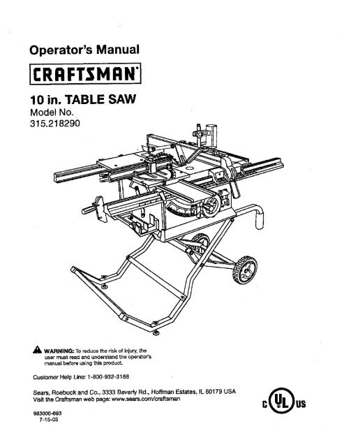
Operator's Manual<br />
<strong>10</strong> <strong>in</strong>. <strong>TABLE</strong> <strong>SAW</strong><br />
Model No,<br />
315.218290<br />
_k WARNING: To reduce the risk of <strong>in</strong>jury,the<br />
user must read and understandthe operator's<br />
manual before us<strong>in</strong>gthis product.<br />
Customer Help L<strong>in</strong>e: 1-800-932-3188<br />
Seam, Roebuck and Co., 3333 BeverPy Rd., Hoffman Estates, IL 60179 USA<br />
Visit the Craftsman web page: www.seam.com!cmffsman<br />
983000-693<br />
7-15-05
Warranty ............................................................................................................................................................................ 2<br />
Introduction....................................................................................................................................................................... 2<br />
GenareJSafety Rules......................................................... ............................................................................................ S--4<br />
Specific Sat°styRules.................................... ................................................................................................................. 4-5<br />
Symbols......................................................................................................................................................................... 6-7<br />
EIac_ca( ............................................................................................................................................................................ 6<br />
Glossary of Tsn'ns.............................................................................................................................................................. g<br />
Features..................................................................................................................................................................... <strong>10</strong>-13<br />
ToolsNeeded ................................................................................................................................................................. 13<br />
Loose Parts ............................................................................................................................................................... 14-15<br />
Assembly................................................................................................................................................................... 16-22<br />
Operation................................................................................................................................................................... 22-39<br />
Adjustments .............................................................................................................................................................. 40-44"<br />
Ma<strong>in</strong>tenance................................................................................................................................................................... 45<br />
Accessories.................................................................................................................................................................... 46<br />
Troubleshoot<strong>in</strong>g......................................................................................................................................................... 46-47<br />
Exploded View ........................................................................................................................................................... 4-8-57<br />
Parts Order<strong>in</strong>g/Service...................................................................................................................................... Back Page<br />
ONE YEAR FULL WARRANTY ON CRAFTSMAN TOOL<br />
If this Craftsman tool fails due to a defect <strong>in</strong> material or workmanshipwith<strong>in</strong>one year from the date of purchase,Call<br />
1-B00-4-MY-I-IOME O to arrangefor free repalr.If thlstool is used for commercial or rental purposes, thiswarranty will<br />
apply for only n<strong>in</strong>ety days from the date of purohass.This warranty appilesonly while this product is <strong>in</strong> the United States.<br />
This warranty givesyou specific legal rights, and you may eJso hays other rightswhich vary from stats to state.<br />
Seam, Roebuck and Co., Dept. 8t7WA, Hoffman Estates, IL 60179<br />
This tool has many featuresfor mak<strong>in</strong>gits use more pleasant and enjoyable.Safety, performance,and dependability<br />
have been giventop priority<strong>in</strong> the design of this productn'_.k<strong>in</strong>git easy to ma<strong>in</strong>ta<strong>in</strong> and operate.<br />
2
_k WARNING." Reed and understand all <strong>in</strong>sb'uetions,<br />
Failureto re[low all <strong>in</strong>struckions{istadbelow,<br />
may resutt<strong>in</strong> electric shock, fire andlor serious<br />
personal <strong>in</strong>jury.<br />
READ ALL iNSTRUCTIONS<br />
• KNOW YOUR POWER TOOL. Read the operator's<br />
manual carefully.Learn the saw's applicationsand<br />
Iimftations aswet[es the specific potenti_ hazards<br />
related to thistool.<br />
• GUARD AGAINST ELECTRICAL SHOCK BY PRE-<br />
VENTING BODY CONTACT WITH GROUNDED<br />
SURFACES- For examp}e,pipes, radiators,ranges,<br />
refrigeratorenclesures.<br />
• KEEP GUARDS IN PLACE and <strong>in</strong>good work<strong>in</strong>g order.<br />
• REMOVE ADJUSTING KEYS AND WRENCHES.<br />
Form habit of check<strong>in</strong>gto see that keysand adjust<strong>in</strong>g<br />
wrenches are removedfrom tool before turn<strong>in</strong>git on.<br />
• KEEP WORK AREA CLEAN. Cluttered areas and<br />
benches <strong>in</strong>viteaceidents. DO NOT leave tools or<br />
pieces ot wood onthe sawwhile it is <strong>in</strong>operation.<br />
• DO NOT USE IN DANGEROUS ENVIRONMENTS.<br />
Do not usepower tools <strong>in</strong> damp or wet locationsor<br />
exposeto ra<strong>in</strong>.Keep the work areaweI_s_.<br />
• KEEP CHILD REN AND VISITORS AWAY.All visitors<br />
shouldwear safetyg_aesasand be kept a safe<br />
distancefromwork ares. Do not let visitorsosntact<br />
tool or extensioncord while operat<strong>in</strong>g.<br />
• MAKE WORKSHOP CHILDPROOF with padlocksand<br />
master switches, orby remov<strong>in</strong>gs_,_'terkeys.<br />
• DON'T FORCE TOOL. It will do the job better and<br />
safer at the feed rote for which it was designed.<br />
• USE RIGHT TOOL, Don't rome the tool or attachment<br />
to do a job it was not designedfor. Don't use it for a<br />
purposenot <strong>in</strong>tended.<br />
• USE THE PROPER EXTENSION CORD. Make sure<br />
your extensioncord is <strong>in</strong> good condition.Use on[ya<br />
cordheavyenoughto carrythecurrentyourprodu_<br />
will draw. An undersizedcord will cause a drop <strong>in</strong>l<strong>in</strong>e<br />
voltage result<strong>in</strong>g<strong>in</strong>_oesof power and overheat<strong>in</strong>g.A<br />
wire gauges'_e (A.W.G.)of at least 14 is recommended<br />
for an extensioncord 25 feet or less <strong>in</strong> length. If <strong>in</strong><br />
doubt, use thenext heavier gauge.The smallerthe<br />
gauge number, the heavierthe cord.<br />
• DRESS PROPERLY.Do not wear loose cloth<strong>in</strong>g,<br />
gloves,neckties, orjewelry.They can get caught<br />
and draw you <strong>in</strong>tomov<strong>in</strong>g parts. Rubber glovesand<br />
nonskidfoo[wser are recommendedwhen work<strong>in</strong>g<br />
outdoors.Alse wear protecl:'Nehair osver;ng to conta<strong>in</strong><br />
long hak.<br />
• ALWAYSWEAR SAFETYG_ESWITI-I SIDE<br />
SHIELDS. Everyday eyeglasseshave onlyimpactresistantlenses,<br />
they are NOT safety gtaseas.<br />
• SECURE WORK, Use clamps oravise to hold work<br />
when pc_ctical._fs safert_n us<strong>in</strong>g your han_ an<br />
_ees both hands to operate tool.<br />
• DON'T OVERREACH. Keep properfoot<strong>in</strong>gand<br />
ba_nco at sit times.<br />
• MAINTAIN TOOLS WITH CARE. Kesptools sherp<br />
and clean for better and safer performanca.FoJiow<br />
<strong>in</strong>structionsfor lubricat<strong>in</strong>gand chang<strong>in</strong>gaccessories.<br />
• DISCONNECT TOOLS. When not<strong>in</strong> use, before<br />
servic<strong>in</strong>g,or when chang<strong>in</strong>gaLl_chmants,blades, bits,<br />
cutters, etc., an tools should be disconnected.<br />
• AVOID ACCIDENTAL STARTING. Be sureswitchis off<br />
when plugg<strong>in</strong>g <strong>in</strong> any tooL<br />
• USE RECOMMENDED ACCESSORIES. Consult the<br />
operator'smanual for recommendedaccessories.The<br />
use of improperaccessoriesmay risk<strong>in</strong>jury.<br />
• NEVER STAND ON TOOL, Serious<strong>in</strong>jurycouldoccur<br />
if the tool is tipped or if the cutt<strong>in</strong>gtoo[ is un<strong>in</strong>tention-<br />
_lly con_.cted.<br />
• CHECK DAMAGED PARTS. Before further use of<br />
the toot,a guard or other part that is damaged should<br />
be carefuttychecked to determ<strong>in</strong>ethat it will operate<br />
propedyand performits <strong>in</strong>tendedfunction. Check for<br />
al{gnn_ntof mov<strong>in</strong>gparts, b(n_<strong>in</strong>got mov<strong>in</strong>gparts,<br />
breakageof parts, mount<strong>in</strong>gand anyother conditioP.s<br />
that may affect its oparatien.A guardor o_er part _at<br />
is damaged must be properlyrepairedor replaced by<br />
_.nau'thofized service centerto avoid risk of personal<br />
ir_u_<br />
• USE THE RIGHT DIRECTION OF FEED. Feed work<br />
<strong>in</strong>to a blade or cutler aga<strong>in</strong>st the directionot rotation of<br />
bladeor cutter only.<br />
• NEVER LEAVE TOOL RUNNING UNATTENDED.<br />
TURN THE POWER OFF. Don't leave tool untilit<br />
comes to a complete stop,<br />
• PROTECT YOUR LUNGS. Wear a face or dust mask if<br />
the cutt<strong>in</strong>goperationis dusty.<br />
• PROTECT YOUR HEARING.Wear'hear<strong>in</strong>g protection<br />
dorJng exte_de_ periodsofopera,on,<br />
• DO NOT ABUSE CORD. Neveryank cord to disconnect<br />
from receptacle. Keep cord from heat, oil,and<br />
sharp edges.<br />
• USE OUTDOOR EXTENSION CORDS, When tool<br />
is usedou_oore, use onlyextensbn cordswith<br />
approved ground osnne_ion tha_are <strong>in</strong>tended for use<br />
outdoors and so m_rked.<br />
• ALWAYS KEEP THE BLADE GUARD AND RIVING<br />
KNIFE/SPREADER/SPLITTER IN PLACE and <strong>in</strong><br />
work<strong>in</strong>g order.<br />
• KEEP BLADES CLEAN, SHARP, ANDWITH<br />
SUFFICIENT SET. Sharp blades m<strong>in</strong>imize stall<strong>in</strong>g<br />
and kickback.<br />
• KEEP HANDS AWAY FROM CLrt-r|NG AREA. Keep<br />
hands away from blades. Do notreach underneath
work or around or overthe blade while blade is<br />
rotat<strong>in</strong>g.Do not attempt to removecut material when<br />
blade is mov<strong>in</strong>g.<br />
• BLADE COASTS AFTER BEING TURNED OFF,<br />
• NEVER USE IN AN EXPLOSIVE ATMOSPHERE.<br />
Normal spark<strong>in</strong>g of the motor Gould ignite fumes.<br />
• INSPECT TOOL CORDS PERIODICALLY. If damaged,<br />
have repaired by a qualified servicetechnicianat<br />
an authorizedservicefacility.The conductorwith<br />
<strong>in</strong>sulationhav<strong>in</strong>gan outer surfasethat is green with<br />
or without yellow sl:ipes is the equipment-ground-<br />
[ng conductor.If repair or replacementof the electric<br />
cord or plugis necessary,do not connect the equipment-ground<strong>in</strong>g<br />
conductor to a live term<strong>in</strong>al.Repair<br />
or replace a damaged orworn cord immediately.Stay<br />
constant_jaware of cord location and keep itwen away<br />
from the rotat<strong>in</strong>gblade.<br />
• INSPECT EXTENSION CORDS PERIODICALLY and<br />
replace if damaged.<br />
• GROUND ALL TOOLS. if tool is equippedwith threeprong<br />
plug, it should be plugged<strong>in</strong>to a thrse-ho_e<br />
electricalrace,oracle.<br />
• CHECKWlTH A QUALIFIED ELECTRICIAN or service<br />
personnelif the 9round<strong>in</strong>g <strong>in</strong>structionsare not completely<br />
understoodor if <strong>in</strong> doubt as to whether the tool<br />
is properly 9rounded.<br />
• USE ONLY CORRECT ELECTRICAL DEVICES: 3-wira<br />
e0_.tansioncords that have 3-prong ground<strong>in</strong>gplugs and<br />
3-pole receptaclesthat accept the tool's plug.<br />
• DO NOT MODIFYthe plugprovided. If it will not fit the<br />
outlet, have the proper outlet <strong>in</strong>stalled by a quatified<br />
etectndan.<br />
• KEEP TOOL DRY, CLEAN, AND FREE FROM OIL<br />
AND GREASE. Alwaysuse a c_eancloth when clean-<br />
• GUARD AGAINST KICKBACK. Kickback occurs<br />
when the blade stalls rapidly and workplace is driven<br />
beck tow_ds the o_arator. It can pullyour h_nd (nto<br />
the blade result<strong>in</strong>g<strong>in</strong> seriouspersonal<strong>in</strong>jury.Stay out<br />
oi blade path andturn switch off immedi_ely if blade<br />
b<strong>in</strong>dsors_iis,<br />
• USE RIP FENCE. Alwaysuse a fence orstraight edge<br />
guidewhen Hpp<strong>in</strong>g.<br />
• SUPPORT LARGE PANELS. Tom<strong>in</strong>imize riskof blade<br />
p<strong>in</strong>ch<strong>in</strong>gand kickback, always support large panels.<br />
• REMOVE ALL RENCES AND AUXILIARY <strong>TABLE</strong>S<br />
before transpo_ng saw. Failureto do so can result <strong>in</strong><br />
an accidsn.tcaus<strong>in</strong>gpose_le seriouspersonal<strong>in</strong>jury.<br />
• ALWAYS USE BLADE GUARD, RMNG KNIFE/<br />
SPREADEPJSPLrl-rER, AND ANTI-KICKBACK<br />
PAWLS on 81[=through-saw<strong>in</strong>g =operations. Through-<br />
4<br />
<strong>in</strong>g. Never use brake fluids, gasol<strong>in</strong>e,pe_'oleum-based<br />
products,or any soWantsto clean tool.<br />
• STAYALERT AND EXERCISE CONTROL. Watch<br />
what you are do<strong>in</strong>g and use common sense.Do not<br />
operate tool when you are tired. Do not rush.<br />
• DO NOT USE TOOL IFSWlTCH DOES NOT TURN IT<br />
ON AND OFF. Have defective switchesreplaced by an<br />
authorizedservtce center.<br />
• USE ONLY CORRECT BLADES. Do not use blades<br />
with <strong>in</strong>correct sizeholes. Neveruse blade washers or<br />
blade bo{Lsthat ere defective or <strong>in</strong>correct.The maximum<br />
blade capacity of your saw is <strong>10</strong> <strong>in</strong>. {254 ram).<br />
• BEFORE MAKING A CUT, BE SURE ALL ADJUST-<br />
MENTS ARE SECURE.<br />
• BE SURE BLADE PATH IS FREE OF NAILS. <strong>in</strong>spect<br />
for and remove allnails from lumber before cutt<strong>in</strong>g.<br />
• NEVER TOUCH BLADE or other mov<strong>in</strong>gparts dur<strong>in</strong>g<br />
USe.<br />
• NEVER STARTA TOOL WNEN ANY ROTATING COM-<br />
PONENT IS IN CONTACT WITH THE WORKPIECE.<br />
• DO NOT OPERATE A TOOL WHILE UNDER THE<br />
INFLUENCE OF DRUGS, ALCOHOL, OR ANY<br />
MEDICATION.<br />
• WHEN SERVICING use only identica]replacement<br />
parts. Use of any other partsmay create a hazard or<br />
cause product damage.<br />
• USE ONLY RECOMMENDED ACCESSORIES listed<br />
<strong>in</strong> this manual or addendums. Use of accessories<br />
that are not listed may cause the risk of personal<br />
<strong>in</strong>jury. Instructions for safe use of aecsseorias are<br />
Inciuded with the accessory.<br />
• DOUBLE CHECK ALL SETUPS. Make sure blade is<br />
tight and not trek(rig contact with saw or workpieca<br />
before connect<strong>in</strong>g to power supply.<br />
saw<strong>in</strong>g operationsare those Inwhich the blade outs<br />
completely throughthe work.pieceas <strong>in</strong> ripp<strong>in</strong>gor<br />
crass out_r,g. Keep the b_de gu_-d down, th_ _ntikickback<br />
pawls down, and the riv<strong>in</strong>gkrdfe/spreader/<br />
splitterproperlyalignedto '_e saw blade.<br />
• ALWAYS,RECURF.WORK firmly aga<strong>in</strong>st rip fence,<br />
miter fence, or mitergauge.<br />
• ALWAYS USE A PUSH STICK FOR RIPPING NAR-<br />
ROW STOCK. A push stick is a device used to push<br />
a workplace through the blade <strong>in</strong>stead of us<strong>in</strong>g your<br />
hands. Size and shape canvary butthe pushstick must<br />
always be narrowerthan the work,piece to prevent the<br />
push stick from contact<strong>in</strong>g th_ saw blade. When ripp<strong>in</strong>g<br />
narrowstock,always usaa pushstick,so yourhand does<br />
not come closeto ths sew blade. Use afea_herbeard and<br />
push blocks for non-throughouts.
• NEVER perform any operation =freehand"which<br />
means us<strong>in</strong>g onlyyour hands to support or guidethe<br />
workplace. AJwaysuse either the rip fence or miter<br />
fence to positionand guidethe work.<br />
• NEVER stand or have any part of your body <strong>in</strong> l<strong>in</strong>e<br />
with the path of the saw blade.<br />
• NEVER reach beh<strong>in</strong>d, over,or with<strong>in</strong>three <strong>in</strong>ches of<br />
the blade orcutter with either hand for any reason.<br />
• MOVE THE RIP FENCE cut of the waywhen cruse<br />
cutt<strong>in</strong>g.<br />
• NEVER use rip fence as cutoff gauge when cross<br />
cutt<strong>in</strong>g,<br />
• NEVER attempt to free a stalled saw blade without<br />
first turn<strong>in</strong>gthe saw OFF and disconnect<strong>in</strong>gthe saw<br />
from the power source.<br />
• PROVIDE ADEQUATE SUPPORT to the rearend<br />
sides of the saw table for wide or longwork pisces.<br />
Use a sturdy "outrigger" support if a table extension<br />
more than 24 <strong>in</strong>ches tong 'Isattached to the saw.<br />
• AVOID KICKBACKS (work thrown back toward you)<br />
b_r.<br />
a) Keep<strong>in</strong>g bladesharp.<br />
b} Keep<strong>in</strong>g r{pfence parallelto the saw blade.<br />
c) Keep<strong>in</strong>g riv<strong>in</strong>g knife/spreader/splitter,ant_-kickback<br />
pawls, and blade guard In plaseand operat<strong>in</strong>g.<br />
d) Not retsas<strong>in</strong>gthe work before it is pushed a_lthe<br />
way past the saw blade us<strong>in</strong>ga pushstick.<br />
e) Not tipp<strong>in</strong>gwork that is twisted orwarped or does<br />
not have a straightedge to guidealongthe fence.<br />
• AVOID AWKWARD OPERATIONS AND HAND<br />
POSITIONS where a suddenslip couldcause your<br />
hand to move <strong>in</strong>to the cutt<strong>in</strong>gtool.<br />
• USE ONLY RECOMMENDED ACCESSORIES listed<br />
<strong>in</strong>this manual or addendums. Use of accessoriesthat<br />
are not listed may causethe risk of personal <strong>in</strong>'fury.<br />
Instructionsfor safe use of accessoriesare<strong>in</strong>c(uded<br />
with the accessory.<br />
• MAKE SURE THE WORK AREA HAS AMPLE LIGHT-<br />
ING to see the work end that no obstructionswill<br />
<strong>in</strong>terferewith safe operationBEFORE perform<strong>in</strong>gany<br />
work us<strong>in</strong>gthe table saw.<br />
I ALWAYS TURN OFF <strong>SAW</strong> before disconnect<strong>in</strong>git,to<br />
avoid accidentalstart<strong>in</strong>g whenreconnect<strong>in</strong>gto power<br />
supply.<br />
ROUTER ACCESSORY SAFETY RULES<br />
• ALWAYS DISCONNECT <strong>SAW</strong> FROM POWER SUP-<br />
PLY BEFORE MAKING ADJUSTMENTS OR ADDING<br />
ACCESSORIES. Make surethe switch is off when<br />
reconnect<strong>in</strong>g to power supply.<br />
• ALWAYS FEED WORKPIECE AGAINST THE ROTA-<br />
TKIN OF THE CUTTER.<br />
• DO NOT USE AWKWARD HAND POSITIONS.<br />
• KEEP FINGERS AWAY f_omtherevolv<strong>in</strong>g cutter,and<br />
use fixtureswhen necessary.<br />
• ALWAYS USE THE DUST COVER for overhead<br />
guard<strong>in</strong>g.<br />
• DO NOT REMOVE JAMMED CUTOFFPIECES until<br />
cutter or blade has stopped and tool has been<br />
disconnected frompower source.<br />
• HOLD THE WORKPIECE FIRMLY AGAINST THE<br />
<strong>TABLE</strong>.,<br />
• ALWAYS USE THE <strong>SAW</strong>'S MASTER SWITCH TO<br />
TURN TIlE ROUTER ON AND OFR<br />
• THIS TOOL shouldhave the fo2low'_ngmark<strong>in</strong>gs:<br />
a) Weareye protection.<br />
b) Use saw bla.deguard and riv<strong>in</strong>gknife/sprsadsd<br />
splitterfor every operation for which it can be<br />
used, <strong>in</strong>clud<strong>in</strong>g all through saw<strong>in</strong>g.<br />
c) Keep hands out of the l<strong>in</strong>e of saw blade.<br />
d) Use a pushstickwhen required.<br />
e) Pay particular attentionto <strong>in</strong>structions on reduc<strong>in</strong>g<br />
Iisk otkickback.<br />
f) Do notperformany operationfreehand.<br />
g) Neverreacharound orover the saw blade.<br />
• SAVE THESE INSTRUCTIONS. Refer to them<br />
frequently and useto <strong>in</strong>structother users. If you loan<br />
someone thLstool, Joanthem these <strong>in</strong>structJona also.<br />
_ WARNING: Some dustcreated by power sand<strong>in</strong>g, saw<strong>in</strong>g, gr<strong>in</strong>d<strong>in</strong>g,drill<strong>in</strong>g,and otherconstructionactiv_ies<br />
conta<strong>in</strong>schemicals known to cause cancer, birth defects or other reproductiveharm. Some examplesof these<br />
chemicals are:<br />
• lead from Isad-based pa<strong>in</strong>ts,<br />
* crystall<strong>in</strong>esilica from bricks and cement and other masonryproducts,and<br />
= arsenic and chromiumfrom chsmicatly-_'satedlumber.<br />
Your riskfrom these exposures varies,depend<strong>in</strong>g on how oftenyou do this type of work. Toreduce your exposure<br />
to these chemicals:work <strong>in</strong>a well ventilatedarea, and work with approved safetyequipment,such as thosedust<br />
masks that are specialtydesignedto f_lterout microscopicparticles.<br />
5
Some of the follow<strong>in</strong>g symbolsmay be used on thistool. Please studythem and learn their mean<strong>in</strong>g. Proper<br />
<strong>in</strong>terpretationof these symbolswill allow you to operate the tool better and safer.<br />
SYMBOL NAME DESIGNATION/EXPLANATIO N<br />
ii<br />
V Volta Voltage<br />
A Amp_es CuTrent<br />
Hz Hertz Frequency(cyclesper second)<br />
W Watt Power<br />
ra<strong>in</strong> M<strong>in</strong>utes Time<br />
"x., Affemat<strong>in</strong>gCurrent Type ofcurrent<br />
_, DirectCurrent Type or a characteristicof current<br />
no No Load Speed Rotationalspeed, at noload<br />
[] Class U Construction Double-<strong>in</strong>sulatedconstruction<br />
•.Jm<strong>in</strong> Per M<strong>in</strong>ute Revolutions,strokes,surface speed, orbitsetc., par m<strong>in</strong>ute<br />
Wet Conditions<br />
(_ Alert Do not exposeto ra<strong>in</strong> or use <strong>in</strong> damp locations.<br />
Read The Operator's Manual To operator's reduce the manual risk of before <strong>in</strong>jury,user us<strong>in</strong>gthis must product, read and understand<br />
O<br />
Eye Protection<br />
Alwayswear shields and asafetygoggles full face shieldwhen or safetyg_Lqseswith operat<strong>in</strong>gthis product, aide<br />
Sa_e_ Alert<br />
Precautionsthat <strong>in</strong>volve yoursafety.<br />
No Hands Symbol Failureto serious personal<strong>in</strong>jury.<br />
keepyour hands away from the blade wi|i result <strong>in</strong><br />
P<strong>in</strong>ch Warn<strong>in</strong>g potential areas where p<strong>in</strong>ch<strong>in</strong>gcould occur.<br />
(_ To Alwayswatch reduce the riskof for movement <strong>in</strong>juryorpay<strong>in</strong>gexVa damage, avoid attentionto contactwith<br />
Hot Surface any hot sudaoa.<br />
6
The follow<strong>in</strong>g signetwords and mean<strong>in</strong>gs are <strong>in</strong>tendedto expla<strong>in</strong>the levels of riskassociated withthis product.<br />
SERVICE<br />
SYMBOL SIGNAL MEANING<br />
DANGER:<br />
A WARNING:<br />
CAUTION:<br />
CAI_'ION:<br />
Servic<strong>in</strong>grequires extreme care and knowledge and<br />
should be performed only by a qualified service technician.<br />
For servicewe suggest you returnthe product to<br />
your nearest AUTHORIZED SERVICE CENTER for repair.<br />
When servic<strong>in</strong>g, use on}yidenticalreplacement parts.<br />
WARNING:<br />
Indicatesan imm<strong>in</strong>entlyhazardoussituation,which, if not avoided,will<br />
result <strong>in</strong>death or serious<strong>in</strong>jury.<br />
Indi_at_a potentiallyhazardoussituation, which, if not avoided, could<br />
result <strong>in</strong> death or serious<strong>in</strong>}ury.<br />
Indir_tas s potentisl{y hazardoussituation,which, if not avoided, may<br />
result <strong>in</strong> m<strong>in</strong>or or moderate <strong>in</strong>jwy.<br />
(Without Safety AlertSymbot)Indicaies a situationthe.tmay result<strong>in</strong><br />
property damage.<br />
_k WARNING" Toavoid seriouspersonal <strong>in</strong>jury,do not<br />
attempt to use this product until youread,thoroughty<br />
andunderstand completely the operator's manual.<br />
Save this operator'smanual and reviewh'equentty for<br />
cont<strong>in</strong>u<strong>in</strong>gsafe oparat_onand <strong>in</strong>struct<strong>in</strong>g otherswh_<br />
may use thisproduct.<br />
The operation of any power tool can result<strong>in</strong>foreign objects be<strong>in</strong>g thrown <strong>in</strong>toyour eyes, which can<br />
result <strong>in</strong>severe eye damage. Before beg<strong>in</strong>n<strong>in</strong>g power tool operaf3on,aJwayswear safetygoggles or<br />
safety glasseswith side shieldsand a full face shieldwhen needed, We recommendWide VisionSafety<br />
Mask for use overeyeglassesor standardsafetyglasseswith side shields,Always use eye protection<br />
which is marked to comply withANSI Z87.1.<br />
SAVE THESE INSTRUCTIONS
EXTENSION CORDS<br />
Use oniy3-wirs extensioncords t_et have 3-prong ground<strong>in</strong>g<br />
plugsand 3-pole receptaclesthat accept the tool's plug.<br />
When us<strong>in</strong>ga powertoolat a considerabledistancefromthe<br />
powersource,use an extensioncordheavy enoughto carry<br />
the current that the tool will draw. An undersizedextension<br />
cord will cause a drop <strong>in</strong> l<strong>in</strong>e voltage,result<strong>in</strong>g <strong>in</strong> e lossof<br />
power and caus<strong>in</strong>gthe motor to overheat. Use the chart<br />
providedbelow to determ<strong>in</strong>e the m<strong>in</strong>imum wiresizerequired<br />
<strong>in</strong> an extension cord. Only round jacketed cords listed by<br />
Underwriters Laboratories(UL)should be used.<br />
• "Ampere re,l<strong>in</strong>g(on tool dab= plate)<br />
0-2.0 2.1-3.4 3.5-5.0 5.1-7.0 7.1-12.0 12.1-16.0<br />
Cord Length Wire Size (A.W.G.)<br />
25' "_6 16 "_6 t6 14 14<br />
50' 16 16 16 14 14 12<br />
<strong>10</strong>0' 1'6 1'6 1'4 1'2 <strong>10</strong> --<br />
-Used on 12 gauge- 20 amp circuPL<br />
NOTE: AWG = American Wire Gauge<br />
When work<strong>in</strong>gwith the too] outdoors, use an extension<br />
cord that is designed for outside use.This is <strong>in</strong>dicated by<br />
the letters "WA"on the cord'sjacket.<br />
Before us<strong>in</strong>g an extensionoord, <strong>in</strong>spect it for loose or<br />
exposed wiresand cut or worn <strong>in</strong>sulation.<br />
WARNING: Keep the extensioncord deer of the<br />
work<strong>in</strong>g arcs. Position the cord so that it will not get<br />
caught on lumber,tools or otherobstructionswhile<br />
you are work<strong>in</strong>gwi.itna power toot. Failureto doso<br />
can result<strong>in</strong> seriouspersonal <strong>in</strong>jury.<br />
•_ WARNING: Check extensioncordsbel:oreeach use.<br />
If damaged replaceimmediately.Neverusetool witha<br />
damaged cords<strong>in</strong>cetouch<strong>in</strong>gthe damagedarea could<br />
cause electricalshock result<strong>in</strong>g<strong>in</strong>sedous <strong>in</strong>jury.<br />
,_ WARMING: The saw's motor cord must only be<br />
plugged<strong>in</strong>tothe receptacle providedonthe sawwhich<br />
is controlledby the saw's master switch. Never plug<br />
the motor cord d_'ectty"<strong>in</strong>toan extensioncord as this<br />
wi_ stop the saw's motor from turn<strong>in</strong>gOFF.<br />
MOTOR<br />
POWER<br />
<strong>SAW</strong><br />
RECEPTACLE<br />
ELECTRICAL CONNECTION<br />
This too[ is powered by a precisionbuiltelectricrootor.<br />
It shouldbe connected to a power supply t_at is 120<br />
volts, 60 Hz, A¢ only (normal household currentJ. Do<br />
not operate this toot on directcurrent(DC). A substantial<br />
voltage drop will cause a loss of power and the motor will<br />
overheat, fftha saw does not operatewhen plugged<strong>in</strong>to<br />
an outlet, double check the power supply.<br />
SPEED AND WIRING<br />
The no-load speed of this tool is approximately 4,800 rpm.<br />
Thissbeed is not constant and decreasesundera load or<br />
with lower voltage. For voltage, the wir<strong>in</strong>g<strong>in</strong> a shop is as<br />
important as the motor's horsepowerratlt_. A L<strong>in</strong>e<strong>in</strong>tended<br />
only for lightsoannot properly carrya power tool motor.<br />
Wire that is heavy enough for a shortdis_nce wi!!be too<br />
lightfora greater distance.Ailne that can support one<br />
power tool _ay not bs able to support two or three tools.<br />
GROUNDING INSTRUCTIONS<br />
Inthe eventof a malfunctionor breakdown,ground<strong>in</strong>g<br />
providesa path of least raslstanoefor electriccurrent to<br />
reduce the riskof electric shook.]his tool is equippedwith<br />
an electriccord hav<strong>in</strong>gan equipment-ground<strong>in</strong>gconductor<br />
and a ground<strong>in</strong>gplug. The plug must be plugged <strong>in</strong>toa<br />
match<strong>in</strong>g outlet that is properly<strong>in</strong>stalledand grounded<strong>in</strong><br />
accordancewith all localcodes and ord<strong>in</strong>ances.<br />
Do not modifythe ptug provided. It It will not fit the outlet,<br />
have the proper outlet <strong>in</strong>stalled by e qualified alectrlalan.<br />
_mpropercanneot_onof theequipment-ground<strong>in</strong>gconductor<br />
can result <strong>in</strong> a dsk st electric shock. ]'he conductor with<br />
Insulationhav<strong>in</strong>gan outersurfacethatIs greenwithorwithout<br />
ye,ow stripesis theequ|pment-groundlngconductor.It repair<br />
or replacementof the electric cord or plug is necessary,do<br />
not connect the equipment-ground<strong>in</strong>gconductorto a live<br />
term<strong>in</strong>al<br />
8<br />
Checkwith a qualifiedelectrlc_n or s_rvicepersonnelff<br />
the ground<strong>in</strong>gInstructionsare notcompletelyunderstood,<br />
or it <strong>in</strong> doubt as to whetherthe tool Lsproperbjgrot_nded.<br />
Repair or rsplacaa damaged orworn cord Imroedtately.<br />
This tool is <strong>in</strong>tended foruse on a ch'cuitthat has an outtet<br />
like the one shown <strong>in</strong> figure 1. It also has a ground<strong>in</strong>gp<strong>in</strong><br />
llketheone shown.<br />
PIN 120VGROUNDEDOUTLET<br />
FJG.1
Anti-Kickback Pawla (radial arm and table saws)<br />
A device which, when properly<strong>in</strong>stalledand ma<strong>in</strong>ta<strong>in</strong>ed,<br />
is designed to stopthe wcrkpisee frombe<strong>in</strong>gkicked back<br />
toward the front of the saw dur<strong>in</strong>ga ripp<strong>in</strong>goperation.<br />
Arbor<br />
"Theshaft on which a brads or cu_}ng tool is mountsd.<br />
Bevel Cut<br />
A cutt<strong>in</strong>g operationmade w]th the blade at any angle<br />
other than 90° to the table surPace.<br />
Chamfer<br />
A cut remov<strong>in</strong>g a wedge from a blockso the end (or part<br />
of the and) is angled ratherthan at go°_<br />
Compound Cut<br />
A crossout made with bert1a miter and a bevelangle.<br />
Cross Cut<br />
A cutt<strong>in</strong>gor shap]ngoperationmade acrossthe gra<strong>in</strong> or<br />
the width of the workpisce.<br />
Cutter Head (planers and Jo<strong>in</strong>tera|<br />
A rotat<strong>in</strong>gpiece of ad}ustabla blades. The cutter head<br />
removesmaterial from the warkpiece.<br />
Dedo Cut<br />
A non-throughcut which producesa square-sidednotch<br />
or bough <strong>in</strong>the workplece (requiresa special blade).<br />
Featharboard<br />
A device used to help centre]the workplessby guid<strong>in</strong>git<br />
securelyaga<strong>in</strong>st the table orfence dur<strong>in</strong>gany ripp<strong>in</strong>g<br />
operation.<br />
FPM or $PM<br />
Feetperm<strong>in</strong>ute(orstrokesperm<strong>in</strong>ute),used<strong>in</strong>reference<br />
toblademovement.<br />
Freehand<br />
Perform<strong>in</strong>ga cut without the workpiecebe<strong>in</strong>gguided by a<br />
fence, miter gauge, or other aide.<br />
Gum<br />
A stick'34, sap-based residuefrom wood products.<br />
Heel<br />
Alignmentof the blade to the fence.<br />
Karl<br />
The material removed by the blade In a throughcut or the<br />
slot producedby the b!ade<strong>in</strong> a non-throughor partialcut.<br />
Kickback<br />
A hazard that can occur when the blade b<strong>in</strong>dsor stalls,<br />
throw<strong>in</strong>gthe workplaceback toward operator.<br />
Lead<strong>in</strong>g End<br />
"Theend of the workp'lecepushed <strong>in</strong>to the tool first.<br />
Mltar Cut<br />
A cutt<strong>in</strong>goperationmade with the workplaceat any angle<br />
to the blade other than 90°.<br />
g<br />
Non-Through Cuts<br />
Any cutt<strong>in</strong>g operationwherethe blade does not extend<br />
completelythrough the thickness of the workplace,<br />
Push Blocks and Push8ticks<br />
Devices used to feed the workpiecethroughthe saw<br />
biade dur<strong>in</strong>gcutt<strong>in</strong>g operations.A push stick (not a push<br />
Mock) should be usedfor narrowripp<strong>in</strong>g operations.<br />
These aids help keep the operator'shands w_l away frccn<br />
the blade.<br />
Pilot Hole (drill presses)<br />
A smallhole drilled<strong>in</strong> aworkpie_ that serves as a guide<br />
for drill<strong>in</strong>glarge holes accurately.<br />
Reeaw<br />
A cutt<strong>in</strong>goperetiento reduoathe thickness of the workpiece<br />
to make th<strong>in</strong>nerpieces,<br />
Res<strong>in</strong><br />
A sticky,sap-based substancethat has hardened.<br />
Revolutions Par M<strong>in</strong>ute {RPM)<br />
The number ofturnscompletedby a sp<strong>in</strong>n<strong>in</strong>gobject<strong>in</strong><br />
one m<strong>in</strong>ute.<br />
Ripp<strong>in</strong>g or Rip Cut<br />
A cutt<strong>in</strong>g operationalongme length of the work.piece.<br />
Riv<strong>in</strong>g Knifa/_prsader/Splittar (table saws}<br />
A metal piece, slightly th<strong>in</strong>nerthan the blade, which helps<br />
keep the kerropen anda{sa helpsto prevent k.Jckback.<br />
Saw Blade Path<br />
The area over, under,beh<strong>in</strong>d, or <strong>in</strong>front of the blade. As<br />
it applies to the workplece,that area which will be or has<br />
been cut by the blade.<br />
Sat<br />
The distancethat the tip of the saw blade tooth is bent(or<br />
set:}outwardfrom the face of the blade.<br />
Snipe (planers)<br />
Depression made at e_her end ofa workplace by cutter<br />
blades when the workplace is not properlysupported.<br />
Throw-Back<br />
The throw<strong>in</strong>g back of a worl(plece usuallycaused by the<br />
workplace be<strong>in</strong>gdropped<strong>in</strong>to the blade orbe<strong>in</strong>g placed<br />
<strong>in</strong>advertently<strong>in</strong>contactwith the blade.<br />
Through SaW<strong>in</strong>g<br />
Any cutt<strong>in</strong>goperationwhere the blade extends completely<br />
through the thickness of the workplace.<br />
Workplace or Materiel<br />
The item On which the operationis be<strong>in</strong>gdone.<br />
Worktabta<br />
Surfacewhere the work.piecerests whiteperform<strong>in</strong>ga<br />
cutt<strong>in</strong>g, drill<strong>in</strong>g,planbg, orsand<strong>in</strong>g operation.
PRODUCT SPECFICATIONS<br />
Blade Arbor .............................................................. 5/8 <strong>in</strong>.<br />
Blade Diameter.......................................................... <strong>10</strong> <strong>in</strong>.<br />
Blade Tilt ................................................................. 0° - 45"<br />
Net Weight Without Leg Stand ................................ 85 Ibs.<br />
Net Weight With Lag Stand................................... 1<strong>10</strong> Ibs.<br />
BRACE<br />
FRONT<br />
RAIL<br />
•AHTI-KICK)BACI[<br />
PAWI.S<br />
SI.IOING<br />
MITER<br />
<strong>TABLE</strong><br />
STORAGE<br />
DRACI_T(S}<br />
BLADE<br />
GUARD<br />
<strong>10</strong><br />
Rat<strong>in</strong>g ............................................. 120 V, 60 Hz - AC only<br />
Input ................................................................ 15 Amperes<br />
No Losd Speed .............................................. -..4,800/ra<strong>in</strong>,<br />
Cutt<strong>in</strong>g Depth at 0": ............................................. 3-9116 <strong>in</strong>,<br />
Cutt<strong>in</strong>g Depth at 45": ............................................. 2-1/2 <strong>in</strong>,<br />
GUARD/DUST<br />
COVERWITH<br />
PIVOTASSEMBLY<br />
LEVEL|NE<br />
FDDT<br />
BEVEL<br />
INDICATOR<br />
ACCESSORY<br />
<strong>TABLE</strong><br />
RIPFENCE<br />
ALIGN-A-CUT<br />
INSERT<br />
LOCKING<br />
HANDLE<br />
HEIGHT/BEVEL<br />
ADJUSTING<br />
HANDWI_EL<br />
SCALE<br />
Fig.2
KNOW YOUR <strong>TABLE</strong> <strong>SAW</strong><br />
See Figure 2.<br />
Before attempt<strong>in</strong>g to usethis product,familiarize yourself<br />
with air operat<strong>in</strong>gfeaturesand safety rules.<br />
ACCESSORY <strong>TABLE</strong> - The accessorytable may be used<br />
on either the rightor left side of the saw as needed and<br />
has been designedfor use withsome reuters.A router<br />
mounted on the accessorytable wilrprovide expanded<br />
capabilitiesfor mak<strong>in</strong>g rabbets, grooves, chamfers,dovetails,<br />
and mortiseand tenon jo<strong>in</strong>ts.<br />
ADJUSTING CLAMP - This clamp looksthe miter fence<br />
stthedesiredcur<strong>in</strong>gangla.<br />
ALIGN-A-CUT INSERT - A plastic <strong>in</strong>sert onwhich marks<br />
may be made to <strong>in</strong>dicatethe locationof the sawcut on<br />
the workplace.<br />
ANTI-KICKBACK PAWLS - Kickback is a hazard <strong>in</strong> which<br />
the workplace is thrownback toward the operator.The<br />
teeth on the anti-kickback pawls po<strong>in</strong>t away _om the<br />
workpiece. If the workpiecsshould be putisdback toward<br />
the operator,the teeth dlg <strong>in</strong>tothe wood to help prevent<br />
or reduce the possibility of kickback.<br />
BEVEL SCALE - The easy-to-raad scale on the frontof<br />
the cab<strong>in</strong>et showsthe exact blade angle.<br />
BLADE - This saw is provided with a 36-tooth, <strong>10</strong> <strong>in</strong>.<br />
carbideblade.The blade is raised and lowered with the<br />
heightadlust<strong>in</strong>ghandwheeLBevelangles are lockedwith<br />
the bevel lock<strong>in</strong>glever.<br />
A WARNING: Do not use blades rated _easthan the<br />
speed of this tool. Failureto heed thiswarn<strong>in</strong>g could<br />
result<strong>in</strong> personal<strong>in</strong>jury.<br />
BLADE GUARD - Always keep the blade guard down<br />
over the saw blade for through-saw<strong>in</strong>g cuts.<br />
BEVEL LOCKING LEVER -This lever,placed just under<br />
the saw tablesurfaceon the frontof the cab<strong>in</strong>et, {coke the<br />
angle sett<strong>in</strong>g of the blade.<br />
11<br />
HEIGHT/BEVEL ADJUSTING HANDWHEEL - Located<br />
on the front of the cab<strong>in</strong>et, use thishandwheal to lower<br />
and raisethe blade for heightadjustmentsor blase<br />
replacement. This f_ndwhea( also makes the adjustment<br />
for bevel ang[as easy.<br />
LEG STAND - Attached to the table saw base, the leg<br />
stand opens and closeswith ease.<br />
MITER FENCE- The fence attaches to the slid<strong>in</strong>gmiter<br />
table and can be angled for miterand compound miter<br />
cuts as wall as straightcuts suchas cross, bevel cross,<br />
rip,and bevelrip cuts.<br />
MITER GAUGE - The miter gaugealigns the wood for<br />
a cross cut. The easy-to-read <strong>in</strong>dicatorshows the exact<br />
angle for a miter cut, with positivestopsat 90° and 45°.<br />
MITER GAUGE GROOVES - The miter gauge rides <strong>in</strong>the<br />
grooveson the accessory table.<br />
MOTOR - The powerful <strong>in</strong>ductionmotor,withcapacitor<br />
start and V-belt drive, is housed<strong>in</strong>a sturdysteel base.<br />
RA]L_ - Frontend rear railsprovide support forlarge<br />
workpiecas and the rip fence.<br />
RIP FENCE - A sturdy metal fence guidesthe workplace<br />
and is securedwith the lock<strong>in</strong>g handle.Grooves runalong<br />
the top and sides of the rip fence for use with optional<br />
clamps and accessories.<br />
RIVING KNIFE/SPREADER - A metal piece of the blade<br />
guard assembly, slightly th<strong>in</strong>ner than the saw blade,<br />
which helps keep the ked open and prevent kickback.<br />
SCALE - Located on the front rail, the easy-to-readst;ale<br />
provides precisemeasurements for dp cuts.<br />
SLIDING MITER <strong>TABLE</strong> - The mitertable slideseasily<br />
along the miter table base ailowlng the operator to move<br />
the warkpiece acrossthe saw table.<br />
SWITCH/_SEMBLY - This saw has an easy access<br />
powar switch located below the front rm_.To lock the<br />
switch <strong>in</strong>the OFF position,removethe switch keyfrom<br />
the sw_tch.Place the key <strong>in</strong> e location that is <strong>in</strong>accessible<br />
to childrenand others not qualifiedto use the tool
OPERATINGCOMPONENTS<br />
The upper portion of the blade projectsup throughthe<br />
table and is surroundedby an <strong>in</strong>sertcalled the throat<br />
prate.The height of the blade is sat with a handwhsel on<br />
the front of the cab<strong>in</strong>et.To accommodate wide panels,<br />
the saw table has rails on each side. Detailed<strong>in</strong>structions<br />
are provided<strong>in</strong>the Opera,on section of thisrnanualfor<br />
the basic cuts: crosscuts, miter cuts, bevelcuts, and<br />
compound ¢U_l<br />
The slid<strong>in</strong>g mitertableaseemblyisused forcrosscutt<strong>in</strong>g<br />
operatfens. The miterfenceiseasilyadjustedtocutwood<br />
at an angle by loosen<strong>in</strong>gthe adjust<strong>in</strong>gclamp, sett<strong>in</strong>g the<br />
fence to the miterscale, and retighten<strong>in</strong>g the clamp. The<br />
stld<strong>in</strong>g miter table, which restson a base mountedon the<br />
rails,can be repositfehedalong the milsforwide work. _t<br />
can be reversed so the project<strong>in</strong>gbase is <strong>in</strong> the back and<br />
can be moved from the left side to the rightsideas needed.<br />
With _a miter fence removed, the miter table offers<br />
additions]support"for other operationssuchas ripp<strong>in</strong>g.<br />
The rip fence is usedto positionwork for lengthwisecuts.<br />
A scale on the front rail shows the distance between the<br />
ripfence and the blade.<br />
it is very importantto use the blade guardassemblyfor all<br />
through-sew<strong>in</strong>g operations.The blade guardassembly<br />
<strong>in</strong>cludes:riv<strong>in</strong>g knife/spreader/splitter, anti-kickback<br />
pawls, and plastic blade guard.<br />
The saw features a receptacle on the rightsideof the<br />
cab<strong>in</strong>et that permitsuse of accessories. Use onlyaccessories<br />
that are listed for use with thistool When us<strong>in</strong>ga<br />
listed accessory, unplugthe saw motor cord and usa the<br />
receptacle and the saw'-, power switchto operate the<br />
accessory.<br />
POWER SWITCH<br />
This saw is equipped with a power switchthat has a<br />
built-<strong>in</strong> lock<strong>in</strong>g feature. This feature is <strong>in</strong>tendedto prevent<br />
unauthorizedand possible hazardoususe by chUdrenand<br />
others.<br />
TO TURN YOUR <strong>SAW</strong> ON:<br />
• With the switch kay <strong>in</strong>serted <strong>in</strong>to the switch, tiltthe<br />
switch bu_tonto turn ON ( I ),<br />
TO TURN YOUR <strong>SAW</strong> OFF:<br />
• Press the switch button down to turn OFF ( O ).<br />
TO LOCK YOUR <strong>SAW</strong>:<br />
• Press the switch button down.<br />
• Remove the switch kay from the switchand store<strong>in</strong> a<br />
safe, secure location.<br />
12<br />
Am, WARNING: Atwaysremove the switchkay when<br />
the tool L_not m use and keep it <strong>in</strong> a sate ptsce.<br />
In the event of a power f_zLlure, turn the switchOFF<br />
( O ) 8.ridremovethe key.This action will preventthe<br />
tool _rom aoc_dsntalty st_tln 9 when power returns.<br />
_' WARNING: ALWAYSmake sureyour workpisce is<br />
not <strong>in</strong> contactwith the b(adebefore opsrat(ng the<br />
switchto startthe tool. Faitureto heed this warn<strong>in</strong>g<br />
may cause the workpiecato be kicked back toward<br />
theoperatoraridresultit_serious_rsor_i<strong>in</strong>jury.<br />
_lz WARNING: Toreduce the riskof accidental start<strong>in</strong>g,<br />
Alwaysmakesurethe switchis <strong>in</strong>the OFF ( O ) position<br />
before pIugg<strong>in</strong>gtool <strong>in</strong>to the power source.<br />
SWITCHKEY<br />
SWTfCH SWITCH<br />
ON OFF<br />
SWITCHINLOCKEDPOSITION<br />
Fig. 3
BLADES<br />
Formaximum performance,it is recommendedthat you<br />
use the Craftsman 36-tooth, <strong>10</strong> <strong>in</strong>. carbide comb<strong>in</strong>ation<br />
blade providedwith your saw. Additionalblade stylesof<br />
the same high qualityare availablefor specific operations<br />
suchas ripp<strong>in</strong>g.Your local dealer can provideyouwith<br />
complete <strong>in</strong>formation.<br />
The f#,low<strong>in</strong>g toots (not<strong>in</strong>oLudsd)are needed,for mak<strong>in</strong>gadiustments:<br />
COMBINATION FLATBLADE<br />
SQUARE SCREWDRIVER<br />
13<br />
A WARNING: Do notuse blades rated less than the<br />
speed of thistool. Faitureto heed this warn<strong>in</strong>g could<br />
result<strong>in</strong> personal<strong>in</strong>jury.<br />
Fig. 4
Thefollow<strong>in</strong>g items are <strong>in</strong>cludedwith your table saw:<br />
A. Slid<strong>in</strong>gMiterTable....................................................................................................................................................... 1<br />
B. Miter Fancewith Adjust<strong>in</strong>gClamp .............................................................................................................................. 1<br />
C. Miter Gauge......................................................................................................................... ........................................ 1<br />
D. Hex Key (1/8 In., 3/16 <strong>in</strong>., 2/32 (n.,5/32 In.)................................................................................................................ 4<br />
E. Large BtadaWrench.................................................................................................................................................... 1<br />
E Small B[adeWrench ....................................................................................................................................................<br />
G. AccessoryTable .......................................................................................................................................................... 1<br />
H. I_vel HartdleAssembly.............................................................................................................................................. 1<br />
I. Rip Fence .................................................................................................................................................................... 1<br />
J. Blade Guard with Riv<strong>in</strong>gKnife and Anti-Kickback Pawls ........................................................................................... 1<br />
K. EndCap {Front Rail, Left)............................................................................................................................................ 1<br />
L End Cap (Roar Rail,Left)............................................................................................................................................. 1<br />
M. FrontRail..................................................................................................................................................................... 1<br />
N. Rsar Rail..................................................................................................................................................................... 1<br />
O. EndCap (FrontRail,Right).......................................................................................................................................... 1<br />
P. EndCap (Rear Rail, Right)........................................................................................................................................... 1<br />
14-<br />
G<br />
i<br />
Fig. 5
Thefolidw<strong>in</strong>g items are <strong>in</strong>cludedwith your tablesaw:<br />
A. Guide Fence w_thGuide Block............................... 2<br />
B. FlatWasher (1/4 <strong>in</strong>. x 16) ........................................ 4<br />
C. Knob Bolt (1/2 In.) ................................................... 4<br />
D. Table Clamp<strong>in</strong>gBracket.......................................... 1<br />
E. Washer(5/16 <strong>in</strong>.)..................................................... 1<br />
F. Knob Bolt (3/4 <strong>in</strong>.)................................................... 1<br />
G. Throat Prate (1 <strong>in</strong>._................................................... 1<br />
H. Throat Plate (1-1/2 <strong>in</strong>.)............................................ 1<br />
I. Throat Prate(2 its.)................................................... 1<br />
@ D<br />
d<br />
15<br />
F<br />
Fig. 6<br />
J. Throat PLate[1-1/8 <strong>in</strong>.) ............................................ 1<br />
K. Throat Plats (1/2 <strong>in</strong>.)................................................ 1<br />
L. Screw,#<strong>10</strong> In.-32 x 3/4 In ....................................... 3<br />
M. Screw, 5/16-18 <strong>in</strong>. x 3/4 <strong>in</strong>...................................... 3<br />
N. Screw, M8 x 24 ....................................................... 4<br />
O. Guard/DustCoverwith PivotAssembly................. 1<br />
P. Spacer..................................................................... t<br />
Q. Post......................................................................... 1<br />
R. T-N_t, 5(16 <strong>in</strong>. _Spec(a0........................................... 6
UNPACKING<br />
Thisproduct requiresassembly.<br />
• Carefully liftthe asw from the carton and place it on a<br />
level work surface.<br />
NOTE=This tool is heavy.To avoid back <strong>in</strong>jury,keep<br />
your knees bent and liftwithyour legs, notyour back,<br />
and do not liftsaw without help.<br />
• Inspect the tool carefullyto make sure no breakage or<br />
darnags occurred dur<strong>in</strong>gshipp<strong>in</strong>g.<br />
• Do not discardthe pack<strong>in</strong>gmaterial untilyou have<br />
caref_Jtty<strong>in</strong>spected and sstistacto_tyoperated the too_.<br />
• The _aw is factory setfar accurate cutt'_ng.After<br />
assembl<strong>in</strong>g it, check for accuracy.If shipp<strong>in</strong>g has<br />
<strong>in</strong>fluenced _e sett<strong>in</strong>gs,referto specificprocedures<br />
expta'med<strong>in</strong> _is manual.<br />
• If any parts are damaged or miss<strong>in</strong>g, plasea call<br />
1-800-932-3188 for ass]stance.<br />
_" WARNING: if any parts are miss<strong>in</strong>g, do not operate<br />
th_stoo_ unt_the miss<strong>in</strong>g parts are replaced. Failure<br />
to do so could rssult<strong>in</strong> possibleseriouspersonal<br />
<strong>in</strong>jury.<br />
_1= WARNING: Do not attempt to modify this tool<br />
or create accessories not recommendedfor use<br />
with this tool. Anysuch aiteratlonor modification is<br />
misuseand could result<strong>in</strong> a hazardouscondition<br />
lead<strong>in</strong>g to possible se_oL;spersonal<strong>in</strong>)ury.<br />
A WARNING: Do not connectto power supplyuntil<br />
assembly is complete. Fa(lursto comply couldresult<br />
<strong>in</strong> accidentalstart<strong>in</strong>g and possible seriouspersonal<br />
<strong>in</strong>jury.<br />
_1= WARNING: Do not liftthe saw without help. Hold<br />
it close to your body.Keep your knees bent and<br />
(iftwith yourlegs, not your back. Ignor<strong>in</strong>gthese<br />
precautionscan result<strong>in</strong> back <strong>in</strong>jury.<br />
A<br />
Am, WARNING: Never stand d}rs_')y<strong>in</strong>l<strong>in</strong>e with the<br />
blade or allow hands to corns closer than 3 <strong>in</strong>. to the<br />
blade. Do not reach over or across the blade. Failure<br />
to heed this warn<strong>in</strong>g can result<strong>in</strong> seriouspersonal<br />
<strong>in</strong>iury.<br />
A me, WARNING" Toavoid seriouspersonal <strong>in</strong>jury, always<br />
make sure the table saw is securely mountedto<br />
this leg stand. NEVERremove the saw from the 1eg<br />
stand.<br />
TO OPEN THE LEG STAND<br />
See Figures 7- 8.<br />
• Grasp the gripson the saw table and s_and it uprightas<br />
shown <strong>in</strong>figure 7 be(ow.<br />
16<br />
• Step on the release]everand pull the gripstoward you<br />
at the sametime.<br />
• Once the leg stand is released from the release lever,<br />
easethe leg s_n rttoward the _ocr by pashlngth_ grips<br />
toward the floor.<br />
• Withyourhandsonthegr_ps, pushthslegstand_owards<br />
the ground untilthe _.bis saw is <strong>in</strong> an uprightpos'_tion.<br />
NOTE: The releaseleverwill close overthe centerbrace<br />
lock<strong>in</strong>gthe legstand <strong>in</strong> an uprightposlton.<br />
GRIPS <strong>SAW</strong><br />
BASE<br />
cENTER<br />
BRACE<br />
RELEASE LEG,STAND<br />
LEVER<br />
Fig. 7<br />
Fig,8
TOSECURE/LEVELTHE<strong>SAW</strong><br />
See F-igum9.<br />
With the leg stand open and the table saw rest<strong>in</strong>gona<br />
fiat, levelsurface, the saw shou]dnotmove or rook fl'om<br />
side to side.<br />
ffthe sew rests onthe wheels and roils, [oosaneach<br />
wheel stop by turn<strong>in</strong>g counterclockwise.The legstand<br />
should met on each stop only slightly.If the wheel stop is<br />
turnedtoo much, the stop will <strong>in</strong>terferewiththe open<strong>in</strong>g<br />
and clos<strong>in</strong>g motionof the leg stand.<br />
if the saw rocks fromside to side, the level<strong>in</strong>gfeet need<br />
adiustlnguntilthe leg stand is balanced.<br />
• Loosen both the top and bottomw<strong>in</strong>g nuts.<br />
• Liftthe saw slightlyso that you may turn the kivei<strong>in</strong>9<br />
foot untilthe leg stand no longerrocks.<br />
• Turn<strong>in</strong>g ctookwise wilt lower thefoot<br />
•Turn<strong>in</strong>g countarclockwisaw_llra'lsathe fog<br />
FOOT<br />
WINGNUT<br />
TO S'fORE THE <strong>TABLE</strong> <strong>SAW</strong> ACCESSORIES<br />
See Figures <strong>10</strong>. - 11<br />
Fig. g<br />
The table saw has two convenientstorage areas specificallydesigned<br />
for the saw's accessories. Theseaccessories<br />
must be sooure_ystored priorto clos<strong>in</strong>g the legstand<br />
and mov<strong>in</strong>g the saw.<br />
The rip fence, miter fence, and miter gauge shouldbe<br />
stored <strong>in</strong> the bracketslocated on the sideof the saw<br />
cab<strong>in</strong>et. Simply snap each accessory<strong>in</strong> place to hold_t<br />
securely.<br />
Storage hooks for the slid<strong>in</strong>gmiter tableare located on<br />
the back of the saw cab<strong>in</strong>et. This storagearea is to be<br />
used onlyfor mov<strong>in</strong>gthe saw orwhen the saw is not<br />
be<strong>in</strong>g used.<br />
NOTE: Dur<strong>in</strong>goperationof the saw, the slid<strong>in</strong>gmitertable<br />
must be mounted onthe mile. NEVER operate the sew<br />
with the slid<strong>in</strong>gmiter table <strong>in</strong> the storage positionbecause<br />
it blocksthe dust exhaustport.<br />
17<br />
MZTER<br />
RIPFENCE<br />
Fig. <strong>10</strong><br />
Stand fac<strong>in</strong>g the back of the table saw. The longestpart of<br />
the miter table base must be stored to the left.Tosecure<br />
the slid<strong>in</strong>gmiter table:<br />
• Restthe slid<strong>in</strong>gmiter table onthe bottom right-hand<br />
storage hook and +,hemiter base on the lower miter<br />
bottom left-hand hook.<br />
I Alignthe bottom miterlook<strong>in</strong>gcfe_npwith the bottom<br />
left storage hock. Pushthe slid<strong>in</strong>gm'rtertable back<br />
toward the cab<strong>in</strong>et _zntilit is rest<strong>in</strong>gaga<strong>in</strong>st allfour<br />
hooks.<br />
• Look the miter look<strong>in</strong>gclampson the left by push<strong>in</strong>g<br />
clampstoward the sideof the oab<strong>in</strong>st secur<strong>in</strong>gthe<br />
mitertable <strong>in</strong> place.<br />
STORAGE<br />
HOOK<br />
SLIDING<br />
MITER<br />
<strong>TABLE</strong><br />
MI'IER<br />
STOP, ABEHDDK<br />
F_g;11
TO IN_rALL BEVEL HANDLE ASSEMBLY<br />
See F-t_re 12.<br />
• Liftthe end rap offthe bevel handle assembly us<strong>in</strong>ga<br />
fiat b|ade screwdriver,<br />
• Hold the nylonnut securelyand turn the screw counterclockwise<br />
toremove thenutcompletely.<br />
NOTE: Do not remove the screw from the handleor the<br />
washer fromthe end of the screw.<br />
• Place the nylonnut <strong>in</strong>to the recessed holeon the back<br />
of the height adjust<strong>in</strong>ghandwheel and hold <strong>in</strong> place,<br />
• Slide the handle,screw, and washer <strong>in</strong>to the hole onthe<br />
he(ghtadjustln9 l_n_'_heaL<br />
• Us<strong>in</strong>ga fiathead screwdriver, turn the screw clockwise<br />
and tighten<strong>in</strong>place.<br />
• Pushthe end cap back <strong>in</strong>place on the end of the<br />
handle.<br />
HEXNUT<br />
WASHER<br />
HEIGHT/BEVEL<br />
ADJUSTINGRANDWHEEL<br />
BEVEL<br />
HANDLE<br />
TO INSTALL FRONT AND BACK RAILS<br />
See Figures 13 - 14,<br />
• Loosenthe frontrail ciarnps one halfturn fi'omthe<br />
tightened position. Loosenthe square ragholder nut<br />
one-fourth(1/4)turn"_oallowthe front ra_to slide ovsr<br />
it.<br />
• Mount the _ontrailwith thescale fao<strong>in</strong>cj the outside<br />
toward the operator.<br />
• Check to make sure the rail clamps will securelyclamp<br />
the rai(before slid<strong>in</strong>gthe entire assembly <strong>in</strong>to position.<br />
If not, tighten the square rail holder nutone-fourth(1/4)<br />
turn and recheck.<br />
• Slide the rail <strong>in</strong>to position over both clampsand<br />
secure.<br />
• Mount the rearrail,follow<strong>in</strong>g the same ciamp<strong>in</strong>g<br />
procedureas shown for the front rail<br />
18<br />
SQUARERAIL<br />
HOLDERNUT<br />
REARRAIL<br />
CLAMP<br />
WONTRAIL<br />
cLAMP<br />
FRONTPAIL<br />
SQUARERAIL<br />
HOLDERNUT<br />
Fig. 1"3<br />
Fig. 14
TOUNLOCK/MOVETHERAILS<br />
See Figure 15.<br />
The front and back rails will needto be positionedso they<br />
do not touch the floor when the Sagstand isclosed.<br />
Us<strong>in</strong>gthe bottom scale as a guide, the scalewill need to<br />
be aligned to the saw blade at the 14 <strong>in</strong>. mark.To unlock<br />
and move t_e mils:<br />
• Loosenthe front rali clampsby push<strong>in</strong>gthe leverto the<br />
left.<br />
• Slide the ra'dto the desired position.<br />
• Securethe rag<strong>in</strong> positionby push<strong>in</strong>gthe clampto the<br />
right.<br />
• Repeat shove steps with the rear rail plsc<strong>in</strong>git <strong>in</strong>the<br />
same locationas the front rail.<br />
NOTI:-' When the rails are moved to the right, use caution<br />
to avoid tripp<strong>in</strong>gon the front legbrace.<br />
IL<br />
CLAMP<br />
_g. 15<br />
TO CLOSE THE LEG STAND AND MOVE THE <strong>SAW</strong><br />
See Figure 16.<br />
Store the slid<strong>in</strong>gmiter table on the back of the saw<br />
cab<strong>in</strong>et. See To Store the Tab/e Saw A_ssories on the<br />
previouspage. Next, set the frontand back ransto 14 <strong>in</strong>.<br />
as described above.<br />
NOTE: Never closethe legstand orattempt to move the<br />
table saw untilboth the above steps are complsted.<br />
To cfoae the leg stand:.<br />
• At the same time, step onthe releaselever,grasp the<br />
grips, and t_ the handlesop and away fromthe body.<br />
• Push the table saw untilthe releaseleverclicksand<br />
locks <strong>in</strong>to place.<br />
To moYa the |eg s_and;<br />
• Hold<strong>in</strong>g the gripsfirmly,pu(tthe handlestoward<br />
you untUthe lag stand and saw are balanced on the<br />
wheels.<br />
• Push the saw to the desiredlocationthen either open<br />
the lag standfor immediate saw operationor storethe<br />
saw <strong>in</strong> a dry environTnent.<br />
NOTE: Never movethe table saw unlessthe slid<strong>in</strong>gmiter<br />
table issecurely stored.<br />
19<br />
RELEASE<br />
LEVER<br />
TO REMOVE / REPLACE THE THROAT PLATE<br />
,..%eFigure 1.7,<br />
• Raisethe blade 2 <strong>in</strong>. above the saw table.<br />
• Loosentha screws <strong>in</strong>the throat prate.<br />
• Liftthe throat plate from the saw,<br />
Fig.16<br />
• Tore<strong>in</strong>stallthe threatplate, af(gn the holes <strong>in</strong> the throat<br />
platewiththe holes <strong>in</strong> the saw table.<br />
• Ratightenthe screws, be<strong>in</strong>gcarefulnot to overt_ghtan,<br />
which can cause the throat plate to bow or bend.<br />
Fig.17
TOCHECK<strong>SAW</strong>BLADEINSTALLATION<br />
See Figure 18.<br />
CAUTION: Towork:properly,the saw blade teeth<br />
must po<strong>in</strong>tdown toward the front of t'nesaw. Failure<br />
to do so could cause damage to the saw blade,the<br />
saw, orthe workpisce.<br />
• Lowerthe saw blade and remove the throat p_te.<br />
• Make surethe bevel Lock<strong>in</strong>g lever is securely pushed to<br />
the left. Raise the saw blade to its fu[I height by turn<strong>in</strong>g<br />
the height/bevel adjust<strong>in</strong>g hsndwheel clockwise.<br />
To Loosen the blade.<br />
• Us<strong>in</strong>g';hesmall blade wrench, place the flat open and<br />
on the fiats on the arbor shat'_.<br />
• Insert the closed end of the large blade wrench over<br />
the hex nut Hold<strong>in</strong>g both wrenches firmly, pull the<br />
largerwrench forward to the front of the mach<strong>in</strong>e.<br />
To *dghtenthe blade:<br />
• Us<strong>in</strong>gthe srnaflbradswrench, placethe flat open end<br />
(rite the _(atson the arbor shaft.<br />
• Insert the closed end of the large blade wrench over<br />
the hex nut. Hold<strong>in</strong>g both wrenches firmly,push the<br />
{argerwrench to the back of the mach<strong>in</strong>e.Make sure<br />
the blade nut is securelytightened. Do notovsrtighten.<br />
NOTE: Arbor shaft has left hand threads.<br />
Check all clearancesfor free blade rotation.See ToSet<br />
the Scale to the Blade <strong>in</strong> the AdjustmentSection. In<br />
cutt<strong>in</strong>g operations,the scale wil} be set to the sideof the<br />
blade where the cut will be measured and made.<br />
LARGE<br />
BLADE O<br />
WRENCH<br />
THROAT<br />
PLATE<br />
SMALL<br />
WRENCH<br />
Fig. 18<br />
2O<br />
TO INSTALL THE SLIDING MITER <strong>TABLE</strong> AND<br />
MITER FENCE<br />
See Figures fg - 20,<br />
• Removethe slid<strong>in</strong>grofter table from the storage area<br />
by pull<strong>in</strong>gthe miter lock<strong>in</strong>gclampsaway from the saw<br />
¢ablnst<br />
• Installthe slid<strong>in</strong>gmitertable assembly overthe front<br />
and rear rails. Checkthat it slides easilyon the rsi[s.<br />
Push both front miter look<strong>in</strong>g clamps down evenlyon<br />
each sideto secure, Repeat for both rear miter lock<strong>in</strong>g<br />
_arnps.<br />
NOTE: Do not force miter look}rig clamps down.<br />
Tighten only to f_t "seated" position.<br />
• Remove the miter fence from the miter fence storage<br />
on the side of the saw cab<strong>in</strong>et.<br />
• To <strong>in</strong>stallthe miterfence to the slid<strong>in</strong>gmiter table, Icesen<br />
the adjust<strong>in</strong>gclamp knobso the bolt hasenough<br />
olsaranoa to slide _nthe table slot,<br />
LOCKINGCLAMPS<br />
REAR<br />
RAIL<br />
SUDII_<br />
MITER<br />
TABt.EBASE<br />
Fig. 19<br />
Mount the miter fence to the mitertable by <strong>in</strong>stall<strong>in</strong>g<br />
the locater p<strong>in</strong> (below the miter fence) <strong>in</strong>to holes =A",<br />
"B", =C", or "D". (Holes "A" and =D" are closest1othe<br />
b}ade).At the same time, placethe attachment bolt <strong>in</strong><br />
the s_ot.<br />
NOTE: Holes =A" and "D"should be used for short<br />
pieces of wood and holes"B" and "C" should be used<br />
for long piecesof wood.<br />
• Property a_}ustthe miter <strong>in</strong>dicatorto the scale on the<br />
end of the fence oppositethe locater p<strong>in</strong>.<br />
• Retightan the adiust<strong>in</strong>gctarnp knob.
I!_STIIIG CI_II, N[P<br />
MITERFENCE KNOB ATI'ACHMEN'T<br />
MITER HOLDER BOLT<br />
FENCE<br />
HOLE"A"<br />
\ ,<br />
INDICATOR<br />
HOLE=B"<br />
LOCATORPiN<br />
<strong>TABLE</strong>SLOT<br />
QUICKSTOP HOLE"C" Fig.20<br />
TO LOCK SLIDING MITER <strong>TABLE</strong><br />
See Flours21.<br />
The mitertable elides allow<strong>in</strong>gthe operatorto elide the<br />
workplsce acrossthe saw, A miterslide lock is mounted<br />
on the front of the miter table to lock it <strong>in</strong>place. The miter<br />
slide lock is placed <strong>in</strong>a slot on the base to align the miter<br />
tabla with the h'ont edge of the saw table. The slid<strong>in</strong>g<br />
miter table shouldbe locked for any cut <strong>in</strong>which the<br />
operator prefersa fixed table.<br />
• To lock the miter table with the base project<strong>in</strong>gto the<br />
front, place miterslide lock<strong>in</strong> the back slot onthe<br />
base.<br />
• To lockthe miter table with the base project<strong>in</strong>gto the<br />
back, place miter slide lock<strong>in</strong> the front slot on the<br />
base.<br />
MITER<br />
SLIDELOCK<br />
SLOT8FORLOCKING<br />
MITER<strong>TABLE</strong><br />
Fig. 21<br />
21<br />
TO CHECK SL|D|NG M_'ER <strong>TABLE</strong> ASSEMB!3/'<br />
The square relationshipbetween the blade and the miter<br />
fence as it travels the entire distancefrom the frontto the<br />
rear of the miter table base dur<strong>in</strong>ga cut is very important<br />
for m_ng preciseand accurate cuts.The slid<strong>in</strong>gmiter<br />
table assemblyhas been presetat the factory. However,<br />
misallgnment dur<strong>in</strong>gshipp<strong>in</strong>gor requirementsfor very<br />
precise and accurate cuts may requirerce[ignment.<br />
To avoid unnecessarysetups arid ad.iuatments,we<br />
suggest that you check these setups carefullywith a fram<strong>in</strong>g<br />
square and make practicecuts <strong>in</strong>scrapwood before<br />
mak<strong>in</strong>g f<strong>in</strong>ishcuts <strong>in</strong>good workpisces.<br />
NOTE: Followthe generalrule of measur<strong>in</strong>g twice and<br />
cutt<strong>in</strong>gonce.<br />
Do not loosen any screws.Once screws have been loosened,<br />
sett<strong>in</strong>gs must be reset.<br />
Two basic checks should be made before us<strong>in</strong>gthe miter<br />
table"(1) the miter base must be parallelto the blade as<br />
the table slides fTomthe front to back, and (2)the miter<br />
fence must be squareto the blade when set at exactly<br />
zero (0") on the rafter table scats.<br />
NOT_ The miter tablehas adjus_ant screws for squar<strong>in</strong>g<br />
miter fence tc blade and ma<strong>in</strong>ta<strong>in</strong><strong>in</strong>g0° scale sett<strong>in</strong>gs<br />
when miterbase adjustments are rsc,uired.These checks<br />
and adjus't_entsare exp_<strong>in</strong>ed <strong>in</strong> step-by-step procedures<br />
<strong>in</strong>the Opera#onsectionend depend on each other.<br />
TO INSTALL ACCESSORY <strong>TABLE</strong><br />
See Figure22.<br />
• Fit the tabs on the back of the accessorytable <strong>in</strong>to the<br />
rear rail.<br />
• Posi_onthe sloton the undersideof the accesaory<br />
table ontothe frontrail and tightenthe lever securely.<br />
NOTE: To use the optionalrouteraccessories <strong>in</strong>cluded<br />
with this product, referto the Operationsectionfor usage.<br />
\<br />
TO<br />
ACDESSORY<br />
<strong>TABLE</strong><br />
LOCK REARRNL<br />
TO<br />
UNLOCK LEVER<br />
FITUP OFT_B, LE<br />
IKTOREARRAIL<br />
Fig. 22
TOINS'i'ALLBLADEGUARDASSEMBLY<br />
See Figure 23.<br />
Proper <strong>in</strong>stallationof the blade guardassemblymeans<br />
that the saw blade and riv<strong>in</strong>gknifeare <strong>in</strong> alignment.<br />
ALWAYSalign the riv<strong>in</strong>gknife to the saw b/ade priorto<br />
turn<strong>in</strong>g on the table saw.<br />
• Lower the blade and removethe throat plate.<br />
• Make sure the bevellooldng leveris securelypushedto<br />
the (eft. Raise the saw blade to its full heightby turn<strong>in</strong>g<br />
the height/bevel adjust<strong>in</strong>ghandwheelclockwise.<br />
• Loosen the two hex nutsenoughto slide the riv<strong>in</strong>g<br />
knife down between the shims. Do not remove the<br />
he]
CAUSES OF KICKBACK<br />
Kickback can occur when the blade stallsor b<strong>in</strong>ds, kick<strong>in</strong>g<br />
the workpieca back toward youwith greatforce and<br />
speed. If your handsare near the saw blade, they may<br />
be jerked loosefromthe workpieceand may contactthe<br />
blade. Kickback can cause serious<strong>in</strong>jury.Use precautions<br />
to avoidthe risks.<br />
Kickback can be caused by any action that p<strong>in</strong>chesthe<br />
blade <strong>in</strong> the wood such as:<br />
• Mak<strong>in</strong>g a cut with <strong>in</strong>correct blade depth<br />
• Sawlng <strong>in</strong>to knots or nails<strong>in</strong> the workpiece<br />
• Twist<strong>in</strong>gthe wood while mak<strong>in</strong>ga out<br />
• Fail<strong>in</strong>gto supportwork<br />
• Forc<strong>in</strong>ga cut<br />
• Cutt<strong>in</strong>g warped orwet lumber<br />
• Us{ngthe wrong blade for the type of cut<br />
• Not follow<strong>in</strong>g oorrect operat<strong>in</strong>gprocedures<br />
• Misus<strong>in</strong>gthe saw<br />
• Fail<strong>in</strong>gto use the an_-kick.baokpawls<br />
• Cutt<strong>in</strong>g with a dull, gummed-up, or h'npmperiy set<br />
b_ad_<br />
AVOIDING KICKBACK<br />
• Always use the correct blade depth sett<strong>in</strong>g.The top of<br />
the blade teeth shouldclearthe workpieceby 1/8 <strong>in</strong>. to<br />
114<strong>in</strong>.<br />
• Inspect the work for knotsor nailsbefore beg<strong>in</strong>n<strong>in</strong>ga<br />
cut KnocY,out any loose knotsw_tha hamme_'.Never<br />
saw <strong>in</strong>to a loose knot orna|(.<br />
• Always use the rip fence when rip cutt<strong>in</strong>gand the miter<br />
gauge when crosscutt<strong>in</strong>g.This helps preventtwist<strong>in</strong>g<br />
the wood <strong>in</strong>the cut.<br />
• Always use cLsan,sharp, and properly-setblades,<br />
Never make outs with dullblades.<br />
• TOavoid p<strong>in</strong>ch<strong>in</strong>gthe blade, supportthe work properly<br />
before beg<strong>in</strong>n<strong>in</strong>ga cut,<br />
• When mak<strong>in</strong>g a cut. usesteady,even pressure. Never<br />
force outs.<br />
• Do not cut wet orwarped lumber.<br />
• Always herdyour workplece fLrmtywith both hands or<br />
with push sticks.Keep your body <strong>in</strong> a balanoed position<br />
to be ready to resist kickbackshould it occur.<br />
Never stand direc_y <strong>in</strong> l<strong>in</strong>e withthe blade.<br />
• Use the righttype of blade for the cut be<strong>in</strong>g made.<br />
23<br />
CUTTING AIDS<br />
See Figure 24.<br />
Pushsticksare devicesused for safelypush<strong>in</strong>ga<br />
workpLscethroughthe blade.They can be made _'orn<br />
scrapwood <strong>in</strong>varioussizes and shapesto be used<strong>in</strong><br />
a specific project.The stick must be narrowerthan the<br />
workpieoe,with s g0° notch<strong>in</strong> one end and shap<strong>in</strong>gfor a<br />
gripon the other end.<br />
A push block has a handle fastened by recessed screws<br />
from the underside. Use it on non-throughcuts.<br />
CAUTION: Be surethe screws <strong>in</strong> a push blockare<br />
recessedto avoid damag<strong>in</strong>gthe saw orworkpiece.<br />
PUStlSTICKS<br />
Rg. 24
TYPES OF CUTS<br />
See Figure25.<br />
There are six bas;c cuts: 1) the crosscut, 2) the rip cut, 3)<br />
the miter cut, 4} the bevelcross cut, 5) the beveldp cut,<br />
and 6) the compound(bevel}mitercut. Altother cuts are<br />
comb<strong>in</strong>ationsof these basic six,Operat<strong>in</strong>g proceduresfor<br />
mak<strong>in</strong>g each k<strong>in</strong>d of cut are given later <strong>in</strong>thissection.<br />
_k WARNING: Alwaysmake surethe blade guard<br />
and anti-kickback p_wIs are <strong>in</strong> place and work'rng<br />
proparty when mak<strong>in</strong>g these cuts to avoid possible<br />
<strong>in</strong>iury.<br />
Cross cuts are straight90° cuts rr_ds acrossthe gra<strong>in</strong> of<br />
the workpiaos.The wood is fed <strong>in</strong>to the outat a 90° angle<br />
to the blade, and the blade is vertical.<br />
Rip cuts are made withthe gra<strong>in</strong> of the wood. To avoid<br />
kickbackwhile mak<strong>in</strong>g a rip cut, make sure one side of<br />
the wood rides firmly aga<strong>in</strong>stthe rip fence.<br />
Miter cuts are made with the wood at any angle to ths<br />
blade other than 90°. The blade is verticaLMiter cuts<br />
tend to "creep" away from the miterfence dur<strong>in</strong>g cutt<strong>in</strong>g.<br />
This can be controlledby hold<strong>in</strong>gthe workplace astutely<br />
aga<strong>in</strong>st the miter fence.<br />
_" WARNING; Always use a pushstick when cutt<strong>in</strong>g<br />
small pieces of wood, and atsoto f<strong>in</strong>ishthe cut when<br />
ripp<strong>in</strong>g a long narrowpiece of wood, to preventyour<br />
hands from ge'_t.<strong>in</strong>go{ossto the blade.<br />
Bevel cuts are made with an angled blade. Bevel cross<br />
cuts are acrossthe wood gra<strong>in</strong>,and bevelrip Gutsare with<br />
the gra<strong>in</strong>.The rip fence must always be on the left sideof<br />
the blade for bevelrip cuts.<br />
Compound (or bevel} miter cuts are made with an angled<br />
blade on wood that is angled to the blade, Be thoroughly<br />
familiarwith mak<strong>in</strong>g crosscuts, rip cuts, bevelcuts, and<br />
miter cuts beforetry<strong>in</strong>ga compound mitercuL<br />
CUTTING TIPS<br />
Dado and rabbet cuts are non-throughcutswhich can<br />
be either rip outsor cross cuts.Carefullyread and understandall<br />
sections of this operator'smanual before attempt<strong>in</strong>g<br />
any operation.<br />
A WARNING= Do not use btadasrated lessthan the<br />
speed of thistool Fa_urato heed thiswarn<strong>in</strong>g could<br />
result <strong>in</strong>personal <strong>in</strong>}ury,<br />
• The kerr (the cut made by the blade <strong>in</strong> the wood) will be<br />
wider than the blade to avoid overheat<strong>in</strong>gor b<strong>in</strong>d<strong>in</strong>g.<br />
Make a(iowance for the keff when measur<strong>in</strong>gwood.<br />
• Make surethe kerf is made on the waste side of the<br />
measur<strong>in</strong>g l<strong>in</strong>e.<br />
24<br />
RIPCUT<br />
MITERCUT<br />
COMPOUND(BEVEL)MITERCUT<br />
• Cut the wood with the f<strong>in</strong>ish side up.<br />
• Knock out any looas knots witf_a hammer before<br />
mak<strong>in</strong>gthe cut.<br />
• Alwaysprovide proW supportfor the wood as it<br />
comes out of the saw.<br />
Fig. 25
FEATHERBOARD<br />
A fsatherboard is a device usedto heJpcontroithe<br />
workpisce by guid<strong>in</strong>git securelyaga<strong>in</strong>st the table or<br />
fence. Faatharboardsare especially usefulwhen ripp<strong>in</strong>g<br />
small workpiecesand for complet<strong>in</strong>gnon-throughcuts.<br />
The end is angled with a numberof short kerfsto givea<br />
friction hold on the workplaceand locked <strong>in</strong> place on the<br />
table withe C-clamp, Test that it can resistkickback.<br />
A WARNING: Place the featharboardaga<strong>in</strong>stthe<br />
uncut portionof the wor_oieceto avoidkickback that<br />
could cause seriouspersonal <strong>in</strong>iury.<br />
HOW TO MAKE A FEATHERBOARD<br />
See F/gum26.<br />
The featherboard is an excellent project for the saw.<br />
Select s solid piece of lumber approximately 3/4 <strong>in</strong>.<br />
thick, 3-5/8 <strong>in</strong>. wide and 18 <strong>in</strong>. long. Mark the center of<br />
the width on one end of the stock. Miter one-half of the<br />
width to 30@and miter the other half of the same end<br />
to 45° (see page 32 for <strong>in</strong>formation on miter cuts). Mark<br />
the board from the po<strong>in</strong>t at 6 <strong>in</strong>., 8 <strong>in</strong>., <strong>10</strong> <strong>in</strong>., and 12 <strong>in</strong>.<br />
Drill a 3/8 <strong>in</strong>. hoteat the 8 <strong>in</strong>., <strong>10</strong> <strong>in</strong>., and 12 <strong>in</strong>. marks.<br />
Prepare the saw for ripp<strong>in</strong>g as discussed on page 31.<br />
Set the rip fence to allow approximately a 1/4 <strong>in</strong>.<br />
"f<strong>in</strong>ger" to be cut <strong>in</strong> the stock. Feed the stock only to<br />
the mark previouslymade st 6 <strong>in</strong>. Turn the saw OFF<br />
and allow the blade to completety stop rotat<strong>in</strong>g before<br />
remov<strong>in</strong>g the stock. Reset the rip fence and cut spaced<br />
rips <strong>in</strong>to the workpisce 1o allow approximately 1/4 <strong>in</strong>.<br />
f<strong>in</strong>gers and 1/8 <strong>in</strong>. spaces between the f<strong>in</strong>gers.<br />
I<br />
3-5/9 <strong>in</strong>.<br />
I<br />
I<br />
3/4 <strong>in</strong>.<br />
3/8 <strong>in</strong>.<br />
DIAMETER<br />
\<br />
HOW TO MOUNT A FEATHERBOARD<br />
See Figure 27.<br />
Removethe adjust<strong>in</strong>gclamp knob, bolt,and washerfrom<br />
the miter fence holder.Place the boltthroughone of the<br />
holes <strong>in</strong>the featherboard. Position<strong>in</strong>gthe fsatherboard<br />
will depend on the placement of the bolt and the position<br />
of the slid<strong>in</strong>gmTtartable on the mils. Placethe washer<br />
on the bolt and attach the adiust<strong>in</strong>gclamp knob, Ioosety.<br />
Pos{tionthe featherboard with the hex headof the bolt<br />
<strong>in</strong>themitertableslotbutdo nottighten. Completely<br />
lower the saw blade. Positionthe rip fence _othe desired<br />
edjusb_ant for the cut to be performed and lock. Place<br />
the workpiece aga<strong>in</strong>stthe fence and over the saw blade<br />
area. Adiust the featherbsard to applyresistanceto the<br />
workplacejust forwardof the blade. Securely tightenthe<br />
adjust<strong>in</strong>gclamp knob to securethe featherboard<strong>in</strong> plane.<br />
Attach a C-clamp to furthersecurethe fsatherboardto<br />
the edge of the slid<strong>in</strong>gmiter table.<br />
25<br />
_, WARN[NG" 0o not locate the featherboa_dto the<br />
rearof the blade. If positionedimproperly,kickback<br />
can result fromthe featherboard p<strong>in</strong>ch<strong>in</strong>gthe<br />
workpiecaand b<strong>in</strong>d<strong>in</strong>g the blade <strong>in</strong>thesaw kerr.<br />
Failureto heed thiswarn<strong>in</strong>g can result <strong>in</strong>serious<br />
personal <strong>in</strong>iury.<br />
FEATHERBOARD<br />
1OiL<br />
12 is.<br />
18<strong>in</strong>,<br />
PUSHBLOCK<br />
- "-,--;o-,'<br />
STICK<br />
Fig.27<br />
Fig. 26
TOCHANGETHEBLADEDEPTH<br />
See Rgure 28.<br />
The blade depth should be set so that the outer po<strong>in</strong>tsof<br />
the blade are higherthan the workpisce by approximately<br />
1/8 <strong>in</strong>. to 1/4 <strong>in</strong>. but the lowest po<strong>in</strong>ts(gullets)are below<br />
the top surface.<br />
• Push the bevel lock<strong>in</strong>g [everto the left forelevation<br />
mode.<br />
• Raisethe blade byturn<strong>in</strong>g the height/beveladjust<strong>in</strong>g<br />
hand-whe,s[ck>ck'wissor !ower it by turn<strong>in</strong>g the hendLs<br />
oo_nterdo_k'w_se.<br />
QULLL='(<br />
Fig. 28<br />
TO CHANGE THE BLADE ANGLE<br />
See Figure 29.<br />
• Push the bevel [ocVdngleverto the rightfor angle<br />
mode.<br />
• Angle the blade by turn<strong>in</strong>gthe height/beveladjust<strong>in</strong>g<br />
handwheal untilthe bevel <strong>in</strong>dicatorshowsthe correct<br />
angle.<br />
• Returnthe bevel lock<strong>in</strong>g leversecurelyto the (eft to<br />
lock the angle, whirs hold<strong>in</strong>gthe height/beveladjust<strong>in</strong>g<br />
handwheal <strong>in</strong> piece.<br />
AN_I.ED<br />
INDICATOR<br />
BEVEL<br />
LOCKINGIFVER<br />
HEIgHT/BEVEL<br />
ADJUSTING Fig,.2g<br />
HANDWHEEL<br />
26<br />
CHECKING SLIDING MITER <strong>TABLE</strong> AND<br />
MAKING ADJUSTMENTS<br />
TO CHECK MITER BASE PARALLELISM<br />
See Figures 30 - 31.<br />
• Unplug the saw.<br />
• Set saw up as if youwere prepar<strong>in</strong>g to make a out.<br />
Tighten railclamps, miter lock<strong>in</strong>gclamps, adjust<strong>in</strong>g<br />
clamp, etc.<br />
• Slide miter table CA)to the frontof miter base _) as far<br />
as it will go, Place a reference mark (C) nearthe end of<br />
the miter _abteas shown <strong>in</strong> figure30.<br />
NOT_ Frontof miter base is on <strong>in</strong>fead s'_e of saw.<br />
• Place a reference mark on one of the b_ds teeth (D)<br />
and rotstathe blade (1_so that the referencemark on<br />
the blade is at the front of the throat plate.<br />
• Place a fram<strong>in</strong>gsquare (G)aga<strong>in</strong>stthe blade and<br />
alignwith referencemark on miter fable. Measure the<br />
distance between the blade end the edge of miter<br />
table.<br />
NOTE: Place fram<strong>in</strong>gsquare between carbide teeth<br />
and measure fro_ b_ade.Th_sstepw_ _nsurefTan_ng<br />
squareissquareaga<strong>in</strong>stbladefromthsfronto back of<br />
blade,<br />
E 0<br />
A<br />
Fig.30
• Remove fram<strong>in</strong>Q, square and slide miter table to the<br />
rear o1rafterbase as far as ftw(fl go.<br />
• Rotate the blade so the reference markon the blade is<br />
at the rearof the throat plate. Measur<strong>in</strong>gfrom the s_ms<br />
mark on the blade at the rearwiiferim<strong>in</strong>atsthe effect of<br />
blade wobble.<br />
• Place fram<strong>in</strong>g square aga<strong>in</strong>stthe blade and alignwith<br />
the same reference marY:on the mitsrtable. Measure<br />
the distance between the blade and the edge of the<br />
miter table at the rear.<br />
• Compare whether the front and rearmeasurementsare<br />
the same. It they are the same, proceed with sheck<strong>in</strong>g<br />
ths miter fence alignment, If not, this <strong>in</strong>c{icatasthe<br />
miter base needs afign(ng. Mi!sr base musl then be<br />
adjustedbmforecheck<strong>in</strong>gmiterfencealig_'nent. S_e<br />
To Adjust The Miter Base sectionthat follows,<br />
I<br />
I] E<br />
\<br />
B<br />
F<br />
Fig. 31<br />
27<br />
3"0 CHECK MITER FENCE ALIGNMENT<br />
See Figure 32,<br />
The miter fence must be perpendicularto the blade when<br />
set at zero degrees.<br />
• Set _e miterfanes (H) at 0%M_er <strong>in</strong>dicatoT (I) should<br />
be set preciselyon 0° end secured<strong>in</strong> place with<br />
adjust<strong>in</strong>gclamp _J).<br />
NOTE" The quick-atopis not necessaryfor this<br />
check<strong>in</strong>gprocedure.However,you may want.to check<br />
and adjustit to 0° at this time. See the ToAdjust<br />
Ou_k-Sl_> sent/on thaf fo_ows.<br />
• Plaea a fram<strong>in</strong>gsqu_ {G) flnmiya_}_'_sttl_ miter<br />
fence (H),withthe other side aga<strong>in</strong>st the blade (E}.<br />
• Check whetherthe miterfence and blade ate square<br />
with each other. W#.hthe freLrn{n9 squmeage{net the<br />
miterfence there shouldbe no gap fromthe front to<br />
the rear of the blade,<br />
• H a gap exists,the miterfence may be out of square.<br />
• Rotate the blade and recheck.If there is a consistent<br />
gap betweenthe front and rearof the blade, the miter<br />
table needs a|ignlng.Followthe adjustment procedures<br />
that follow.<br />
Fig. 32
TO ADJUST THE MITER BASE<br />
See Figure 33.<br />
Remember: Check all sett<strong>in</strong>gs before loosen<strong>in</strong>gscrews<br />
for the foflowfng procedures.Once screws have bean<br />
toosened, these sett<strong>in</strong>gsmust be reset.<br />
Eight screws ere visible on the miter base (B).<br />
• Four screws (k")o_eon the holderplates and secure<br />
these platesto the rails. It is not necessaryto loosenor<br />
adjust these screws forthis adjustment procedure.<br />
• Another pair of screws (L)is <strong>in</strong> the base, at the rear.<br />
Loosen these two screws(I-) end the rear miter (ock<strong>in</strong>g<br />
o[amps (M).<br />
• The last paZrof screws is located on the <strong>in</strong>fesdside of<br />
the base. Loosenthe left screw (N) only,<br />
• The right screw (O)will be usedas a pivot po<strong>in</strong>t.<br />
NOTE: The fTonttWOmiter lock<strong>in</strong>g c(amps (P)and rail<br />
clarnps shouldrem_n locked.<br />
• Adjustthe miter base so that it is parallelto the blade<br />
see To Check Miter Base Parsltellm'n.<br />
• Retighten the [eftfi'ont screw (N).<br />
• Clamp the rearmiter Lock<strong>in</strong>gclamps (M).<br />
• Retighten the two rear screws (L).<br />
M<br />
K<br />
M L<br />
K<br />
SLIDES<br />
TO ADJUST THE MITER FENCE<br />
See F_Jras 34 - 35.<br />
MITER<strong>TABLE</strong><br />
Fig. 34<br />
II Set the miter fence (H) at 0°. Miter <strong>in</strong>dicatorshould be<br />
set preciselyon 0° and secured <strong>in</strong> place with adjust<strong>in</strong>g<br />
cl_¢np(J).<br />
• Ther_ are four slideslocated underthe s_d<strong>in</strong>gmiter<br />
ta,ble. These slideslet the miter table move onthe<br />
base. Three slidesare mounted on eccentricscrews<br />
that can be adjustedby loosen<strong>in</strong>gthe hex nutson top<br />
of the mitertable.,<br />
• Loosenthe rearhex nuts (Q)on top of slid<strong>in</strong>gmiter<br />
table for thisadjustmentprocadure.<br />
NOTE: The front screws (R)are ontyneeded to remove<br />
excessive play <strong>in</strong> the slides due to wear from extended<br />
use. They are not neededfor this procedure.The right<br />
front hex nutis a non-eocantricpivot and should never<br />
be ;oasened.<br />
• Adjustthe rightrear eccantrJcscrew fromthe lower<br />
side of the miter table so that maximum play exists<br />
betweenthes_ideand m'ftarbase.<br />
• Pushleft rear of miter table snugly aga<strong>in</strong>st miterbase<br />
Fig.33 as shown by the arrow (S) <strong>in</strong> figure 35 and secure,<br />
28<br />
• P_ca a fi_'nlng square firmlyaga<strong>in</strong>st the miterfence,<br />
with the other ,rideaga<strong>in</strong>stthe blade.<br />
• Adjust left rear screw from undern_th mitertable until<br />
miter fence end brads are square with each other,
• Tightenhex nut securely.<br />
• Adjust rightrear screw fromunderneathmitertable to<br />
remove excessiveplay.<br />
• Tighten hex nutsecurely.<br />
• Recheckyour setups carefully.Alse make surea[[<br />
screws, hex nu_s,etc., h_ve been tightened securely.<br />
• If slid<strong>in</strong>gmitertable assemblyis still notsquare with<br />
the blade, repeat the above proceduresas needed.<br />
• Make surethat sfidss rema<strong>in</strong>squareto miter base<br />
edo,eto preve_ =oookir=_=which will result<strong>in</strong> excessive<br />
play <strong>in</strong> miter table.<br />
t<br />
Q<br />
Fig. 35<br />
29<br />
TO ADJUST QUICK STOP<br />
See Figure 38.<br />
The quick stopis preset at the factoryto stop the miter<br />
fence at sxactiy zero degrees. However,when slid<strong>in</strong>g<br />
miter table adjustmentsare made, these adiustmentsmay<br />
cause the quick stop to need adiust<strong>in</strong>g.Check qu(ck stop<br />
withmiterscale set at zero degrees.If adjustmentsare<br />
needed,proceedwith the follow<strong>in</strong>gsteps:<br />
• Loosenthe eccentric screw hold<strong>in</strong>g the quick stop.<br />
• Piecethe quick stop aga<strong>in</strong>stthe miter fence with miter<br />
scale set at zero degrees.<br />
• Adjusteccentricscrew untilit holdsquick stop securely<br />
a_]aJnstmiter fence.<br />
• Rstk..lhtenhe);nut, secur{ngeccentric screw and q,qck<br />
stop.<br />
• Check yourwork. If the quickstop is notat zero<br />
degrees,repeat above steps.<br />
QUICK<br />
STOP<br />
Fig. 36
& WARNING: "1"oreduce the r_k of <strong>in</strong>jury, always<br />
make surethe rip fence is parallel to the b_adebefore<br />
b_<strong>in</strong>nfng any opar_t'_o_.<br />
TO SET THE RIP FENCE SCALE INDICATOR TO<br />
THE BLADE<br />
See Figure 37.<br />
Use the follow<strong>in</strong>g steps to set the rip fence scale <strong>in</strong>dicator<br />
to the blade. Beg<strong>in</strong>with the blade at a zero angle (sVaight<br />
up).<br />
• Unplugthesaw.<br />
• Loosen the rip fence by depress<strong>in</strong>g the lock and lift<strong>in</strong>g<br />
the rook<strong>in</strong>g handle.<br />
• Us<strong>in</strong>g s fram<strong>in</strong>gsquare, set the rip fence 2 <strong>in</strong>. from the<br />
bride tipedge.<br />
• Loosenthe screw on the scale <strong>in</strong>dicator.<br />
• Tighten the screw and check the dimensionand the rip<br />
fence.<br />
TO USE THE RIP FENCE<br />
Figure 38.<br />
• Place the mar lip on the rear of the saw table and pull<br />
slighttytoward the front of the unit.<br />
• Lower the front end of the rip fence onto the guide<br />
surfacesontop ofthe front rail.<br />
• Pushthe rip fence lever down to automaticaflyalign and<br />
securethe fence.<br />
Cheek fora smooth glid<strong>in</strong>gaction. If adjustmentsare<br />
needed, see To Check the Alignment of the Rip Fence<br />
to the Blade <strong>in</strong> the Adjusfrnenfsectionof this manual.<br />
TO USE THE MITER GAUGE<br />
See F=Jgure39.<br />
The miter gauge providesgreater accuracy<strong>in</strong> angHd cuts.<br />
For very close tolerances, test cuts are recommended.<br />
Them aretwo miter gauge channels, one on either side<br />
of the blade.When maldng a 90° crosscut, you can use<br />
either miter gauge channel. When mak<strong>in</strong>g a beveled cross<br />
cut (the blade tilted <strong>in</strong> relationto the table)the miter gauge<br />
sheutd be located <strong>in</strong> the slot on the right so that the blade<br />
is tilted away from the miter gauge and your hands.<br />
The miter gauge can be turned60° to the rightor left.<br />
• Loosenthe lock knob.<br />
• With the miter gauge <strong>in</strong>the miter gauge slot, rotate the<br />
gauge untilthe desired angteis reached on the scale.<br />
• Retighten the lock knob.<br />
E<br />
BLADE<br />
INDICATOR<br />
LOCKING RiPFENCE<br />
LEVER<br />
<strong>SAW</strong><br />
MITER<br />
GAUGE<br />
2 <strong>in</strong>.<br />
MARl(<br />
RE_ L|P<br />
RiP<br />
FENCE SCALE<br />
LOCKING RA]L<br />
LEVER<br />
LOCK<br />
Fig. 37<br />
Fig.38<br />
Fig.39
MAKINGCUTS<br />
Thebladeprovidedwiththe saw is a high-quality comb<strong>in</strong>ationblade<br />
sultabTefor ripp<strong>in</strong>g and crossout operations.<br />
_1, WARNING: Do not use blades rated less thanthe<br />
speed of this tool. FaiKureto heed this warn<strong>in</strong>gcould<br />
result<strong>in</strong> perscnal<strong>in</strong>jury.<br />
Use the miter gauge when mak<strong>in</strong>g cross, miter,bevel,<br />
and compoundmiter cuts.To securethe angle, lock the<br />
miter gauge <strong>in</strong> place by twist<strong>in</strong>g the lockknob clockwise.<br />
Always tightenthe lock knobsecurely <strong>in</strong> pJaoebefore use.<br />
NOTE=It is recommended that you place the pieceto be<br />
saved on the left side of the blade and that youmake a<br />
test cut on scrapwood first.<br />
MAKING A CROSS CUT<br />
See Figures40 - 41.<br />
WARNING: Us<strong>in</strong>gthe rip fence as a cutoffgauge<br />
when crosscutt<strong>in</strong>gwit1result<strong>in</strong> kickback which can<br />
cause seriouspersonat<strong>in</strong>jury.<br />
WARNING=: Make sure the blade guardassembly<br />
is <strong>in</strong>stalled and work<strong>in</strong>g properlyto avoid serious<br />
possible <strong>in</strong>jury.<br />
It is recommended you make test cuts on scrapwood.<br />
• Removethe rip fence by lift<strong>in</strong>gthe lock<strong>in</strong>ghandle.<br />
• Set the blade to the correct depth for the workpiece.<br />
• Set the miter fence to 0° and tightenthe lockknob.<br />
PLACELEFTHANDON<br />
WORKPIECEAND<br />
MITERFENCEHERE<br />
CROSSCUT<br />
Fig. 40<br />
31<br />
SWITCH<br />
ON<br />
\<br />
SWITCHKEY<br />
'8WITCHINLOCI_DPOSITION<br />
SV//T_H<br />
°?<br />
Rg. 41<br />
• Place a support (the same height as saw table)beh<strong>in</strong>d<br />
the saw for the cut work.<br />
• Make sure the wood is clear of the blade beforeturn<strong>in</strong>g<br />
onthe saw.<br />
• To turn the saw ON, liftthe switchbutton.<br />
• Toturn saw OFF, pressthe switch buttondown.<br />
NOTE: Toprevent unauthorizeduse,remove the switch<br />
keyas shown <strong>in</strong> figure41.<br />
• Let the blade build up to fullspeed before mov<strong>in</strong>gthe<br />
wot_piece _ntothe b_ade.<br />
• Hold the workpiecafirmlywith both hands on the miter<br />
gauge and feed the workpiece<strong>in</strong>to the blade.<br />
• When the cut_ made, turn the saw off. Wait for the<br />
blade to come to a complete Hop betore remov<strong>in</strong>g the<br />
workpiese.<br />
MAKING A RiP CUT<br />
See Figure 42.<br />
It is recommendedyou make a test cut on scrapwood.<br />
,_ WARNING: Make sure the blade guardassembly<br />
is <strong>in</strong>stalledand work<strong>in</strong>g proper(y to avoid serious<br />
possible<strong>in</strong>jLIry.<br />
• Positionthe rip fence the desired distance from the<br />
blade for the out and sasurstylook the handle. Adjust<br />
the scale to zero at the cutt<strong>in</strong>gedge of the blade.
• P_aceasupport/,the sameheight as saw tablel beh<strong>in</strong>d<br />
the .saw for the cut work.<br />
• Make sure the wood is clear of the blade before turn<strong>in</strong>g<br />
on ti'_e ,_Lw.<br />
• Use a push block or push stick to move the wood<br />
throughthe out past the bla_de.Never push a emafl<br />
piece of wood <strong>in</strong>to the blade with your hand, always<br />
use a push stick. The use of push blocks,push sticks,<br />
and feathathoards are necessarywhen ma_rngnonthroughcuts.<br />
• Stand to the side of the wood as it contacts the blade<br />
to reduce the chance of <strong>in</strong>juryshould kickback occur.<br />
Never stand directly <strong>in</strong> the l<strong>in</strong>e of cut.<br />
• Make sure thewood iss[ear of the blade beforeturn<strong>in</strong>g<br />
onthe saw.<br />
• Let the blade b_Jildupto full speed before feed<strong>in</strong>g the<br />
workplece <strong>in</strong>to the blade.<br />
• When the cut is made, turn the saw off.Wait for the<br />
bladeto come to a completestop before reme_ng the<br />
wo_pieoe.<br />
RiP<br />
FENCE<br />
RiPCUT<br />
32<br />
MAKING A MITER CUT<br />
See F-agure43.<br />
It is recommendedyou rnsketest outs on scrap wood.<br />
_k WARNING: Make sure the blade guard assembly<br />
is <strong>in</strong>stalledand work<strong>in</strong>g pmper]y to avoid serious<br />
poes_is <strong>in</strong>jury.<br />
• Remove the rip fence by lift<strong>in</strong>gthe lock<strong>in</strong>g handle.<br />
• Set the miter gauge to the desiredangle and tightsn<br />
the lock knob.<br />
• Place a support(the same height as saw table) bah'rod<br />
the saw forthe cut work.<br />
• Make surethe wood is clear 0f the blade before turn<strong>in</strong>g<br />
on the saw.<br />
• Let the blade bugd up to full speed before mov<strong>in</strong>g the<br />
work,piece <strong>in</strong>totheb_ade.<br />
• Feed the work:piece<strong>in</strong>tothe blade untilthe outhas<br />
been completed.<br />
BLADE<br />
MITERCUT<br />
MITERGAUGE<br />
ANGLED HEIGHT<br />
AOJUSTING<br />
HANDWHEB.<br />
MAKING A BEVEL CROSS CUT<br />
See Ffeures44 - 45.<br />
Fig.43<br />
It is recommendedthat you place the pieceto be saved<br />
on the leftside of the bladeand that you make s test cut<br />
on scrapwood.<br />
X<br />
WARNING: Make surethe blade guardassambly<br />
is <strong>in</strong>stsJlsdand work<strong>in</strong>gpmpedy to avoid serious<br />
pose'lois_n)ury.<br />
• Untookthe bevel Iock<strong>in</strong>g 1ever.<br />
• Removethe rip fence by lift<strong>in</strong>gthe [o,_k<strong>in</strong>ghandle.<br />
• Turnthe heightadjust<strong>in</strong>ghandwhesl untilthe bevel<br />
<strong>in</strong>dicatoris at the desiredangle. Pushthe beve(<br />
lock<strong>in</strong>gleversecurelyto the left to lockthe angle.<br />
• Set the blade to the correctdepth for the workpiece.
VIEWEDFROMTHEFRONT,BELOWTHE<strong>TABLE</strong><strong>SAW</strong><br />
TO<br />
TIGHTEN<br />
BEVEL,<br />
LOCKING<br />
LEVER<br />
TOLOOSEN Rg. 44<br />
• Set the miter gauge to g0° and pressthe bevel Iocldng<br />
tevar towards the tabte to Iosk.<br />
• Place a support (the same heightas saw table) beh<strong>in</strong>d<br />
the saw for the cut work.<br />
• Make sure the wood is olaar of the blade beforeturn<strong>in</strong>g<br />
onthe sew.<br />
• Let the saw blade build up to fullspeed before mov<strong>in</strong>g<br />
the miter gauge and the workplace <strong>in</strong>to the blade.<br />
• Hold the workplacefirmlywith both hands on the miter<br />
gauge and feed the workpieoe <strong>in</strong>tothe blade.<br />
• When the cut _smade, turn the saw off. Waitfor the<br />
blade to corns to a complata stop before rsmov_ngAs<br />
workpisce.<br />
BLADE<br />
ANGLED<br />
BEVELCROSSCUT<br />
MITERGAUGE<br />
STRAIGHT<br />
LEVER<br />
MAKING A BEVEL RIP CUT<br />
See Rgure 48.<br />
It is recommended you make test cuts on scrapwood.<br />
A<br />
A WARNING: The rip f_ce must be on the left side<br />
of the blade to avoid _app<strong>in</strong>g the wood and caus<strong>in</strong>g<br />
kiokback.Plaoementof the tip fence to the right<br />
of the blade will result<strong>in</strong> k_ckbackarid the riskof<br />
_fiouspersonal<strong>in</strong>jury.<br />
_1_ WARNING: Make surethe blade guardassembly<br />
is <strong>in</strong>stalledand work<strong>in</strong>gproperlyto avoidserious<br />
persona{<strong>in</strong>jury.<br />
• Removethe slid<strong>in</strong>gmitertable and move the accessory<br />
tableto the left side.<br />
• Adjustthe bevel angteto the desired sett<strong>in</strong>g.<br />
• Set the blade to the correct depth.<br />
• Positionthe r_pfence the desireddistance fromthe left<br />
sideof the blade and lock down the handle.<br />
• If ripp<strong>in</strong>ga piece largerthan36 <strong>in</strong>. long, place a<br />
supportthe sameheight asthe _.ble surfacebeh<strong>in</strong>d<br />
the saw forthe cut work.<br />
• Turnthe power switchto the ON position.<br />
• Positionthe workpisce fiat on the tabis with the edge<br />
flush aga<strong>in</strong>st therip fence. Let the bisde buii_ up to full<br />
speed before feed<strong>in</strong>g the workplace <strong>in</strong>to the blade.<br />
• Us<strong>in</strong>ga push stick and/or push blocks, slowlyfeed<br />
the workplacetoward the bb.de. Standslightlyto the<br />
sl_e of the wood as it contactsthe blade to reduce the<br />
chance of <strong>in</strong>jury shouldkickt_k occur.<br />
• Once the blade has made contactwith the workplace,<br />
use the hand closestto the rip fence to guideit. Make<br />
surethe edge of the workplacerema<strong>in</strong>s <strong>in</strong>solidcontact<br />
with both the rip fence and the surfaceof the table. If<br />
ripp<strong>in</strong>ga narrowpiece, use a push stickto movethe<br />
piece throughthe cut and past the blade.
= When the outla made, turn the saw off.Wait forthe<br />
blade to come to a complete stop before remov<strong>in</strong>gthe<br />
workplace.<br />
• After the blade has stopped oomplateiy, removethe<br />
cutoffstock.<br />
• Grasp the workplece from the lead end (the and fed<br />
<strong>in</strong>to the b{ade first) and carefullyremove it from the<br />
table.<br />
SCALE<br />
\<br />
BEVEL. RiPCUT<br />
8LADE<br />
ANGLED<br />
MAKING A COMPOUND (BEVEL) MITER CUT<br />
See Figure 47.<br />
Fig. 46<br />
It is recommended that you place the piece to be saved<br />
on the left side of the blade and that you make a test cut<br />
on scrapwood firsL<br />
_1, WARNING: Make surethe blade guardass_"nbly<br />
is <strong>in</strong>stalledand work<strong>in</strong>g propedy to avoid sadoue<br />
posaibla<strong>in</strong>jury.<br />
• Remove the rip fence by lift<strong>in</strong>gthe lock down handle,<br />
• Unlock:he bevel lock<strong>in</strong>g lever.<br />
• Adjustthe bevel angle to the desiredsett<strong>in</strong>g.<br />
• Lock the bevellock<strong>in</strong>g lever.<br />
• Set the saw blade to the correct depth.<br />
34<br />
• Loosenthe lock knob on the miter gauge, set the miter<br />
gaugeto the desiredangle and tightenlock knob.<br />
• Turnthe power switch to the ON position.<br />
• Positionthe workpiece fiat on the tablewith the edge<br />
flushaga<strong>in</strong>st the miter gauge. Let the blade build up to<br />
full speed before feed<strong>in</strong>gthe workplace Into the blade.<br />
• Advance the workplaceand the miter gauge toward<br />
the blade. Keep the workpieceflushaga<strong>in</strong>st the miter<br />
gauge. Pushthe miter gauge and workplacetoward<br />
the blade. Stand slightlyto the sideof the wood as<br />
it contactsthe blade to reduosthe chance of <strong>in</strong>jury<br />
should kickback occur.<br />
II When the out Is made, turn the saw off. Wait for the<br />
blade to come to a complete stop beforeremov<strong>in</strong>gthe<br />
workplace.<br />
• Afterthe blade has stopped completely,remove the<br />
cutoffstock.<br />
PL_ RIGHTHAND<br />
ONWORKPIECEAND<br />
MR'ERGAUGEHERE<br />
COMPOUND(BEVEL)MITERCUT
MAKING A LARGE PANEL CUT<br />
See Figure48.<br />
Make surethe sew is properlysecuredto e work surface<br />
to avoidtipp<strong>in</strong>gfrom the weight of a large panel<br />
_, WARNING: Make surethe b_adeguardassembly<br />
is <strong>in</strong>stalledand work<strong>in</strong>g properlyto avoidserious<br />
pessibte<strong>in</strong>jury.<br />
• Place a supportthe same heightas the top of the saw<br />
table beh<strong>in</strong>d the saw for the cut work. Add supportsto<br />
the sidesas needed.<br />
• Depend<strong>in</strong>g on the shape of the pansl, use the rip fence<br />
or miteTgauge, ffthe panel is too largeto use s_'herthe<br />
rip {once or the miter gauge, it is too {argofor this saw.<br />
_IL WARNING: Nsvsr make freehand cuts {cutswithout<br />
the mitergauge or rip fence),which can result<strong>in</strong><br />
serious<strong>in</strong>jury.<br />
• Make sure thewood does not touch the blade before<br />
you turn on the saw, Let the blade bu_d up to full speed<br />
beforefoed<strong>in</strong>g the wood _,ntothe blade.<br />
• When the work is oemplstod, pressthe switch offand<br />
removethe key.<br />
lARGEPN(ELCUT<br />
RIPFENCE<br />
HEIGHT<br />
ADJUSTING<br />
HANDWHEEL<br />
Fig. _-8<br />
35<br />
MAKING A NON-THROUGH CUT<br />
See Figure4g.<br />
Non-through cuts can be made with the gra<strong>in</strong>(ripp<strong>in</strong>g)or<br />
acrossthe gra<strong>in</strong> (crosscut}.The use of a nOn-throughcut<br />
is essentialto cutt<strong>in</strong>grooves,rabbets,and d,ad.oes.<br />
NOTE: TtT_sis the onlytype outthat is made without<br />
the blade guard<strong>in</strong>stsIled.Make surethe blade guard<br />
assembly la re<strong>in</strong>stalleduponcompletion of thistype of<br />
cut.<br />
Read the appropriate sectionwhich describesthe type<br />
of cut <strong>in</strong>addition to this section on non-throughor dado<br />
cuts. For example, if yournon-throughcut is a straight<br />
cross cut, read and understandthe sectionon straight<br />
cross cuts before procaed{ng.<br />
• Unplug the saw.<br />
• Lower the blade and removethe screw hold<strong>in</strong>gthe<br />
throat plate <strong>in</strong> place. Removethe throat plate.<br />
• RaLsethe saw blade.<br />
• Put the sew <strong>in</strong>angle mode by push<strong>in</strong>gthe bevel<br />
lock<strong>in</strong>g lavar to the right. Turnthe heightadjust<strong>in</strong>g<br />
hsndwheel until the b(ade<strong>in</strong>dicster showsa 30" ar_jis.<br />
Push the bevel lock<strong>in</strong>g{eversecurelyto the [eftto lock<br />
the angle,<br />
• Loosenthe two hex nutsst the base of the riv<strong>in</strong>g knife.<br />
Do not remove hex nuts. Removethe riv<strong>in</strong>gknife/<br />
blade guard assembly.Retightanthe two hex nuts on<br />
the base,<br />
• Lower the blade and <strong>in</strong>sert the throat plate, then<br />
securelytighten the throat plate screw.<br />
• Br<strong>in</strong>g the blade backto gO°.<br />
• Raise the blade _othe correcthaigh'tby tuTn<strong>in</strong>gthe<br />
height ad{ust<strong>in</strong>ghandwheelcounterclockwise.<br />
NOTE: Carefullycheckall setupsand rctsta the blade<br />
one fur{revolutionto assureproperclearance before<br />
connect<strong>in</strong>g saw to power source.<br />
• Feed the workpiscs <strong>in</strong>to the blade.<br />
• Always use push blocks, push sticks,and featherboards<br />
when mak<strong>in</strong>gnon-throughcuts to avoid the<br />
risk of serious<strong>in</strong>jury,<br />
_1= WARNING: When mak<strong>in</strong>g a non-through cut, the<br />
cutter is covered by the warY,piece dur<strong>in</strong>gmost ot<br />
the cut. Be alert to the exposed cutter at the start<br />
and f<strong>in</strong>ishof everycut to avoid the risk of personal<br />
<strong>in</strong>jury.
,_ WARNING: Never feed wood with your handswhen<br />
ma_dngany non-throughcut suchas rabbets or<br />
dadoes. To avoid personal <strong>in</strong>jury, aJways use push<br />
blocks, push sticks,and featherboards.<br />
• When the cut is made, turn the saw OFF. Wait for the<br />
blade to come to a complete stop before remov<strong>in</strong>gthe<br />
workpieca.<br />
• Unplugthe saw.<br />
• Lower the blade and removethe screw hold<strong>in</strong>g the<br />
throat plate <strong>in</strong> place. Remove the throat plate.<br />
• Raise the saw b(ade.<br />
• Push the beveilock<strong>in</strong>gleveeto the right.Rotatethe height<br />
adjust<strong>in</strong>ghandwheelunUithe bevel<strong>in</strong>dicatorshowsa 30+<br />
angle. Push the bevel Iocldng leveesecurelyto the left<br />
while hold<strong>in</strong>gthe heightadjust<strong>in</strong>ghandwheelto lockthe<br />
angle. Re<strong>in</strong>sta_the b_adeguardassembly.<br />
• Retighten the nuts at the base of the riv<strong>in</strong>g knife.Check<br />
riv<strong>in</strong>g kni_'ealignment to the blade and adjust shimsif<br />
necessary.<br />
• Move the bevel lock<strong>in</strong>g [everto the rightand rotatethe<br />
blade back to 90%Push the leverto the left to lock the<br />
angle.<br />
• Lower the blade, <strong>in</strong>sert the throat plate, then securely<br />
tighten the throat plate screw.<br />
GUARD<br />
REMOVED<br />
BLADE<br />
NON-THROUGHCUT<br />
PUSH<br />
STICK<br />
Fig.4g<br />
• 36<br />
MAKING A DADO CUT<br />
See _gurs 50.<br />
An optior_l _Ladothroat plate _sreq_drsdfor this procadurs<br />
(max. dado wirtth _3/16 <strong>in</strong>.). See the Accessorles<br />
sectionof this manua! and check with your nearest<strong>Sears</strong><br />
retsil.Do not use blades rated less than the speed of this<br />
tooL<br />
NOTE: This saw cannot be used to make a bevel dado<br />
CUt.<br />
• Unplugthe saw.<br />
• Remove the blade guard aseembly.<br />
• Ratlghtanthe two hex nuts.<br />
• Remove the saw blade.<br />
• Remove_he<strong>in</strong>nerblade washer and both the sma_and<br />
_eegespacers.<br />
• Add the smellspacer thenthe <strong>in</strong>nerb]adewasher to<br />
the bladesarbor.<br />
• Mount the dado blade, us<strong>in</strong>gthe blade and chippers<br />
appropriatefor the desired width of cut.<br />
• Re<strong>in</strong>stallthe arbor nut.<br />
• Make sure the arbor nut Is fullyengaged and the<br />
eebor extends at loast one fiJll_rsad past a sacurely<br />
tightened arbornut.<br />
_k WARNING; Alwaysput all spacers<strong>in</strong> proper<br />
locationwhen chang<strong>in</strong>gback to saw blade. Failure<br />
to do so may result<strong>in</strong>possible <strong>in</strong>juryand damage to<br />
the tool.<br />
A WARNING: Akvays use push blocks, push stlc_, or<br />
fsatharbcardswhen mak<strong>in</strong>g dado cuts to avoid the<br />
risk of serious<strong>in</strong>jury.<br />
9J_l}0CUT<br />
F_g.50
ACCESSORY <strong>TABLE</strong> USAGE<br />
Th|s accessory table has been spec'dtcaltydesignedfor<br />
use with listed Craftsmen Routars.The hole pattern on the<br />
accessory table has notbeen drffladto accommodate all<br />
reuters. Reuters must notexceed 3 HP (maximumdeveloped)<br />
or weigh morethan 12-1/2 Ibs. Reutersmust have<br />
took-onswitch feature.<br />
<strong>TABLE</strong> CLAMP|NG BRACKET<br />
See Figure 51.<br />
The lever on the accessory table wilt.tighten the table securelyto<br />
the front rail.The weight of the muter may cause<br />
the accessory table to loosenorhave movementst the<br />
rearof the table. To avoid this, <strong>in</strong>stallthe table clamp<strong>in</strong>g<br />
bracket.<br />
NOTE: Positionthe table clamp<strong>in</strong>gbracket so that the<br />
accessorytable is centeredover it.<br />
II Slide one of the T-nuts <strong>in</strong>to the front channelof the<br />
rearrail and underthe aooeseorytable.<br />
• The table clamp<strong>in</strong>g bracketfits <strong>in</strong> the bottom slot of<br />
the rear railand the slotted top of the bracketwraps<br />
around the raised portion on the undersideof the<br />
accessorytable.<br />
• Secure wlth a 5/16 <strong>in</strong>. washer and a 5/16-18 x 3/4 <strong>in</strong>.<br />
knob bolt.<br />
• Tighten the knob bolt securely.<br />
<strong>TABLE</strong>CLAMPINGBRACKET<br />
SHOWNCOMPLETELY _<br />
ASSEMBLED__,._<br />
ACCESSORY L L_L)_<br />
T.,E <strong>TABLE</strong>CLAMPING<br />
BRACKET<br />
KNOBBOLT<br />
_/'16<strong>in</strong>.WASHER<br />
T-NUT<br />
END<br />
CAP<br />
Fig. 51<br />
37<br />
T-NUTBETWEEN<br />
ADJUSTMENT<br />
SCREWS<br />
REAR<br />
ADJUSTMENT<br />
SCREW<br />
RIPFENCESHOWNLOCKEDAGAINST<strong>SAW</strong>BLADE<br />
TO INSTALL T-NU'£_ FOR GUIDE FENCE<br />
BRACKETS<br />
See Figures52.53.<br />
• Place rip fence aga<strong>in</strong>st blade and lock <strong>in</strong> place,<br />
Fig, 52<br />
• Us<strong>in</strong>gthe appropriate hex key suppliedwithyour table<br />
saw, remove the rearadjustmentscrew and washeron<br />
top of the rip fence.<br />
• Slide one of the T-nuts<strong>in</strong>tothe top channelof ripfence<br />
and placebetween the two adjustmentscrews.<br />
NOTE: T-nuts<strong>in</strong>stallfrom the rearof the rip fence.<br />
• Replacethe washer and the rearadjustmentscrew and<br />
tighten securely.<br />
• Checkthe rip fsncs for squarsnesswith ths saw blade,<br />
• Unlockthe rip fence, slide it away from the saw blade,<br />
and lockit <strong>in</strong> place,<br />
Slidethe four rema<strong>in</strong><strong>in</strong>gT-nuts <strong>in</strong>to the top channelof<br />
ripfence.<br />
NOTE: FiveT-nuts shouldbe <strong>in</strong>the top channelof<br />
the rip fencewith only one of them between the<br />
adjustmentscrews on the rip fence.
INSTALL T-NUTS FROMREAROFRIPFENCE<br />
TOINSTALLGUIDEFENCEBRACKETS<br />
See F/gum 54.<br />
T-NUT<br />
Fig.53<br />
• To <strong>in</strong>stall the guidefence brackets, align each bracket<br />
with two of the T-nuts on top of the rip fence.<br />
NOTE=Usa the hnt two T-nuts and the back two<br />
T-nuts leav<strong>in</strong>gthe one <strong>in</strong>the middle empty.<br />
• Securethe guide fence brackets to the rip fence with<br />
5/16 <strong>in</strong>. washersand the 5/16 <strong>in</strong>. x 1/2 <strong>in</strong>. knob bolts.<br />
38<br />
TO INSTALL POST, GUARD/DUST COVER WITH<br />
PIVOT ASSEMBLY<br />
See F/gum54.<br />
The guard/dust cover must be used <strong>in</strong> all rout<strong>in</strong>g operations.<br />
• Place the spaceron the threaded end of the post and<br />
thread the post <strong>in</strong>to the rema<strong>in</strong><strong>in</strong>g"i-nut.<br />
• Tightsn the postsecurelywith an ad.iustab|ewrench on<br />
the fiats on the top of the post.<br />
• Planethe guard/dust coverwith pivot assemblyon the<br />
pesL<br />
• "Theassemblywill slide up and down on the post as<br />
needed. Scours at the desired location by tighten<strong>in</strong>g<br />
the knob nut attached to the carriagebolt.<br />
KNOB<br />
BOLTS<br />
5/tll i.<br />
WASHERS<br />
GUARD)DUSTCOVERWITH<br />
P|VO_ASEMBLY<br />
KNOB<br />
FLAT8ON<br />
CARRIAGEBOLT<br />
GUIDE FENCE<br />
BRACKET T-NUTS<br />
SPACER<br />
RIPFENCE<br />
Fig. 54.
TOINSTALLROUTER<br />
See Ftgure55.<br />
• Unptugthe router.<br />
• Place your router upsidedown ona workbench.<br />
• Remove the subbase screws and the subbasefrom<br />
your router.<br />
NOTE: The subbase is mounted permanentlyonsome<br />
routereand should not be removed.<br />
• Select the screws needed for yourparticularrouter.For<br />
consumerreuters, use the <strong>10</strong>-32 x 3/4 <strong>in</strong>. screws.For<br />
eommerc'la_Pouters,use the 5/16-18 screws.<br />
• Positionrouterupside down underthe routerextension<br />
tabie. The routerlabel should be fac<strong>in</strong>gthe front of the<br />
table.<br />
• Atignthe holes <strong>in</strong> the tablewith the holes <strong>in</strong>yourrouter.<br />
Feed the screws throughthe table and <strong>in</strong>tothe router.<br />
• Tighten allscrews with a screwdriver.<br />
\<br />
i<br />
TO INSTALL BIT AND THROAT PLATE<br />
Rg. 55<br />
The routerthroat plates are <strong>in</strong>cludedto assure nomore<br />
than1/4 <strong>in</strong>. eisarance between the cutter and the open<strong>in</strong>g<br />
<strong>in</strong> the throat plate. Use the correct throat plate.Do not use<br />
a routerbitsmaller than I/4 <strong>in</strong>, or largerthan2 <strong>in</strong>.<br />
• To <strong>in</strong>stallthe routerbit, fotlow the <strong>in</strong>structions<strong>in</strong>the<br />
operator'smanua_that camewith yourrouter.<br />
_" CAIN: Make sure the router bitwill not strike<br />
the accessory table orany metal surface.<br />
3g<br />
• Select the correctsizethroat platefor the sizeof the<br />
routerbit. Align the tab on the throat platewith the slot<br />
<strong>in</strong> the muter extension and snap <strong>in</strong>place. Make sure<br />
the throat plateis firmly seated below the _able surface.<br />
Recheck the router bit to make sureit will not s_ke the<br />
throat plate.<br />
FINAL PREPARATION FOR OPERATION<br />
See Figure 56.<br />
• Adjustthe guard/dustcover so that it will notcorns <strong>in</strong><br />
conta_ with the workplaceor cutter dur<strong>in</strong>ga cutt<strong>in</strong>g<br />
operation.<br />
• D[rectionof feed of the workplace is fromright to left or<br />
from the back of t'nesaw toward the frontwith the bit<br />
located <strong>in</strong>the fence open<strong>in</strong>g.<br />
Fig.56<br />
• Directionof feed mustalw,_ysbe so thatthe workpieceis<br />
be<strong>in</strong>gthrust aga<strong>in</strong>stthe sharp edges of the foray<strong>in</strong>g bit.<br />
• The workp'lecemust alwaysbe tight aga<strong>in</strong>st _e guide<br />
fence, unlessa ba_-bear<strong>in</strong>g pilotedbit is be<strong>in</strong>g used.<br />
The Infeed fence shouldbe adjustedto support the<br />
uncutworkpiees whi_ethe outfeed fence should be adjusted<br />
properlyto supportthe workpisce after the cut<br />
passes the routerbit, compensat<strong>in</strong>gfor the removed<br />
stock.<br />
41_ WARNING: The directionof feed for the workpiece<br />
is always aga<strong>in</strong>stthe sharp edges of the bit and<br />
aga<strong>in</strong>stthe rotationof the cutter.Fai(uroto heed this<br />
warn<strong>in</strong>g is I_ely to result<strong>in</strong> sedous personal<strong>in</strong>jury.<br />
_i, WARNING: Do notuse the guidefencewith ball-bear<strong>in</strong>g<br />
pilotedbits. Failureto heed thiswarn<strong>in</strong>g<br />
may TesuR<strong>in</strong> seriouspeTsonal<strong>in</strong>jury.
A WARNING." Before perform<strong>in</strong>g any adjustment,<br />
make sure the tool is unpluggedfrom the power<br />
suppty.Failureto heed thiswaTn'lngcoutdresu)t<strong>in</strong><br />
seriouspersona_<strong>in</strong>jury.<br />
A WARNING: Blades coast after turn off. Possib}e<br />
serious <strong>in</strong>jury can occur if hands come <strong>in</strong> contact<br />
with blade.<br />
The table sew has been adjusted at the factoryfor mak<strong>in</strong>gvery<br />
accurate cuts. However,some of the components<br />
might have been jarred out of alignmentdur<strong>in</strong>gshipp<strong>in</strong>g.<br />
ALso,overa period of t'rne, rsediustmentwill probably<br />
become necessary due to wear.<br />
3"0avoid unnecessary setups and adjustmen*.s,a good<br />
practice is to check your setupscarefullywith a fram<strong>in</strong>g<br />
square and make practice cuts <strong>in</strong> scrapwood before<br />
mak<strong>in</strong>g f<strong>in</strong>ishcuts <strong>in</strong> goodworkpiaces. Do not start any<br />
adjustments untilyou have checked with a square and<br />
made test cuts to be sure adjustments are needed.<br />
TO REPLACE THE BLADE<br />
See Figures57 - 59.<br />
• Unplugthe saw.<br />
• Lowerthe saw blade, raisethe blade guard, and<br />
remove the throet plate.<br />
• Make surethe bevel lock<strong>in</strong>gleveris securelypushed to<br />
the felt. Raise the sew bladeto its full heightby turn<strong>in</strong>g<br />
the haight/beve_ adjust<strong>in</strong>g handwheelclockwise.<br />
• Us<strong>in</strong>gthe smallblade wrench, <strong>in</strong>sertthe flat open and<br />
<strong>in</strong>to the fiats on the arbor shaft.<br />
• Insertthe closed and of the largeblade wrench overthe<br />
hax nut. Hold<strong>in</strong>g bo_.hwrenches li_nly, pull_.h_larger<br />
wrench forward to the f1"ontof the mach<strong>in</strong>e.Make sure<br />
the blade nut is securelytightened. De not overtighten.<br />
NOTE: Arbor shaft hasleft hand threads.<br />
Check allcrearancesfor free blade rotation.See ToSet<br />
the Scale to the Blade <strong>in</strong> thissection.In cutt<strong>in</strong>g operations,the<br />
scarewilt be set to the side of the blade where<br />
the cut will be measured and made.<br />
LARGE SMALL<br />
BLADE BLADE<br />
WRENCH WRENCH<br />
THROM<br />
PLATE<br />
Fig.57<br />
40<br />
BLADE<br />
NUT<br />
Fig. 58<br />
To replace the blade with an accessoryblade, followthe<br />
<strong>in</strong>structionsprov'_ed with the accessory.<br />
To Inatall e standard blade:<br />
• Place thenew blade onthe arbor shaft (the teeth<br />
must po<strong>in</strong>tdown toward the fi'ontof the saw to work<br />
properly),<br />
• Place the blade washer and the blade nut over the<br />
blade arbor.Be surethe dome side of the blade<br />
washer f_cas ou_.from _a blade and that all items ere<br />
snugaga<strong>in</strong>st the arbor hous<strong>in</strong>g,13ghtensecurely.<br />
• Rotate the blade by hand to make sure it turnsfreely.<br />
• Re<strong>in</strong>stallthe throat plate.<br />
NOTE: Seaurelytightenthroat plate screws. Do notallow<br />
the throat plate to bow up above the table surface.<br />
BLADE THROATPLATE<br />
RMNG<br />
KNIFE<br />
BLAI)E<br />
©<br />
Fig. 59
TOCHECK,REPLACE,ORADJUSTTHERIVING<br />
KNIFEANDBLADEGUARDASSEMBLY<br />
See Figures 60 - 61.<br />
A AlL WARNING: Propertyalignriv<strong>in</strong>g knits. |mproperiy<br />
atignedriv<strong>in</strong>gknifemay cause blade to btndwhich<br />
will <strong>in</strong>creaserisk of kickback.<br />
The riv<strong>in</strong>gknifeis mounted betweenseveral shims that<br />
can be relocatedas needed to center the knife beh<strong>in</strong>d the<br />
blade. It is held <strong>in</strong> place by two bolts and hex nutsat its<br />
base. The bolts are set <strong>in</strong>slots that permit front-to-back<br />
adjusb'nent.<br />
"Tocheck a_gnment of the _v<strong>in</strong> 9 knife:<br />
• Unplugthe saw.<br />
• Raisethe saw blade byturn<strong>in</strong>gthe height/beveladiuat<strong>in</strong>g<br />
har_twheel¢ountsml_ckwisa.<br />
• Liftthe anti-kickback pawlsand place a fram<strong>in</strong>gsquare<br />
ors'_mightedge aga<strong>in</strong>stboththe saw bladeandthe riv<strong>in</strong>g<br />
knife.<br />
• The saw blade and riv<strong>in</strong>g knife are aligned when the<br />
fram<strong>in</strong>g square contacts both the biade and rh/<strong>in</strong>gknife<br />
eventy with no gaps.<br />
If the dvthg knife and saw blade am not In alignment,<br />
adjustment is needed. To adjust:.<br />
• Unplug the saw and raisethe b_adeguard assambly.<br />
• Remove the throat plateand the blade guardassembly.<br />
• Move the shimsto br<strong>in</strong>g the riv<strong>in</strong>g knife <strong>in</strong>to alignment<br />
with the saw blade.<br />
NOTE"It maybe necessaryto removethe shimsandturn<br />
them <strong>in</strong> an opposite direction.<br />
• Ralnstaflthe riv<strong>in</strong>gknifebetween the shims.<br />
• Recheck the atignmentby plac<strong>in</strong>g the fram<strong>in</strong>g square<br />
beside the saw blade as expla<strong>in</strong>ed above.<br />
1/8 <strong>in</strong>.<br />
RIVING BLADE<br />
KNIFE<br />
R_. 60<br />
41<br />
FRAMING<br />
SQUARE<br />
Fig. 61
TO SET THE B_VEL INDICATOR AND BEVEL<br />
STOPS AT 0_ AND 45 ° (SQUARING THE BLADE)<br />
Figure 62.<br />
The angle sa_mgs oFthe saw have been set at the _actory<br />
and, unlessdamaged <strong>in</strong>shipp<strong>in</strong>g,should not require<br />
sett<strong>in</strong>g dur<strong>in</strong>gassembly. After extensive use, it may need<br />
to be checked.<br />
• Unplugthe saw.<br />
• Pushthe bevellook<strong>in</strong>g lever to the right.Turnthe<br />
t_eight/beve{ adjust<strong>in</strong>ghandwhsel to angle L'heblade.<br />
Use • comb<strong>in</strong>ationsquare to check squareness<br />
between the blade and saw table.<br />
• If the blade is not perfectly vertical (0_),loosenthe lock<br />
nut on the 0° bolt _nside the cab<strong>in</strong>et, positionthe blade,<br />
adjust the bolt, then retighten lock nut. See Figure 62,<br />
<strong>in</strong>sall, if the banal <strong>in</strong>dicatoris not at zero, adjust_tw_.h<br />
the "twoscrews above the slot, beside the heighVbevel<br />
adjust<strong>in</strong>g handwheel.<br />
• Turn the heighVbeveladjust<strong>in</strong>gha.ndwhesluntilthe<br />
bottom of the blade has moved completelyto the left<br />
side of the slot. Lock the angle by push<strong>in</strong>g the bevel<br />
_ock<strong>in</strong>glever to the left.<br />
BOLT<br />
BEVEL<br />
INDICATOR<br />
BEVEL HEIGHT<br />
ADJUSTING<br />
LOCKINGLEVEE[ HANDWHEEL<br />
O"BOLT<br />
LOCK<br />
NUT<br />
Fig. 62<br />
42<br />
• If the blade is not an exact 45°, loosenthe lock nut<br />
on the 45° bolt <strong>in</strong>sidethe cab<strong>in</strong>et, positionthe blade,<br />
adjust the bolt, then retighten lock nut.<br />
• Make a test cut.<br />
TO ADJUST THE MITER GAUGE<br />
See Figure 63.<br />
You can setthe miter gauge at O° and plus or m<strong>in</strong>us 45°<br />
with the mitergauge stop p<strong>in</strong> andadjustablestop screws.<br />
NOTE The miter gauge providescloseaccuracy <strong>in</strong>angled<br />
cuts.Forvery closetolerances,testcutsare recommended.<br />
• Loosenknob and pull out on stopp<strong>in</strong> to rotate miter<br />
gauge base paststop screws.<br />
• Loosenthe lockn_t of the 0° stop screw st the stop<br />
p<strong>in</strong>with a 8 rnmwrench.<br />
• Place a 90" squareaga<strong>in</strong>stthe m_ar gauge rod and the<br />
miter gauge base.<br />
• If the rod is notsquare, loosenthe knob, adjust the rod,<br />
and tightenthe knob.<br />
• Adjustthe 0° atop screw untilit restsaga<strong>in</strong>st the stop<br />
p<strong>in</strong>.<br />
• Adjustthe plus end m<strong>in</strong>us 45° stop screws us<strong>in</strong>ga 45°<br />
triangle and the stepsabove.<br />
MITER_<br />
GAUGEROD<br />
MITER<br />
GAUGEBASE<br />
LOCK/<br />
NUT<br />
m<br />
O"ADJUS<strong>TABLE</strong><br />
STOPSCREW<br />
45"ADJUS<strong>TABLE</strong><br />
STOPSCREW Fig. 63
TOCHECKTHEALIGNMENTOFTHERIPFENCE<br />
TOTHEBLADE<br />
SeeFigure 64.<br />
• UnpLugthe saw.<br />
• Raisethe (ook<strong>in</strong>g handleto permitthe rip fence to be<br />
moved.<br />
BLADE<br />
LOCKING<br />
SCREWS<br />
HANDLE Fig.64<br />
• Place a fram<strong>in</strong>g square beside the blade and move the<br />
rLpfence up to the square. Take the dimensiononthe<br />
rip scale.<br />
• Move the fence back and turn the fram<strong>in</strong>g square180°<br />
to check the other aide.<br />
• If the two dimensionsare not the same, loosenthe two<br />
s_'ewa on_s fence end alignit.<br />
• Retightenthe two screws.<br />
• Make two or three test cuts on scrapwood. it the cuts<br />
are not true, repeat the process.<br />
NOTE: The rip fence must be securewhen the lock<strong>in</strong>g<br />
handle is engaged. The clamp screwon the rearof the rip<br />
fence istightened by turn<strong>in</strong>gclockwiseto <strong>in</strong>creasetightnessof<br />
the rearof the rip fence.<br />
43<br />
TO ADJUST THE BEVEL LOCKING LEVER<br />
See FTgura65.<br />
"Fhebevel look<strong>in</strong>glevermay work loose and require<br />
adjust<strong>in</strong>g. Toadjust:<br />
• Unplug the saw.<br />
• Push the leverfull left to the fecked position.<br />
• Remove the screw on t_e heighS_bevel adjust<strong>in</strong>g<br />
handwhaeLYouwritneed the 3/16 <strong>in</strong>, hex keyfor this<br />
procedure.<br />
• Removethe height/bevel adjust<strong>in</strong>ghandwhseland<br />
cam. Pullout the cam.<br />
• Remove the set screw onthe bevel lock<strong>in</strong>glever.<br />
• Remove the bevellock<strong>in</strong>gleverfrom hex nut,<br />
II Relocate bevel lock<strong>in</strong>g leveron the hsx nut.<br />
• Replace set screw andtighten securely.<br />
• Replace the cam so that the lobe is aga<strong>in</strong>stthe tab.<br />
Make surethe cam is seated <strong>in</strong>the lever.<br />
• Reaseemb)sthe height/bevel adjust<strong>in</strong>ghandwheelto<br />
the shaft and cam. Checkwhether the leveris now <strong>in</strong><br />
the desiredposition.Tightenscrew securely.<br />
SOCKET<br />
H_DS_EW<br />
HEIGHT/BEVEL ADJUSTING<br />
HANOWHEEL<br />
CAM<br />
COMPRESSION<br />
SPRING<br />
HANDWHEEL<br />
ADAPTER<br />
SETSCREW<br />
HEXNUT<br />
, BEVEL<br />
LOCKING<br />
LEVER<br />
Fig.65
TOAUGNTHEMITERLOCKINGCLAMPS<br />
See Figure 66.<br />
The miter lock<strong>in</strong>g clamps are preset at the factory but may<br />
requireadjust<strong>in</strong>gafter extended use or if damage occurs<strong>in</strong><br />
shipp<strong>in</strong>g.<br />
• Unplug the saw.<br />
• Loosen the set screw beh<strong>in</strong>d each lock<strong>in</strong>gclamp.<br />
• Loosen the screw on top of each Iock<strong>in</strong>gclamp.<br />
• Uft the locldng clamp to the up position,<br />
• Push the clamp forward tight aga<strong>in</strong>st the front railto<br />
br<strong>in</strong>gthe c_p <strong>in</strong>to aiigr_'_ent.<br />
• When the clamps are correctlypositioned,retightenthe<br />
scows and the setscrews.<br />
• Push both front and rearmiter lock<strong>in</strong>gclampsdown to<br />
securethe s|id<strong>in</strong>gmiter table.<br />
SCREW<br />
TO ADJUST THE FRONT AND REAR RAIL<br />
CLAMPS<br />
See Rgure 67.<br />
Fig. 66<br />
The rail crampsate located below the raUsand ensure tight<br />
attachment of the rail.Followrngextended use, the rail<br />
holder nut<strong>in</strong>sidethe rails may need adjust<strong>in</strong>g.<br />
• Unplug the saw.<br />
• Remove the miter table and accessorytabla.<br />
• Remove the _ont emdrear rails by loosen<strong>in</strong>gthe rail<br />
crampsand dld<strong>in</strong>g the rai_soff.<br />
• Rotate each rail clamp to the {sft unti{it hits orcomes <strong>in</strong><br />
correct with the bo'_om ot the saw table.<br />
• Tighten raitholder nut untilit is snug.<br />
• Loosen rail holder nutone-fourth (1/4) turn.<br />
• Replace the rails and check the rail clamps.<br />
44<br />
RAIL<br />
CLAMP<br />
RAILHOLOER<br />
NUT<br />
HE)(MOUNTING<br />
BOLT<br />
TO ADJUST THE ACCESSORY <strong>TABLE</strong><br />
See Rgure 68.<br />
WASHER<br />
Fig. 67<br />
After extended use, the acce..-_, tab/emay workloose<br />
caus(_ th_ accessorytable to be {oos_ o_ the ra'_s.<br />
Foi(owthe steps below,when adjustmentsare required:<br />
• Unplugthe saw.<br />
• Removethe hex nut on the leverus<strong>in</strong>gs 3/8 <strong>in</strong>. nut<br />
driver.<br />
• Removet_e backup p{ateand spr<strong>in</strong>g plate. Rotate the<br />
spr<strong>in</strong>gplate 180° and re<strong>in</strong>stallon the handleshaft.<br />
• Reassemble allparts end tightenhex nut securely.<br />
NOTE; The spr<strong>in</strong>g plate offerstwo endsfor use before<br />
re_[uir<strong>in</strong>greplacement.<br />
ACCESSORY<strong>TABLE</strong><br />
LEVER<br />
HAl RING<br />
_"IAFT<br />
SPRINGPLATE<br />
BACKUP<br />
PLATE HEXNUT<br />
F_.68
A Am, WARNING: When servic<strong>in</strong>g,use only identice_<br />
repianementpaps. Use of any other parts m_y create<br />
a hazardorcause product damage.<br />
A Am. WARNING: A_vays wear safetygoggles orsafety<br />
glasses with side shietdsdur<strong>in</strong>gpower too_opera,on<br />
or when blow<strong>in</strong>g dust. If operationis dusty,also wear<br />
a dust mask.<br />
GENERAL<br />
Avoid us<strong>in</strong>gso(ventswhen ctean<strong>in</strong>g p_,stioparts. Most<br />
plasticsare suscsptibteto damage fromvarioustypes of<br />
commercialsolventsend may be damaged by their use.<br />
Use clean clothsto removedirt,dust, o11,grease, etc.<br />
_1_ WARNING: Do not at any Limelet brake fluids,<br />
gaso(<strong>in</strong>e,petro(eum-basedproducts,penetrat<strong>in</strong>g<br />
oils, etc., come In ¢on_actwith pta_'=oparts.<br />
Chemicatscan damage, weaken, or destroyp_stic<br />
which may resuttIn seriouspersonal<strong>in</strong>jury.<br />
• Periodicallycheck allclamps, nuts, boits, screws,and<br />
_{ts _art_hl.r_ss and cond_,_n,Make sure the t_roat<br />
p_te is (ngood cond(t(on a.nd_. position.<br />
• Check the blade guardassembty.<br />
• To ma<strong>in</strong>ta<strong>in</strong> the t_bte sur_css, fence, and raits,<br />
pedodice]Iyapply paste wax to them and buff to<br />
providesmooth function<strong>in</strong>g. Topreventwork from<br />
slipp<strong>in</strong>g dur<strong>in</strong>gcutt<strong>in</strong>goperation,Do not wax the<br />
work<strong>in</strong>g face of the miter fence.<br />
• Protect the bb.de by clean<strong>in</strong>gout saw dustfrom<br />
underneaththe _b(e and <strong>in</strong> the b{ade teeth. Use a<br />
reamsolvent on _heb_adeteeth.<br />
• Clean plastio parts only with a soft damp cloth. Do<br />
not use any aerosol or petroleumsolvents.<br />
LUBRICATION<br />
This saw has been lubricatedatthe factory priorto shipment.<br />
Foflow<strong>in</strong>gextended use,you should <strong>in</strong>spectand<br />
lubricate the follow<strong>in</strong>g areasto assure smooth operation.<br />
45<br />
LOCKER BRACKET ASSEMBLY<br />
See Figure69.<br />
• Add dry lube between both bevel gears, theb_ckup<br />
washers,and the locker braoket..<br />
• Adddrylubs be_:weenthreaded hole <strong>in</strong> motor cast<strong>in</strong>g<br />
andthreaded elevat<strong>in</strong>gshaft.<br />
Recommended Lubricants:Dry Siliconeor Tenon<br />
Lubricant<br />
THREADED<br />
HOLE<br />
BEVEL<br />
GEAR<br />
ELEVATINGSHAFT<br />
TILT/ELEVATING MECHANISM<br />
See _gure 70.<br />
• Add dry [ubebetween me handle shaft and the boreof<br />
the P.,bmp<strong>in</strong>gboil<br />
• Add dry lube between the face of the clamp<strong>in</strong>gbolt<br />
and theface of the handle sh_ft.<br />
• Add dry lube on the <strong>in</strong>nersurfacesof the bevel Ioclong<br />
lever which corr_sctsthe cam.<br />
HANDLE<br />
SHAFT<br />
BEVEL<br />
LOCKING<br />
LEVER<br />
CLAMPING<br />
BOLT CAM<br />
SURFACE<br />
COMPRESSION<br />
SPRING<br />
CAM<br />
HEIGHT/BEVEL<br />
ADJUSTING<br />
HANDWHEEL<br />
HANDWHEEL<br />
Fig. 70
Lookfortheseaccessories at <strong>Sears</strong> rata'd:<br />
Item No. 9-22212<br />
4070331<br />
Item No. 9-22214<br />
Item No. 9-22215<br />
Item No. 9-22217<br />
Item No. 9-22220<br />
Zero ClearanceThroat Plate<br />
Dado Throat Plate<br />
Micro-Position Rip-Fence Accessory<br />
Quick FoldTable<br />
Long Miter/Rip Fence<br />
Miter Clamp Kit<br />
A<br />
41& WARNING; To avoid riskof <strong>in</strong>jury,use recommended<br />
dado and zero clearance throat platawhen amp}ey<strong>in</strong>g<br />
a dado accessory.<br />
I ONLY USE 6 IN. STACK DADOES.<br />
',= NEVER BEVEL DAJDO.<br />
• NEVER USE ADJUS<strong>TABLE</strong> DADOES ON THIS <strong>SAW</strong>,<br />
PROBLEM CAUSE SOLUTION ]<br />
Excessvibration. Blade is out of balance, Replace blade.<br />
Rip fence does not move<br />
smoothly.<br />
Rip fence does not lock at<br />
rear.<br />
Cutt<strong>in</strong>g b<strong>in</strong>ds or burnswork,<br />
Blade is damaged. Replace blade.<br />
Saw is notmounted securely. Tightenall hardware.<br />
Work surfaceis uneven. Repositionon flat surface.<br />
Adjustlegs of op_onsl stand.<br />
Bladeis warped.<br />
Rip fence not mounted c,on'e_tLy.<br />
Rails are dirtyor sticky.<br />
Clamp screw isout of adjustment.<br />
Clamp screw isout of adjustment.<br />
Blade is dull.<br />
Blade is heel<strong>in</strong>g.<br />
Work is fed too fast<br />
Rip fence ismisaUgned.<br />
Riv<strong>in</strong>g knifeis misaligced.<br />
Wood iswarped.<br />
46<br />
Check Saw Blade Inst_la_on. Replace blade<br />
if necessary<br />
Remounttherip fence.<br />
Clean and wax mils.<br />
Adjustclamp screw counterclockwise,<br />
Adiustclamps_ew clockwise.<br />
Replace orsharpen blade,<br />
Align miterbase.<br />
Slowthe feed rats.<br />
Align the _lpfence.<br />
Adiust the dvlng knife with shimsprovided.<br />
Replacethe wood. Alwayscut with convex<br />
sideto table surface.
I PROBLEM CAUSE SOLUTION !<br />
Wood edges away fromrip Rip fence is misaligned. Check and adjustthe rip fence.<br />
fence when ripp<strong>in</strong>g. Blade not properlyeh,_rpenedor Reeharpenor set blade.<br />
set,<br />
Slid<strong>in</strong>gmiter table aSSembly Miter base orslides improperly See page 26 for adjustments to slid<strong>in</strong>g<br />
does not move smoothly, adjusted, miter table assembLy.<br />
Saw does not make accurate 90 Posltlvestops <strong>in</strong>sidecab<strong>in</strong>et need Adjustpositivestops.<br />
or 45 degree cuts. adiust<strong>in</strong>g(BevelCuts):<br />
Miter gauge is misaligned(Miter Adjustthe mitergauge.<br />
Cuts).<br />
Blade adjust<strong>in</strong>ghandleis hard Gears or Screw Post <strong>in</strong>side Clean the gears or screw poet.<br />
to turn, cab<strong>in</strong>et are ckiggsd with<br />
dust.<br />
Saw does notstart. Motor cord or wall cord is not Plug <strong>in</strong> motor cord or wall cord.<br />
plugged<strong>in</strong>.<br />
Cirouitfuse is blown.<br />
Circuitbreaker is tripped.<br />
Cordor switch is damaged.<br />
Blade makes poor cuts. Blade is dull ordirty.<br />
Blade does not lowerwhen<br />
turn<strong>in</strong>g blade adjust<strong>in</strong>ghandle.<br />
Blade is wrongtype for cut be<strong>in</strong>g<br />
made.<br />
Blade is mounted backwards.<br />
Back side of riv<strong>in</strong>gknifehas<br />
come <strong>in</strong> contact wff.hsaw table.<br />
Lock<strong>in</strong>glever is notat full left<br />
position.<br />
Replace circu'_fuse.<br />
Reset circuitbreaker.<br />
Have the cord or switchreplacedat your<br />
<strong>Sears</strong> ServiceCenter/Department.<br />
Clean, sharpen, or replace blade.<br />
Replacewith correcttype.<br />
Remountblade.<br />
Realignand adjust the riv<strong>in</strong>gknife.<br />
Move _ock<strong>in</strong>gleverto left.<br />
Motor tabors<strong>in</strong>rip cut, BJadenotproper for rip cut. Change blade; rip blade typicallyhas fewer<br />
teeth.<br />
47
FORMITER<strong>TABLE</strong>ASSEMBLY,<br />
REFERTDRRUREB<br />
FORMITERGAUGE,<br />
REFERTONOTEF<br />
CRAFTSMAN <strong>10</strong> <strong>in</strong>. <strong>TABLE</strong> <strong>SAW</strong> - MODEL NO. 315.218290 ,<br />
FIGURE A"<strong>10</strong> <strong>in</strong>. <strong>TABLE</strong><strong>SAW</strong><br />
FORHEIGHT/BEVEL ADJUSTMENT<br />
HANDWHEEL, REFERTORGURE0<br />
120<br />
11<br />
ld 12<br />
8O<br />
81<br />
FORRIPFENCEASSEMBLY,<br />
REFERTORGUREC<br />
44<br />
<strong>10</strong>7<br />
i<br />
FORlEG STANDASSEMBLY,<br />
REFERTORGURBG<br />
<strong>10</strong>7<br />
#<br />
F)<br />
0<br />
o<br />
0:<br />
r_<br />
¢<br />
c<br />
Q<br />
(<br />
(<br />
F<br />
€
CRAFTSMAN <strong>10</strong> <strong>in</strong>. <strong>TABLE</strong> <strong>SAW</strong> - MODEL NO, 3t5.2t8290<br />
PARTS LIST - FIGURE A<br />
[ The model numberwill be found on a plate attached to the side panel of the cab<strong>in</strong>et. Alwaysmention the |<br />
model number<strong>in</strong> allcorrespondenceregard<strong>in</strong>gyour <strong>TABLE</strong><strong>SAW</strong> orwhen order<strong>in</strong>grepairparts. J<br />
Key Part Key Part<br />
No. Number Description Qty, No. Number Deacrlp6on Qty<br />
1 A182012001<br />
2 411O1171O<br />
3 018<strong>10</strong><strong>10</strong>321<br />
4 018<strong>10</strong><strong>10</strong>343<br />
5 4<strong>10</strong>011721<br />
6 018<strong>10</strong><strong>10</strong>320<br />
7 A18201<strong>10</strong>01<br />
8 0182011804<br />
g 01820<strong>10</strong>214<br />
<strong>10</strong> 01820<strong>10</strong>213<br />
1t 01820<strong>10</strong><strong>10</strong>1-126<br />
12<br />
13<br />
14<br />
15<br />
16 01820<strong>10</strong>207<br />
17 41201<strong>10</strong>65<br />
18 4<strong>10</strong>171705<br />
19 018<strong>10</strong><strong>10</strong>514<br />
20 01820<strong>10</strong>302-129<br />
23 038<strong>10</strong><strong>10</strong>303-129<br />
22 018<strong>10</strong><strong>10</strong>815<br />
23 018<strong>10</strong><strong>10</strong>316<br />
24 018<strong>10</strong>16504<br />
25 018<strong>10</strong><strong>10</strong>401<br />
26 4220<strong>10</strong>044<br />
27 018<strong>10</strong><strong>10</strong>503<br />
28 018<strong>10</strong><strong>10</strong>504<br />
29 018<strong>10</strong><strong>10</strong>1<strong>10</strong><br />
30 4<strong>10</strong>141702<br />
31 918<strong>10</strong>1533570<br />
34<br />
Miter TableAssembly................. 1<br />
"Hax Nut (5/16-18) ...................... 2<br />
Clamp ........................................ 1<br />
Shim........................................... 5<br />
*Screw (5/16-18 x 1-1/8 <strong>in</strong>.,<br />
Hex Hd.) ..................................... 2<br />
Bolt Holder................................. 1<br />
Blade Guard Assembly.............. 1<br />
Rear Raft.................................... 1<br />
End Cap R2 (leftrear) ............... 1<br />
End Cap R1 (rightreef) ............. 1<br />
Saw Table .................................. 1<br />
018t 0_,0329 *Screw<br />
(<strong>10</strong>-24 x 3/4 <strong>in</strong>., Pan Hd.)........... 3<br />
01820<strong>10</strong>315-127 Thmat Plate ............................... 1<br />
01820<strong>10</strong>216-127 Atign-A.-Cut<strong>in</strong>sert...................... 1<br />
4<strong>10</strong>011708 * Screw (5/16-18 x 3/4 <strong>in</strong>.,<br />
Hex Hd.) ..................................... 4<br />
Rail Lock<strong>in</strong>gClamp .................... 4<br />
Rat Washer (M8 x 16 x o.8"r)..... 4<br />
• screw<br />
(<strong>10</strong>-24 x 5/16 <strong>in</strong>.,Pan Hd.)......... 2<br />
"Screw<br />
(<strong>10</strong>-24 x 1/2 <strong>in</strong>.,Special)............ 4<br />
Cab<strong>in</strong>et Panel, Rear .................. 1<br />
Cab<strong>in</strong>et Panel, Left ................... 1<br />
Screw<br />
(8-32 x 3/8 <strong>in</strong>., Specia0............ 14<br />
Dust Cover................................. 1<br />
• He}(Nut {5/6-18) ........................ 1<br />
B_adeWasher............................. 2<br />
Blade (<strong>10</strong> <strong>in</strong>. x 36T) .................... 1<br />
1/4 <strong>in</strong>. Spacer ........................... 1<br />
112<strong>in</strong>. Spacer ............................ 1<br />
Guide Holder.............................. 1<br />
•Screw (8-32 x 314<strong>in</strong>., Pan Hd.).. 4<br />
32 O181O1O823<br />
Ground<strong>in</strong>gLabel ........................ 1<br />
Screw (t0-24 Pan Hd., Special). 4<br />
33 013<strong>10</strong>"t0222-130 PowerCord Holder,Rear........... 2<br />
018<strong>10</strong><strong>10</strong>514 ShPn(0.5 ram)............................ 2<br />
35 018<strong>10</strong><strong>10</strong><strong>10</strong>6<br />
36 018<strong>10</strong><strong>10</strong>323<br />
37 018<strong>10</strong><strong>10</strong>317<br />
38 4240<strong>10</strong>003<br />
39 018<strong>10</strong><strong>10</strong>3<strong>10</strong><br />
40 018<strong>10</strong><strong>10</strong>214<br />
41 41<strong>10</strong>11707<br />
42 412011743<br />
43 4<strong>10</strong>011714<br />
44 A1820<strong>10</strong><strong>10</strong>1 Motor Assembly........................ 1<br />
45 01820<strong>10</strong>304-129 Cab<strong>in</strong>et Pa_l, Right ................ 1<br />
46<br />
Locker Bracket.......................... 1<br />
Clamp Plate ............................... 2<br />
Rail Holder Nut .......................... 4<br />
V-Belt (<strong>10</strong>6H9 Bando}................ 2<br />
Shim........................................... 2<br />
Spacer....................................... 1<br />
• Hsx Nut {1/4-201........................ 2<br />
Washer (M6.5 x 25 x 1.6T)........ 1<br />
* Screw (1/4-20 x 1 <strong>in</strong>.,Hex Hal.).1<br />
41<strong>10</strong>1<strong>10</strong>06 "Lock Nut (8-32) .<br />
.<br />
.<br />
.<br />
.<br />
.<br />
.<br />
.<br />
.<br />
.<br />
.<br />
.<br />
.<br />
.<br />
.<br />
.<br />
.<br />
.<br />
.<br />
.<br />
.<br />
.<br />
.<br />
.<br />
. 3<br />
47 018<strong>10</strong><strong>10</strong>816 * Ground<strong>in</strong>gScrew<br />
(8-32 x 3/4 tn.)........................... 1<br />
48 01820'_0701 PowerCord (14 Awg x 33 m).... 1<br />
49 4<strong>10</strong>451703 * Screw<br />
(8-t6 x 3/4 <strong>in</strong>.)........................... 5<br />
50 030<strong>10</strong>30202 Clamp (5/16 <strong>in</strong>., ACC2,5).......... 1<br />
51 018<strong>10</strong><strong>10</strong>230 PlugSocket Box, Left .............. 1<br />
52 01820<strong>10</strong><strong>10</strong>2-126 AccessoryTable........................ 1<br />
53 45<strong>10</strong>50005 Duffer........................................ 1<br />
49<br />
54 018<strong>10</strong><strong>10</strong>231<br />
55 A1820<strong>10</strong>901<br />
56 O181O<strong>10</strong>831<br />
57 4<strong>10</strong>151704<br />
58 01820<strong>10</strong>2D8<br />
59 018<strong>10</strong><strong>10</strong>501<br />
60 41201<strong>10</strong>63<br />
61 41305<strong>10</strong>04<br />
62 018<strong>10</strong><strong>10</strong>309<br />
63 018<strong>10</strong><strong>10</strong>211<br />
04 41<strong>10</strong>72702<br />
65 018<strong>10</strong><strong>10</strong>606<br />
66 018<strong>10</strong><strong>10</strong><strong>10</strong>5<br />
67 41401<strong>10</strong>14<br />
68 41201<strong>10</strong>63<br />
, 69 4<strong>10</strong>171707<br />
PtugSocket Box, Left .............. 1<br />
Rip Fence Assembly ................. 1<br />
" Screw (8-32 x 3/3 <strong>in</strong>. Pan Hal.)..2<br />
SGrew<br />
(1/4-20 x 3/4 <strong>in</strong>.)........................ 1<br />
Lever,Accessory "fable............. 1<br />
Lever Shaft................................<br />
* Rat Washer _Vll2 x 22 x I"P)..... 3<br />
E-R<strong>in</strong>g(ETW8)........................... 1<br />
Spr<strong>in</strong>gPIate ..........=................... 1<br />
Back-up Plate........................... 1<br />
* NylonNut (1/4-20)..................... 1<br />
Shaft.......................................... 1<br />
BevelGear ................................ 2<br />
Rot;P<strong>in</strong> (M,4x 30 mm)............... 2<br />
* Screw<br />
_4x2o ram)............................4<br />
" Screw<br />
(<strong>10</strong>-24 x 5/8 <strong>in</strong>., Pan Hd.).......... 4 #
p_<br />
Key Part<br />
No, Number<br />
70 018<strong>10</strong><strong>10</strong>905<br />
71 018<strong>10</strong><strong>10</strong>312<br />
72 412011O68<br />
73 41<strong>10</strong>71709<br />
74 018<strong>10</strong><strong>10</strong>829<br />
75 018<strong>10</strong><strong>10</strong>607<br />
76 41401<strong>10</strong>03<br />
77 018_0<strong>10</strong>502<br />
78 018<strong>10</strong><strong>10</strong>914<br />
79 018<strong>10</strong><strong>10</strong>608<br />
80 018<strong>10</strong><strong>10</strong>507<br />
b<br />
81 4<strong>10</strong>171707<br />
82 A18<strong>10</strong>12501<br />
83 018<strong>10</strong><strong>10</strong><strong>10</strong>9<br />
84 01820<strong>10</strong>301-129<br />
85 01820<strong>10</strong>201-129<br />
86 4_056<strong>10</strong>04<br />
87 9182015330204<br />
88 9182015330<strong>10</strong>1<br />
89 4<strong>10</strong>011714<br />
90 41<strong>10</strong>11707<br />
91 4<strong>10</strong>011716<br />
92 4<strong>10</strong>26<strong>10</strong>04<br />
93 018<strong>10</strong><strong>10</strong>222<br />
94 412O15O80<br />
95 018<strong>10</strong><strong>10</strong>913<br />
96 41<strong>10</strong>11709<br />
CRAFTSMAN <strong>10</strong> <strong>in</strong>. <strong>TABLE</strong> <strong>SAW</strong> - MODEL NO. 3t5.218290<br />
PARTS LIST - FIGURE A - Cont'd<br />
Key Part<br />
Description Qty. No. Number Description Qty.<br />
Needle Roller ............................ 2<br />
Locker Support ......................... 2<br />
' Flat Washer (IV1<strong>10</strong>x 22 x 1"1") ._.. 1<br />
* Hex Nut (3/8-16) ....................... 1<br />
* Screw<br />
(8-32 x 1-3/16 <strong>in</strong>., Pan Hd.) ...... 1<br />
Gear Sh_t ................................. 1<br />
Roll P_n(M4 x 20 ram)............... 1<br />
Clutch........................................ 1<br />
Spr<strong>in</strong>g ....................................... 1<br />
Handle Shaft ............................. 1<br />
"131_<strong>in</strong>gGear................................ 1<br />
* Screw (t 0-24 x 5/8 <strong>in</strong>.,<br />
Pan Hd.) .................................... 4<br />
Clamper Bracket ....................... 1<br />
Gem Reek ................................. 1<br />
Cab<strong>in</strong>et Panel, Front ................. 1<br />
Cab<strong>in</strong>et Panel Plate, Front ........ 1<br />
* Screw<br />
(M4 x 12 mm Pan Hd.') ............... 4<br />
Warn<strong>in</strong>gLabel ............................ 1<br />
113 01820<strong>10</strong>206<br />
Name Pb,te ................................. 1 i 114 01340<strong>10</strong>238<br />
*Screw (1/4-20 x 1 <strong>in</strong>., Hex Hd.),. 1 ] 115 012<strong>10</strong><strong>10</strong>221<br />
"Hex Nut (1/4-20) ......................... 21 116 4<strong>10</strong>56<strong>10</strong>02<br />
* Scow<br />
(114-20x 2 <strong>in</strong>.. Hex Hd.) ............. 1<br />
* Screw (<strong>10</strong>-24 x 5/8 <strong>in</strong>................. 3<br />
Bevel Indicator ........................... 1<br />
Washer _M19.5x 30 x 1.5"1_....... 1<br />
Washer _M18,5x 28 x 0.5_ ....... 1<br />
• Hsx Nut (3/4-16) ......................... 1<br />
97 01820<strong>10</strong><strong>10</strong>5-58<br />
98 4<strong>10</strong>071705<br />
99 018<strong>10</strong><strong>10</strong><strong>10</strong>8-58<br />
<strong>10</strong>0 018<strong>10</strong><strong>10</strong>912<br />
<strong>10</strong>1 A182014001<br />
<strong>10</strong>2 018<strong>10</strong><strong>10</strong>264<br />
<strong>10</strong>3 452070018<br />
<strong>10</strong>4 01820<strong>10</strong>219<br />
<strong>10</strong>5 01820<strong>10</strong>211<br />
<strong>10</strong>6 01820<strong>10</strong>212<br />
<strong>10</strong>7 9182015330301<br />
<strong>10</strong>8 0182011803<br />
<strong>10</strong>9 4<strong>10</strong>4-55705<br />
1<strong>10</strong> 4<strong>10</strong>0317<strong>10</strong><br />
111 4<strong>10</strong>45<strong>10</strong>15<br />
112 01820<strong>10</strong>203<br />
117 01820<strong>10</strong>205<br />
118 01820<strong>10</strong>204<br />
119 A1820!0802<br />
120 4<strong>10</strong>171706<br />
121 013<strong>10</strong><strong>10</strong>217-130<br />
122 4<strong>10</strong>56<strong>10</strong>04<br />
*Standard Hardware Item - May Be Purchased Locally<br />
Bevel Lock<strong>in</strong>gLever....;.............. 1<br />
* Sat Screw<br />
(1/4-20 x 3/8 <strong>in</strong>.)......................... 1<br />
Cam............................................ 1<br />
Spdng......................................... 1<br />
Height/BevelAdjustment<br />
Handwhesl................................ 1<br />
SwitchBox................................ 1<br />
SwitchWith Kay........................ 1<br />
Switch Key............................... 1<br />
End Cap (front }aft)................... 1<br />
End Cap (front right)................. 1<br />
Sca/e Label ............................... !<br />
Fro_ Rail......................:............ "_<br />
*Self-Tapp<strong>in</strong>gScrew<br />
(M4 x 3/4 <strong>in</strong>.) ............................. 4<br />
*Cerria0s Bolt<br />
(5/16-18 x 1/2 <strong>in</strong>,]...................... 1<br />
"Screw (MS x 18 m<strong>in</strong>i ................. 4<br />
Cab<strong>in</strong>et Plate, Left ................... 1<br />
Storage BmcY,eI Holder ............ 2<br />
KnobR<strong>in</strong>g................................. 1<br />
Knob ......................................... 1<br />
• Screw<br />
(M4 x 16 Pan Hd.) ..................... 8<br />
Miter Table Holder,Right.......... 2<br />
Miter Table Holder,Left............. 2<br />
Miter Gauge Asssmbly............. 1<br />
*Screw (<strong>10</strong>-24 x 112<strong>in</strong>,_.............. 7<br />
Power Cord Holder, Fmr_t. ......... "t<br />
Screw _M4x 12 ram}................. 2<br />
NOTE: "A" - The assembly shown represents an Important part of the double Insulated system. To avoid the<br />
possibility of alteration or damage to ttte system, service should be performed by your nearest <strong>Sears</strong> Repair<br />
Center. Contact your nearest <strong>Sears</strong> Retail Store for Service Center <strong>in</strong>formation.<br />
_1, WARNING: Improper repairof a double <strong>in</strong>sulatedproduct can result<strong>in</strong> damagesto the double <strong>in</strong>sulationsystem<br />
possiblyceus'lng electricalshock or eLactrocu(ion.Any repairsrequir<strong>in</strong>gdisaessm'o_yot your table saw requiressafety<br />
test<strong>in</strong>g to be performed by your nearest<strong>Sears</strong> RepairCenter. Contact your nearest<strong>Sears</strong> RatanStorefor Service<br />
Center <strong>in</strong>formation.<br />
5O
k ,<br />
2o<br />
CRAFTSMAN <strong>10</strong> <strong>in</strong>. <strong>TABLE</strong> <strong>SAW</strong>- MODEL NO. 815.218290<br />
FIGURE B: SLIDING MITER <strong>TABLE</strong> ASSEMBLY<br />
\<br />
\ \<br />
\<br />
Key Part<br />
No. Number Deecdptlon<br />
1<br />
2 4<strong>10</strong>011717<br />
3 018<strong>10</strong><strong>10</strong>2<strong>10</strong><br />
4 41201<strong>10</strong>51<br />
5 018<strong>10</strong><strong>10</strong>209<br />
6 01340<strong>10</strong>227<br />
7 0182011801<br />
8 018<strong>10</strong><strong>10</strong>208-58<br />
g 4<strong>10</strong>451702<br />
<strong>10</strong> 01340<strong>10</strong>244<br />
11 41<strong>10</strong>TIT08<br />
12 412041T03<br />
13 018<strong>10</strong><strong>10</strong>203<br />
14 018<strong>10</strong><strong>10</strong>204<br />
15 018<strong>10</strong><strong>10</strong>802<br />
16 4<strong>10</strong>171708<br />
1T 41201<strong>10</strong>62<br />
I<br />
I<br />
I I<br />
01820<strong>10</strong><strong>10</strong>3-126 Miter Table "l'op.............................. 1<br />
I I<br />
*Boll: (5/I6-18 x 3-1/4 <strong>in</strong>., Hex Hd_..1<br />
Fence Holder ................................. 1<br />
Fb_ Washer (M8 x 16 x 1.5T) ......... 1<br />
Adjust<strong>in</strong>g Clamp Knob .................. 1<br />
Saw Gauge .................................... 2<br />
Miter Fence ................................... 1<br />
_l_er Indicator ............................... 2<br />
'Screw (3/16 In.) .............................. 2<br />
Locator P<strong>in</strong> .................................... 1<br />
"Nylon Nut (3/16 <strong>in</strong>.) ........................ 4<br />
° Lock Washer (3/16 <strong>in</strong>.) .................. 4<br />
Slkla (upper} .................................. 4<br />
Slide (lower)................................... 4<br />
Non-Eccen_'fo Sorew .................... 1<br />
_Screw<br />
(3/16-24 x _/2 In., Psn Hd.) ........... 1<br />
* Flat Washer (M5.5 x 12.5 x 1.5T)...1<br />
j-<br />
%<br />
I<br />
I<br />
l<br />
Key Part<br />
Qty. No. Number Description Qty.<br />
18 018<strong>10</strong><strong>10</strong>306<br />
19 016<strong>10</strong><strong>10</strong>305<br />
20 4<strong>10</strong>171702<br />
21 41<strong>10</strong>72704<br />
22 4120120C6<br />
23 018<strong>10</strong><strong>10</strong>601<br />
24 018_011811<br />
25 018<strong>10</strong>118<strong>10</strong><br />
26 0182011802<br />
27 018<strong>10</strong>11802<br />
28 4<strong>10</strong>079012<br />
29 018<strong>10</strong>_6308<br />
30 41401<strong>10</strong>26<br />
31 018<strong>10</strong><strong>10</strong>205<br />
32 018<strong>10</strong>11301<br />
33 018<strong>10</strong>11803<br />
34 A182012001<br />
35 A1820<strong>10</strong>801<br />
* Standard Hardware Item - Mey Be Purchased Locally<br />
51<br />
Miter Slide Loc_ ............................. 1<br />
Spr<strong>in</strong>g PI;_ts...................................<br />
*Screw<br />
1<br />
(1/4-28 x <strong>10</strong> rrcn., Pan Hd.) ......... -8<br />
"N_on Nut (5/32 In.) ....................... 2<br />
"Flat Washer (M4 x 9 x 0.BT).......... .2<br />
Quick Stop ..................................<br />
2<br />
Eocentric Screw ............................ 2<br />
Eccentric Screw ........................... 3<br />
Miter Base ..................................... 1<br />
Guide Plate................................... .2<br />
"SetScrew (3/16-24 x 114 In.) ........ 4<br />
HoLder Plate ................................... 4,<br />
Roll P<strong>in</strong> (M6.35 x 31.75 ram) ......... 4<br />
MitBr Lock<strong>in</strong>g Cbmp ..................... 4<br />
O-R<strong>in</strong>g ........................................... 4<br />
Guide Bar .................................... .2<br />
Aocsesory Table Assembly ............ 1<br />
Miter Fence Assembly .....................
[ey Part<br />
No. Number<br />
"L 0182011805<br />
2 018<strong>10</strong><strong>10</strong>805<br />
3 414050006<br />
4 018<strong>10</strong><strong>10</strong>218<br />
5 414O1<strong>10</strong>24<br />
6 4<strong>10</strong>139719<br />
7 018<strong>10</strong><strong>10</strong>319<br />
8 018<strong>10</strong><strong>10</strong>220<br />
g 018<strong>10</strong>1O9O7<br />
<strong>10</strong> 41401<strong>10</strong>30<br />
11 018<strong>10</strong><strong>10</strong>906<br />
12 4<strong>10</strong>4.91703<br />
13 41201<strong>10</strong>64<br />
14 41<strong>10</strong>11711<br />
15 018<strong>10</strong><strong>10</strong>243<br />
, CRAFTSMAN <strong>10</strong> <strong>in</strong>. <strong>TABLE</strong> <strong>SAW</strong> - MODEL NO. 315.218290<br />
FIGURE C: RIP FENCE ASSEMBLY<br />
8<br />
Description<br />
Rip Fence................................ t<br />
* Screw<br />
(12-14 x 1/2 <strong>in</strong>., Pen Hd.) ........ 2<br />
Dowel P<strong>in</strong>(1/4 <strong>in</strong>. x 18 ram).....1<br />
FenceRoller ............................ 1<br />
RollerP<strong>in</strong>(M6.35 x 38.1 ram) .. 1<br />
* Screw<br />
{<strong>10</strong>-24 x 1 <strong>in</strong>., Pe.nHd.}............ 1<br />
Clamp, Rear ............................ 1<br />
Roller Holder............................ 1<br />
CompressionSpr<strong>in</strong>g ............... 1<br />
RollerP<strong>in</strong><br />
(M3.3 x 19.05 ram) .................. 1<br />
Rod .......................................... 1<br />
* Screw (1/4-20 x 5/8 <strong>in</strong>.)........... 2<br />
Washer CM7x 16 x 1.5_ .......... 2<br />
* Hex Nut (8-32 x 8.5 ram.)........ 1<br />
Key Part<br />
Qty. No. Number Description Qty.<br />
16 018<strong>10</strong><strong>10</strong>219<br />
17 41201<strong>10</strong>06<br />
18 4<strong>10</strong>171704<br />
19 4<strong>10</strong>131719<br />
20 018<strong>10</strong><strong>10</strong>904<br />
21 01820<strong>10</strong>318<br />
22 018<strong>10</strong>11303<br />
23 018<strong>10</strong><strong>10</strong>506<br />
24 018<strong>10</strong><strong>10</strong>227<br />
25 018<strong>10</strong><strong>10</strong>228<br />
26 018<strong>10</strong><strong>10</strong>806<br />
27<br />
28<br />
29<br />
018<strong>10</strong><strong>10</strong>217<br />
Scale <strong>in</strong>dicator ......................... 1 I I<br />
* ._tandard Hardware Item JLMay Be Purdnaaed Locally<br />
52<br />
S_ide......................................... 2<br />
Washer {M4x 9 x 0.8T)............ 2<br />
• Screw<br />
(8-32 x 12.7 turn, Pan Hd.) ...... 2<br />
"Screw<br />
(8-32 x 1/2 <strong>in</strong>.) ......................... 1<br />
P<strong>in</strong> ........................................... 1<br />
Clamper................................... I<br />
Rubber Plug _14 x 7.6 m<strong>in</strong>i..... 1<br />
Eccen_i¢ Rol{er....................... 1<br />
HandleWith Cap ..................... 1<br />
End Cap for Handle Grip......... 1<br />
* Screw<br />
_p8-32x 3/8 <strong>in</strong>.) ........................ 2<br />
_ate........................................ 1<br />
018<strong>10</strong><strong>10</strong>115-126 Front Block.............................. 1<br />
9182015335001 Labe_........................................ 1
tl<br />
CRAFTSMAN t0 <strong>in</strong>. <strong>TABLE</strong> <strong>SAW</strong> - MODEL NO. 3t5.218290<br />
FIGURE D: HEIGHT/BEVEL ADJUSTMENT HANDWHEEL<br />
1<br />
/ I'p,<br />
\<br />
5 No, Number<br />
3 412012041<br />
4 012<strong>10</strong><strong>10</strong>223<br />
5 0<strong>10</strong>1140203<br />
6 012<strong>10</strong><strong>10</strong>224<br />
7 018<strong>10</strong><strong>10</strong>826<br />
A182014001<br />
A12<strong>10</strong>15201<br />
Oescdpgon Qty.<br />
1 41<strong>10</strong>72702 *Lock Nut (1/4-20) ........................ 1<br />
2 01829<strong>10</strong>202-!30 HeighVBevelAdjustment<br />
Handwheel.................................. 1<br />
"Standard Hardware Item - May Be Purchased Locally<br />
FIGURE E: REPLACEMENT PARTS<br />
1<br />
Key Part<br />
No. Number<br />
2<br />
3<br />
4<br />
5<br />
6<br />
7<br />
4220<strong>10</strong>044<br />
013<strong>10</strong><strong>10</strong>319<br />
013<strong>10</strong><strong>10</strong>318<br />
018<strong>10</strong><strong>10</strong>915<br />
018<strong>10</strong><strong>10</strong>916<br />
018<strong>10</strong><strong>10</strong>918<br />
018<strong>10</strong><strong>10</strong>917<br />
"Standard Hardware ]tam - May Be Purchased Locally<br />
53<br />
*Rat Washer (M6.5 x 13 x 1.5"r) ...1<br />
Handwheel Grip.......................... 1<br />
Screw .......................................... I<br />
EndCap. ..................................... 1<br />
Screw (1/4-20)............................. 1<br />
Bride AdiustmentHandwheel<br />
Assembly(.Incl.1-7)..................... 1<br />
Handwheel HandleAssembly<br />
(Incl. 1,3-6) .................................. 1<br />
DescripSon Q_.<br />
Saw Blade (<strong>10</strong> <strong>in</strong>. x 36"i_............ 1<br />
Large Wrench............................ 1<br />
SmallWrench ............................ 1<br />
3/32 <strong>in</strong>. Hax Key ........................ 1<br />
1(8 <strong>in</strong>. Hex Key .......................... 1<br />
3/16 <strong>in</strong>. Hex Key ........................ 1<br />
5/32 <strong>in</strong>, Hex Key ........................ 1
11<br />
12<br />
_ey Pert<br />
No. Number Desoripl_on<br />
CRAFTSMAN <strong>10</strong> <strong>in</strong>. <strong>TABLE</strong> <strong>SAW</strong> - MOOEL NO. 815.218290<br />
FIGURE F: MITER GAUGE ASSEMBLY<br />
1 A182015201 Miter Gauge Handle ................... 1<br />
2 4_,2012705 * FLa_Washer (1/4 x 16 x 4,.5T)...... 1<br />
3 &12080702 "Nylon Washer {1/4 x 18 x 2"0 .,... 1<br />
4 01820<strong>10</strong>1_4-126 M{terGauge ................................ I<br />
5 01820<strong>10</strong>803 "Screw (M4 x 8 mm)..................... 1<br />
6 01B20<strong>10</strong>2<strong>10</strong> Scale Indicator............................ 1<br />
7 012<strong>10</strong>_,0204 Indicator Bracket........................ 1<br />
8 0<strong>10</strong><strong>10</strong>t09t 8 P<strong>in</strong> .............................................. 1<br />
Key Part<br />
Qty. No. Number Des_dptian<br />
Q 41<strong>10</strong>12704<br />
<strong>10</strong> 4<strong>10</strong>132734<br />
11 01820118O6<br />
12 013<strong>10</strong><strong>10</strong>928<br />
13 4<strong>10</strong><strong>10</strong>2014<br />
14 0<strong>10</strong><strong>10</strong><strong>10</strong>917<br />
15 4<strong>10</strong>56<strong>10</strong>04<br />
"Standard Hardware Item - May Be Purchased Locally<br />
54<br />
16<br />
• Hex Nut {3/16-24) .................... 3<br />
* Sorew<br />
(3/16-24 x 21,7 ram, PartHd.).3<br />
Mfter Gauge Bar...................... 1<br />
Miter Gauge Pulley.................. 1<br />
Screw (M6 x 8 ram, Flat Hd.)... 1<br />
Eccentric P<strong>in</strong> (1/4 <strong>in</strong>.)............... 1<br />
* Scow _M4x 12 ram)................ 2<br />
glB2015330302 Miter Gauge Scale Label ......... 1
CRAFTSMAN <strong>10</strong> <strong>in</strong>. <strong>TABLE</strong> <strong>SAW</strong> - MODEL NO. 315.218290<br />
FIGURE G: ROUTER ACCESSORIES<br />
r_ey Part Key Part<br />
No. Number Description Qty. No. Number DeaoripUon Qty.<br />
1 A18<strong>10</strong>14605 Guide Fence w/Guide<br />
Block (left)and Screws................. 1<br />
2 A18<strong>10</strong>14606 Guide Fence wlGutde<br />
3 018<strong>10</strong><strong>10</strong>257<br />
4 41201<strong>10</strong>T1<br />
5 016<strong>10</strong><strong>10</strong>347<br />
5 016<strong>10</strong><strong>10</strong>349<br />
7 016<strong>10</strong><strong>10</strong>258<br />
Block (right)and Screws............... 1<br />
Knob Bott (1/2 <strong>in</strong>.)......................... 4<br />
* Washer (Mlg x 8.3 x 1.5T) ............ 4<br />
"[-Nut(5/16-18) .............................. 6<br />
"l'ableClamp<strong>in</strong>gBracket................ 1<br />
Knob {5/16-18 x 3/4 _n.)................ 1<br />
8 016<strong>10</strong><strong>10</strong>251-127 Throat Plate (1 <strong>in</strong>.) ........................ 1<br />
9 016<strong>10</strong><strong>10</strong>252-127 Throat Plate (1-1/2 <strong>in</strong>.).................. 1<br />
b<br />
<strong>10</strong> 018<strong>10</strong><strong>10</strong>25a-127<br />
11 016<strong>10</strong><strong>10</strong>250-127<br />
12 018<strong>10</strong><strong>10</strong>254-127<br />
13 4<strong>10</strong><strong>10</strong>1714<br />
14 4<strong>10</strong><strong>10</strong>1707<br />
15 4<strong>10</strong><strong>10</strong><strong>10</strong>13<br />
16 A18<strong>10</strong>14601<br />
17 41201<strong>10</strong>73<br />
18 018<strong>10</strong><strong>10</strong>819<br />
'19 A18<strong>10</strong>1<strong>10</strong>04-1<br />
20 A182017001<br />
* Standard Hardware Item - May Be Purchased Loca)ly<br />
55<br />
Throat Plate (2 <strong>in</strong>.)....................... 1<br />
Throat Plate (1/2 <strong>in</strong>.).................... 1<br />
Throat Plate (1-1/8 <strong>in</strong>.) ................ 1<br />
•Screw (<strong>10</strong>-32 x 3/4 <strong>in</strong>.)................ 3<br />
•Screw (5/16-18 x 3/4 <strong>in</strong>.)............. 3<br />
Screw (MS x 24 rnm)................... 4<br />
Guerd/Dusf.Cover AssembJ¥...... 1<br />
Washer........................................ 1<br />
Post (M19X 163 ram).................. 1<br />
ThroatPlate Assembly<br />
(Inci,8-12) ................................. 1<br />
RouterMount<strong>in</strong>g Kit (IncL1-20).. 1
CRAFTSMAN t0 <strong>in</strong>. <strong>TABLE</strong> <strong>SAW</strong> - MODEL NO. 315.218290<br />
I The regard<strong>in</strong>gyour model numberwill <strong>TABLE</strong><strong>SAW</strong> be foundon orwhenaorder<strong>in</strong>grepairparts. plateattached to the side panel of the cab<strong>in</strong>et.Always mention the model number<strong>in</strong>all correspondence<br />
%<br />
J]<br />
FIGUREG<br />
13<br />
14<br />
17
CRAFTSMAN <strong>10</strong> <strong>in</strong>. <strong>TABLE</strong> <strong>SAW</strong> - MODEL NO. 315.218290<br />
l regard<strong>in</strong>gyour<strong>TABLE</strong><strong>SAW</strong> he model numberwill be found or whenorder<strong>in</strong>grepairparts.<br />
one plateattaohed to the sidepanel of the cab<strong>in</strong>et.Alwaysmentionthe model number<strong>in</strong> all correspondence<br />
i<br />
PARTS LIST FOR FIGURE G<br />
Key Part Key Part<br />
NO. Number DescdpUon Qty. No, Number Description<br />
1 4<strong>10</strong>1717O6<br />
2 41201<strong>10</strong>20<br />
3 016<strong>10</strong>1O201<br />
4 01820<strong>10</strong>317-126<br />
5 4<strong>10</strong>031717<br />
6 01820<strong>10</strong>307-126<br />
7 4<strong>10</strong>031718<br />
8 411171703<br />
9 41<strong>10</strong>61704<br />
<strong>10</strong> 01820<strong>10</strong>305<br />
11 0182011301<br />
12 01820<strong>10</strong>802<br />
13 4<strong>10</strong>491704<br />
14 01820<strong>10</strong>215<br />
15 01820t0311-126<br />
16 01820<strong>10</strong>313<br />
17 41<strong>10</strong>71705<br />
18 01820<strong>10</strong>209<br />
19 01820<strong>10</strong>309-32<br />
20 0182011302<br />
21 4<strong>10</strong>15<strong>10</strong>19<br />
22 01820<strong>10</strong>314<br />
23 01820<strong>10</strong>901<br />
24 41<strong>10</strong>7<strong>10</strong>06<br />
25 41<strong>10</strong>7<strong>10</strong>01<br />
26 013<strong>10</strong><strong>10</strong>918<br />
• Screw {<strong>10</strong>-24x 1/2') ......................................... 2<br />
* Washer (M5.2 x 14 x 1T) ................................... 2<br />
Feet Plug (M34 x 8,4 x 14)................................2<br />
UpperSupport Plate......................................... I<br />
* Carriage Bolt (5/16 x 80 ram)............................ <strong>10</strong><br />
Leg Frame,Right(30 mm) ................................ I<br />
* CarriageBolt (5/16 x 40 ram)............................4<br />
• W<strong>in</strong>g Nut (5/16 <strong>in</strong>.)............................................ 4<br />
• W<strong>in</strong>g Nut (3/8 <strong>in</strong>.).............................................. 2<br />
Plug................................................................... 2<br />
LegFrameFoot Plug,Right..............................2<br />
Foot Plug Screw (3/8 x 80 ram) ........................2<br />
* Screw,Hax Hd. (5/16-18 x 57 ram)................... 2<br />
EndCap, Leg Frame......................................... 14<br />
FrontConnect<strong>in</strong>gTube ..................................... t<br />
Tooth Plate........................................................ 4<br />
• NylonNut (5/16 <strong>in</strong>.)........................................... 20<br />
Connect<strong>in</strong>gR<strong>in</strong>g............................................... 8<br />
Leg FrameHandle............................................ 2<br />
Grip................................................................... 2<br />
* Hex SooketScrew (MSx 50 mm)..................... 2<br />
ReleaseLever................................................... 1<br />
ReleaseLeverSpr<strong>in</strong>g........................................ t<br />
* NylonNut (Ms).................................................. t<br />
Nylon NUt.......................................................... t<br />
Adjust<strong>in</strong>g Spr<strong>in</strong>g............................................... 2<br />
27 013<strong>10</strong><strong>10</strong>232<br />
28 4<strong>10</strong>031714<br />
29 41<strong>10</strong>71705<br />
30 01820<strong>10</strong>316-126<br />
31 01820<strong>10</strong>3<strong>10</strong>-126<br />
32 01820<strong>10</strong>312-126<br />
33 01820<strong>10</strong>801<br />
34 41201<strong>10</strong>88<br />
35 01820<strong>10</strong>217-130<br />
36 4<strong>10</strong>151714<br />
37 41201<strong>10</strong>03<br />
38 00001<strong>10</strong>812<br />
39 01820<strong>10</strong>308-126<br />
40 01820<strong>10</strong>306-126<br />
41 0000120915<br />
42 41201<strong>10</strong>67<br />
43 9182015335701<br />
44 01820<strong>10</strong>320-126<br />
45 01820<strong>10</strong>319<br />
46 412011116<br />
47 01820<strong>10</strong>321<br />
48 41201<strong>10</strong>80<br />
49 4<strong>10</strong>15<strong>10</strong>21<br />
50 41<strong>10</strong>7<strong>10</strong>01<br />
A132011301<br />
983000693<br />
* Standard Hardware Item - May Be Purchased LoP.ally<br />
Adjust<strong>in</strong>gHandle............................................... 2<br />
• Carriage Bolt (5/8-11 x 88.9 turn) ..................... 2<br />
* Nylon Nut (5/16 In.)........................................... 4<br />
Down Support Plate.......................................... 1<br />
Lag Support (30 ram)........................................ 2<br />
Connect<strong>in</strong>gTube, Rear (30ram) ....................... 1<br />
Wheel Screw (5/16 <strong>in</strong>.)...................................... 2<br />
* Washer (IV113x 32 x 1.5TJ................................. 4<br />
Wheel, 8 <strong>in</strong>........................................................ 2<br />
* Sooket Hex Head Screw (1/4x 40 rnm)............4<br />
* Washer (M6.5 x 16 x 21) ................................... 8<br />
NylonNut (1/4_20)............................................. 4<br />
Center Leg Frame............................................. 2<br />
Leg Frame, Left................................................. 1<br />
* LookWaahar (5/16 In,).............,........................ 2<br />
• Washer (M8 x 18 x 1.51) ................................... 2<br />
Leg Stand Label................................................ 2<br />
Short Leg, Right................................................ 1<br />
Square Nut........................................................ 2<br />
Washer (D8.2 x 23 x 31").................................... 1<br />
Latch................................................................. 1<br />
Washer (138.26x 21.9 x 1.5T)............................ 1<br />
Hax Socket Screw (M6 x 15 ram)..................... 1<br />
NylonNut .......................................................... 1<br />
Leg StandAssembly (Inol.1-49)....................... 1<br />
Operator'sManual
Your Home<br />
For repair-<strong>in</strong> your home-of all major brand appliances,<br />
lawn and garden equipment, or heat<strong>in</strong>g and cool<strong>in</strong>g systems,<br />
no matter who made it, no matter who sold it]<br />
For the replacement parts, accessories and<br />
owners manuals that you need to do-it-yourself.<br />
For <strong>Sears</strong> professional <strong>in</strong>stallation of home appliances<br />
and items like garage door openers and water heaters.<br />
1-800-4-MY-HOME e (l-s0o-4ss-4_s3)<br />
Call anytime, day or night (U.S.A. and Canada)<br />
www._ar_¢oM www.sears.¢a<br />
i ill i. i,i<br />
Our Home<br />
For repair of carry-<strong>in</strong> items like vacuums, lawn equipment,<br />
and electronics, call or go on-l<strong>in</strong>e for the location of your nearest<br />
<strong>Sears</strong> Parts & Repair Center.<br />
1-800488-1222<br />
Call anytime, day or night (U.S.A. only)<br />
To purchase a protectionagreement (U.S.A.)<br />
or ma<strong>in</strong>tenance agreement (Canada) on a productserviced by <strong>Sears</strong>:<br />
1-800-827-8655 (U.S.A.) 1-800-361-8665 (Canada)<br />
Pare pedir servicto de repamcibn<br />
a domidlio, y pare ordenar piezas:<br />
1-888-SU-HOGAR s"<br />
(1-888-784-6427)<br />
<strong>Sears</strong><br />
Au Canada pour service en fmnr_rais:<br />
1-800-LE-FOYER _<br />
www.sears.ca<br />
O I_ "l_rademarkI _ _ I =4 Set_k_ Markof Sere, Roebuckand Co.<br />
® Mllrca Re_mlradaI _ Marca deF_brk_ / _ Marcade _wMdo =It 5clips, _ _ _.<br />
_ Mmrquode€ommn_ I m Malqu_ d0pos4_ dsStoPs, Rmlbud(alndCo. € Sur=, Roelmud(snd Co.