
You also want an ePaper? Increase the reach of your titles
YUMPU automatically turns print PDFs into web optimized ePapers that Google loves.
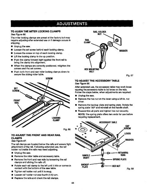
TOAUGNTHEMITERLOCKINGCLAMPS<br />
See Figure 66.<br />
The miter lock<strong>in</strong>g clamps are preset at the factory but may<br />
requireadjust<strong>in</strong>gafter extended use or if damage occurs<strong>in</strong><br />
shipp<strong>in</strong>g.<br />
• Unplug the saw.<br />
• Loosen the set screw beh<strong>in</strong>d each lock<strong>in</strong>gclamp.<br />
• Loosen the screw on top of each Iock<strong>in</strong>gclamp.<br />
• Uft the locldng clamp to the up position,<br />
• Push the clamp forward tight aga<strong>in</strong>st the front railto<br />
br<strong>in</strong>gthe c_p <strong>in</strong>to aiigr_'_ent.<br />
• When the clamps are correctlypositioned,retightenthe<br />
scows and the setscrews.<br />
• Push both front and rearmiter lock<strong>in</strong>gclampsdown to<br />
securethe s|id<strong>in</strong>gmiter table.<br />
SCREW<br />
TO ADJUST THE FRONT AND REAR RAIL<br />
CLAMPS<br />
See Rgure 67.<br />
Fig. 66<br />
The rail crampsate located below the raUsand ensure tight<br />
attachment of the rail.Followrngextended use, the rail<br />
holder nut<strong>in</strong>sidethe rails may need adjust<strong>in</strong>g.<br />
• Unplug the saw.<br />
• Remove the miter table and accessorytabla.<br />
• Remove the _ont emdrear rails by loosen<strong>in</strong>gthe rail<br />
crampsand dld<strong>in</strong>g the rai_soff.<br />
• Rotate each rail clamp to the {sft unti{it hits orcomes <strong>in</strong><br />
correct with the bo'_om ot the saw table.<br />
• Tighten raitholder nut untilit is snug.<br />
• Loosen rail holder nutone-fourth (1/4) turn.<br />
• Replace the rails and check the rail clamps.<br />
44<br />
RAIL<br />
CLAMP<br />
RAILHOLOER<br />
NUT<br />
HE)(MOUNTING<br />
BOLT<br />
TO ADJUST THE ACCESSORY <strong>TABLE</strong><br />
See Rgure 68.<br />
WASHER<br />
Fig. 67<br />
After extended use, the acce..-_, tab/emay workloose<br />
caus(_ th_ accessorytable to be {oos_ o_ the ra'_s.<br />
Foi(owthe steps below,when adjustmentsare required:<br />
• Unplugthe saw.<br />
• Removethe hex nut on the leverus<strong>in</strong>gs 3/8 <strong>in</strong>. nut<br />
driver.<br />
• Removet_e backup p{ateand spr<strong>in</strong>g plate. Rotate the<br />
spr<strong>in</strong>gplate 180° and re<strong>in</strong>stallon the handleshaft.<br />
• Reassemble allparts end tightenhex nut securely.<br />
NOTE; The spr<strong>in</strong>g plate offerstwo endsfor use before<br />
re_[uir<strong>in</strong>greplacement.<br />
ACCESSORY<strong>TABLE</strong><br />
LEVER<br />
HAl RING<br />
_"IAFT<br />
SPRINGPLATE<br />
BACKUP<br />
PLATE HEXNUT<br />
F_.68