Pike Technologies Comprehensive Catalog of FTIR ... - Madatec
Pike Technologies Comprehensive Catalog of FTIR ... - Madatec
Pike Technologies Comprehensive Catalog of FTIR ... - Madatec

Create successful ePaper yourself
Turn your PDF publications into a flip-book with our unique Google optimized e-Paper software.
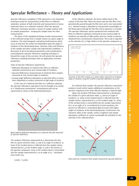
Specular Reflectance – Theory and Applications<br />
Specular reflectance sampling in <strong>FTIR</strong> represents a very important<br />
technique useful for measurement <strong>of</strong> thin films on reflective<br />
substrates, analysis <strong>of</strong> bulk materials and measurement <strong>of</strong> monomolecular<br />
layers on a substrate material. Often the specular<br />
reflectance technique provides a means <strong>of</strong> sample analysis with<br />
no sample preparation – keeping the sample intact for other<br />
measurements.<br />
The basics <strong>of</strong> the sampling technique involve measurement<br />
<strong>of</strong> the reflected energy from a sample surface at a given angle <strong>of</strong><br />
incidence. The electromagnetic and physical phenomena which<br />
occur at and near the surface are dependent upon the angle <strong>of</strong><br />
incidence <strong>of</strong> the illuminating beam, refractive index and thickness<br />
<strong>of</strong> the sample and other sample and experimental conditions. A<br />
discussion <strong>of</strong> all <strong>of</strong> the physical parameters and considerations<br />
surrounding the specular reflectance sampling technique is<br />
beyond the scope <strong>of</strong> this overview. We will present the specular<br />
reflectance sampling technique from an applications oriented<br />
perspective.<br />
Types <strong>of</strong> specular reflectance experiments<br />
• Reflection-Absorption <strong>of</strong> relatively thin films on reflective<br />
substrates measured at near normal angle <strong>of</strong> incidence<br />
• Specular Reflectance measurements <strong>of</strong> relatively thick samples<br />
measured at near normal angle <strong>of</strong> incidence<br />
• Grazing Angle Reflection-Absorption <strong>of</strong> ultra-thin films or monolayers<br />
deposited on surfaces measured at high angle <strong>of</strong> incidence<br />
In the case <strong>of</strong> a relatively thin film on a reflective substrate,<br />
the specular reflectance experiment may be thought <strong>of</strong> as similar<br />
to a “double-pass transmission” measurement and can be<br />
represented as shown in the following illustration;<br />
At the reflective substrate, the beam reflects back to the<br />
surface <strong>of</strong> the thin film. When the beam exits the thin film it has<br />
geometrically passed through the film twice and is now represented<br />
as I A . Infrared energy is absorbed at characteristic wavelengths as<br />
this beam passes through the thin film and its spectrum is recorded.<br />
The specular reflectance spectra produced from relatively thin<br />
films on reflective substrates measured at near-normal angle <strong>of</strong><br />
incidence are typically <strong>of</strong> high quality and very similar to spectra<br />
obtained from a transmission measurement. This result is expected<br />
as the intensity <strong>of</strong> I A is high relative to the specular component, I R .<br />
Spectrum <strong>of</strong> thin film coating on a metal surface measured at 30 degrees<br />
angle <strong>of</strong> incidence using the VeeMAX II specular reflectance accessory<br />
For relatively thick samples, the specular reflectance experiment<br />
produces results which require additional considerations as the<br />
specular component <strong>of</strong> the total reflected radiation is relatively high.<br />
Again, the incident <strong>FTIR</strong> beam represented by I 0 illuminates<br />
the sample <strong>of</strong> a given refractive index, n 2 and at an angle <strong>of</strong><br />
incidence, θ 1 . Some <strong>of</strong> the incident beam is reflected from the<br />
sample surface, represented by I R at the incident angle, θ 1 . Some<br />
<strong>of</strong> the incident beam is transmitted into the sample represented<br />
by I T at an angle <strong>of</strong> θ 2 . As predicted by Fresnel equations, the<br />
percent <strong>of</strong> reflected vs. transmitted light increases with higher<br />
angles <strong>of</strong> incidence <strong>of</strong> the illuminating beam. Furthermore, the<br />
refractive index <strong>of</strong> the sample, surface roughness and sample<br />
absorption coefficient at a given wavelength all contribute to the<br />
intensity <strong>of</strong> the reflected beam.<br />
S PECULAR R EFLECTANCE P RODUCTS – T HIN F ILMS AND M ORE<br />
Beam path for Reflection-Absorption <strong>of</strong> a relatively thin film measured<br />
by Specular Reflectance<br />
The incident <strong>FTIR</strong> beam represented by I 0 illuminates the thin<br />
film <strong>of</strong> a given refractive index, n 2 and at an angle <strong>of</strong> incidence, θ 1 .<br />
Some <strong>of</strong> the incident beam is reflected from the sample surface,<br />
represented by I R at the incident angle, θ 1 and is also known as<br />
the specular component. Some <strong>of</strong> the incident beam is transmitted<br />
into the sample represented by I T at an angle <strong>of</strong> θ 2 – calculated<br />
from Snell’s Law.<br />
n 1 sinθ 1 = n 2 sinθ 2<br />
Beam path for a relatively thick sample measured by Specular Reflection<br />
45