Pike Technologies Comprehensive Catalog of FTIR ... - Madatec
Pike Technologies Comprehensive Catalog of FTIR ... - Madatec
Pike Technologies Comprehensive Catalog of FTIR ... - Madatec
You also want an ePaper? Increase the reach of your titles
YUMPU automatically turns print PDFs into web optimized ePapers that Google loves.
P IKE T ECHNOLOGIES WWW. PIKETECH. COM 608-274-2721<br />
A well-designed sphere has the sample close to the sphere<br />
geometry so that the sphere will collect close to the full available<br />
hemispherical reflectance (2π steradians). A window to separate<br />
the sphere and sample may be important in some cases, but it<br />
will place the sample a small distance from the sphere, thereby<br />
somewhat reducing the collected high-angle reflectance. The PIKE<br />
<strong>Technologies</strong> integrating spheres are coated with the highest<br />
possible reflective surface for the desired wavelength region. The<br />
coating <strong>of</strong> the surface <strong>of</strong> the sphere has to be uniform and close<br />
to being a perfect Lambertian scatterer. These characteristics<br />
allow the light falling in the sphere to be uniformly distributed<br />
over the entire surface <strong>of</strong> the sphere. It is also important how<br />
much <strong>of</strong> this light is actually collected on the detector surface.<br />
Sphere Throughput<br />
The throughput <strong>of</strong> the sphere is defined as the ratio <strong>of</strong> the<br />
incoming light impinging on the detector. The closer the sphere<br />
surface is to ideal reflectance, the higher the throughput. The<br />
detector, the sample and the illumination require that a portion<br />
<strong>of</strong> the wall <strong>of</strong> the complete sphere be removed. Smaller cutouts<br />
for beam input and output result in higher energy throughput.<br />
Due to other considerations, such as reduction <strong>of</strong> light scatter<br />
from the edges <strong>of</strong> the sphere cutouts, called ports, these have to<br />
be optimized and cannot be too small.<br />
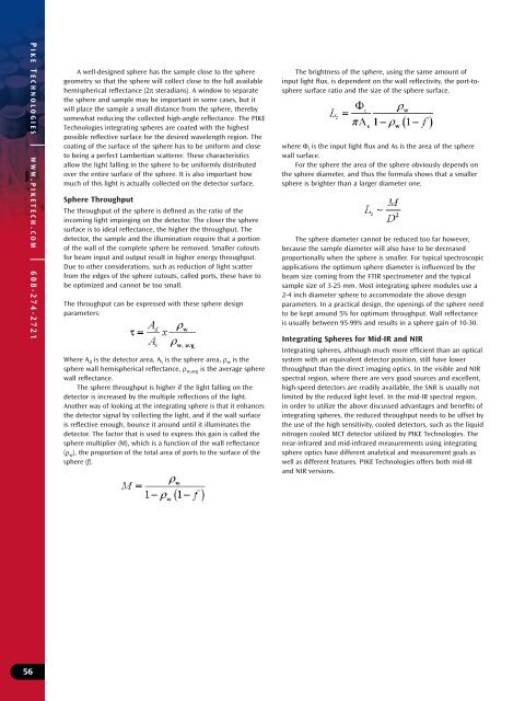
The throughput can be expressed with these sphere design<br />
parameters:<br />
Where A d is the detector area, A s is the sphere area, ρ w is the<br />
sphere wall hemispherical reflectance, ρ w,avg is the average sphere<br />
wall reflectance.<br />
The sphere throughput is higher if the light falling on the<br />
detector is increased by the multiple reflections <strong>of</strong> the light.<br />
Another way <strong>of</strong> looking at the integrating sphere is that it enhances<br />
the detector signal by collecting the light, and if the wall surface<br />
is reflective enough, bounce it around until it illuminates the<br />
detector. The factor that is used to express this gain is called the<br />
sphere multiplier (M), which is a function <strong>of</strong> the wall reflectance<br />
(ρ w ), the proportion <strong>of</strong> the total area <strong>of</strong> ports to the surface <strong>of</strong> the<br />
sphere (f).<br />
The brightness <strong>of</strong> the sphere, using the same amount <strong>of</strong><br />
input light flux, is dependent on the wall reflectivity, the port-tosphere<br />
surface ratio and the size <strong>of</strong> the sphere surface.<br />
where Φ i is the input light flux and As is the area <strong>of</strong> the sphere<br />
wall surface.<br />
For the sphere the area <strong>of</strong> the sphere obviously depends on<br />
the sphere diameter, and thus the formula shows that a smaller<br />
sphere is brighter than a larger diameter one.<br />
The sphere diameter cannot be reduced too far however,<br />
because the sample diameter will also have to be decreased<br />
proportionally when the sphere is smaller. For typical spectroscopic<br />
applications the optimum sphere diameter is influenced by the<br />
beam size coming from the <strong>FTIR</strong> spectrometer and the typical<br />
sample size <strong>of</strong> 3-25 mm. Most integrating sphere modules use a<br />
2-4 inch diameter sphere to accommodate the above design<br />
parameters. In a practical design, the openings <strong>of</strong> the sphere need<br />
to be kept around 5% for optimum throughput. Wall reflectance<br />
is usually between 95-99% and results in a sphere gain <strong>of</strong> 10-30.<br />
Integrating Spheres for Mid-IR and NIR<br />
Integrating spheres, although much more efficient than an optical<br />
system with an equivalent detector position, still have lower<br />
throughput than the direct imaging optics. In the visible and NIR<br />
spectral region, where there are very good sources and excellent,<br />
high-speed detectors are readily available, the SNR is usually not<br />
limited by the reduced light level. In the mid-IR spectral region,<br />
in order to utilize the above discussed advantages and benefits <strong>of</strong><br />
integrating spheres, the reduced throughput needs to be <strong>of</strong>fset by<br />
the use <strong>of</strong> the high sensitivity, cooled detectors, such as the liquid<br />
nitrogen cooled MCT detector utilized by PIKE <strong>Technologies</strong>. The<br />
near-infrared and mid-infrared measurements using integrating<br />
sphere optics have different analytical and measurement goals as<br />
well as different features. PIKE <strong>Technologies</strong> <strong>of</strong>fers both mid-IR<br />
and NIR versions.<br />
56


