Pike Technologies Comprehensive Catalog of FTIR ... - Madatec
Pike Technologies Comprehensive Catalog of FTIR ... - Madatec
Pike Technologies Comprehensive Catalog of FTIR ... - Madatec

Create successful ePaper yourself
Turn your PDF publications into a flip-book with our unique Google optimized e-Paper software.
Integrating Spheres – Introduction and Theory<br />
Measuring Sample Reflectance<br />
Reflectance sampling accessories rely upon a light beam coming<br />
from the spectrometer to be focused upon the sample. In order<br />
to achieve the best signal-to-noise ratio (SNR), the smaller the<br />
focus is, the easier it is to refocus the illuminated sample spot<br />
back onto the detector. In order to measure light reflected at a<br />
larger angle, optical designs will allow only a small area <strong>of</strong> the<br />
sample to be projected onto the detector. This arrangement<br />
serves well if the sample is microscopically homogeneous, but<br />
will result in a larger sample position error. When the sample is<br />
moved, the focused beam will see a different portion <strong>of</strong> the sample<br />
resulting in measurement-to-measurement differences. This is<br />
called insertion error because the spectrum will be slightly<br />
different each time the sample is inserted.<br />
Some industrial or natural samples are inhomogeneous<br />
either because they are mixtures <strong>of</strong> different substances or<br />
because they have a particle size comparable to the probing<br />
beam diameter. Clearly, if the probing beam could be larger and<br />
the reflected light could all be collected, a more representative<br />
spectrum could be measured.<br />
Some other samples develop a directional scattering. For<br />
example, fibers wound on a mandrel are highly oriented, not just<br />
macroscopically as parallel, unidirectional filaments, but also in<br />
many cases the molecules <strong>of</strong> the drawn fibers are oriented within<br />
the fiber itself. Such a sample, when placed in a reflectance<br />
accessory will generate different results depending on the angle<br />
from which the detector is “viewing” the sample. When the overall<br />
reflectance needs to be measured reproducibly, for example to<br />
measure the concentration <strong>of</strong> a minor ingredient in the sample,<br />
only isotropic optical systems, insensitive to such directionalities<br />
could be utilized.<br />
Furthermore, in some cases, not just the reflectance in a<br />
small solid angle but the reflectance in all angles is sought. Most<br />
reflectance accessories measure at fixed or variable angles, narrower<br />
or wider collection angles, but there is a need for a device<br />
that uniformly collects all reflected light from a sample. In other<br />
words it measures the total reflectance <strong>of</strong> the sample.<br />
Therefore the main reasons for using integrating spheres for<br />
the measurement <strong>of</strong> sample reflectance are the following:<br />
• Efficient measurement <strong>of</strong> combined diffuse and specular<br />
reflectance<br />
• Uniform detection <strong>of</strong> reflectance even when sample is<br />
inhomogeneous<br />
• Isotropic detection <strong>of</strong> reflectance even on samples that reflect<br />
in preferred directions<br />
• Reduction <strong>of</strong> polarization effects from the illuminating beam<br />
and the sample<br />
• Measurement <strong>of</strong> absolute reflectance (with special<br />
integrating spheres)<br />
All <strong>of</strong> the above concerns are addressed with integrating<br />
sphere based reflectometers.<br />
Integrating Sphere Optics<br />
Integrating spheres are highly reflective enclosures that are<br />
placed in close proximity to the sample, such that the reflected<br />
light enters the sphere, bounces around the highly reflective<br />
diffuse surface <strong>of</strong> the sphere wall and finally impinges upon the<br />
detector – usually part <strong>of</strong> the integrating sphere assembly. The<br />
name, integrating sphere, refers to one <strong>of</strong> the main functions <strong>of</strong><br />
the device, namely that it spatially integrates the light flux, in our<br />
application the light reflected from a sample. In spite <strong>of</strong> the long<br />
history <strong>of</strong> engineering and development <strong>of</strong> the sphere, the applications<br />
and further developments continue to this day. Advances<br />
in the theory, detector and electronics development and most <strong>of</strong><br />
all, new applications, drive the progress.<br />
As the name implies, the main part <strong>of</strong> the device is a sphere<br />
with a very highly reflecting inner surface. The surface should<br />
approach the ideal Lambertian scatterer, which means that the<br />
light falling on the surface is evenly scattered in all directions and<br />
the scattered light intensity is proportional to the cosine <strong>of</strong> the<br />
angle <strong>of</strong> observation.<br />
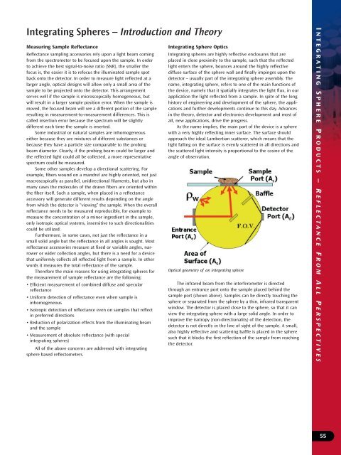
Optical geometry <strong>of</strong> an integrating sphere<br />
The infrared beam from the interferometer is directed<br />
through an entrance port onto the sample placed behind the<br />
sample port (shown above). Samples can be directly touching the<br />
sphere or separated from the sphere by a thin, infrared transparent<br />
window. The detector is placed close to the sphere, so that it can<br />
view the integrating sphere with a large solid angle. In order to<br />
improve the isotropy (non-directionality) <strong>of</strong> the detection, the<br />
detector is not directly in the line <strong>of</strong> sight <strong>of</strong> the sample. A small,<br />
also highly reflective and scattering baffle is placed in the sphere<br />
such that it blocks the first reflection <strong>of</strong> the sample from reaching<br />
the detector.<br />
I NTEGRATING S PHERE P RODUCTS – R EFLECTANCE F ROM A LL P ERSPECTIVES<br />
55