Pike Technologies Comprehensive Catalog of FTIR ... - Madatec
Pike Technologies Comprehensive Catalog of FTIR ... - Madatec
Pike Technologies Comprehensive Catalog of FTIR ... - Madatec

You also want an ePaper? Increase the reach of your titles
YUMPU automatically turns print PDFs into web optimized ePapers that Google loves.
Infrared Polarizers – Theory and Applications<br />
Polarizers are valuable tools used for spectroscopic analysis <strong>of</strong><br />
sample orientation and for measuring thin films on reflective<br />
surfaces. This overview presents basic polarization theory and<br />
highlights some useful polarization applications.<br />
For the purposes <strong>of</strong> discussing polarizers, light is considered<br />
an electric field with a magnitude oscillating in time. Light<br />
propagating along the z axis can be described as a combination<br />
<strong>of</strong> electric vectors in x and y axis. Linearly polarized light may be<br />
thought <strong>of</strong> as consisting <strong>of</strong> an x and a y component with different<br />
relative magnitudes. For example, if the y component is close to<br />
zero, the light is considered fully polarized in the x direction.<br />
Polarizers are devices that split unpolarized light into two<br />
orthogonal components; one <strong>of</strong> the linearly polarized components<br />
is transmitted, the other is reflected, redirected or absorbed. The<br />
most important features <strong>of</strong> a good polarizer are brightness,<br />
contrast and durability. Brightness and contrast can be described<br />
by two main parameters; K 1 and K 2 .<br />
K 1 = Transmission efficiency for normally incident polarized<br />
light whose electric field vector is perpendicular to the<br />
wire direction.<br />
K 2 = Transmission efficiency for normally incident polarized<br />
light whose electric field vector is parallel to the wire<br />
direction.<br />
For a ‘perfect polarizer’ K 1 = 1, which means full transmission<br />
<strong>of</strong> polarized light whose electric field vector is in the preferred<br />
direction and K 2 = 0, which means complete blockage <strong>of</strong> a beam<br />
<strong>of</strong> polarized light whose electric vector is perpendicular to the<br />
former. Other measures <strong>of</strong> performance deduced from K 1 and K 2 are<br />
Degree <strong>of</strong> polarization =<br />
Extinction Ratio =<br />
K1<br />
2K<br />
( K1−<br />
K2)<br />
( K + K )<br />
1 2<br />
Principal transmittance ratio or contrast =<br />
2<br />
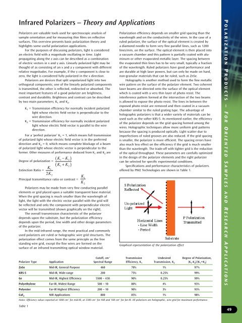
Polarizers may be made from very fine conducting parallel<br />
elements or grid placed upon a suitable transparent base material.<br />
When the grid spacing is much smaller than the wavelength <strong>of</strong><br />
light, the light with the electric vector parallel with the grid will<br />
be reflected and only the component with perpendicular electric<br />
vector will be transmitted (shown graphically on the right).<br />
The overall transmission characteristic <strong>of</strong> the polarizer<br />
depends upon the substrate, but the polarization efficiency<br />
depends upon the period, line width and other design parameters<br />
<strong>of</strong> the polarizer.<br />
In the mid-infrared range, the most practical and commonly<br />
used polarizers are ruled or holographic wire grid structures. The<br />
polarization effect comes from the same principle as the free<br />
standing wire grid, except the fine wires are formed on the<br />
surface <strong>of</strong> an infrared transmitting optical window material.<br />
K<br />
K<br />
1<br />
2<br />
Polarization efficiency depends on smaller grid spacing than the<br />
wavelength and on the conductivity <strong>of</strong> the wires. In the case <strong>of</strong> a<br />
ruled polarizer, the surface <strong>of</strong> the optical element is created by<br />
a diamond needle to form very fine parallel lines, such as 1200<br />
lines/mm, on the surface. The optical element is then placed into<br />
a vacuum chamber and this pattern is partially coated with aluminum<br />
or other evaporated metallic layer. The spacing between<br />
the evaporated thin lines has to be very small, typically a fraction<br />
<strong>of</strong> the wavelength. Ruled polarizers have good performance and<br />
are durable at high laser powers, but can only be made on hard,<br />
non-granular materials that can be ruled, such as ZnSe.<br />
Holography is another method used to form the fine metallic<br />
wire pattern on the surface <strong>of</strong> the polarizer element. Two coherent<br />
laser beams are directed onto the surface <strong>of</strong> the optical element<br />
which is coated with a very thin layer <strong>of</strong> photo resist. The<br />
interference pattern formed at the intersection <strong>of</strong> the two beams<br />
is allowed to expose the photo resist. The lines in between the<br />
exposed photo resist are removed and then coated in a vacuum<br />
chamber similar to the ruled grating type. The advantage <strong>of</strong><br />
holographic polarizers is that a wider variety <strong>of</strong> materials can be<br />
used such as the s<strong>of</strong>ter KRS-5. As mentioned earlier, the efficiency<br />
<strong>of</strong> the polarizer depends on the grid spacing formed among the<br />
wires. Holographic techniques allow more uniform grid patterns<br />
because the spacing is produced optically. Light scatter due to<br />
imperfections <strong>of</strong> ruled grooves are also reduced. If the grid spacing<br />
is smaller, the polarizer is more efficient. The spacing errors have<br />
also much less effect on the efficiency if the grid is much smaller<br />
than the wavelength. The trade-<strong>of</strong>f with tighter grid is the reduction<br />
<strong>of</strong> the optical throughput. These parameters are carefully optimized<br />
in the design <strong>of</strong> the polarizer elements and the right polarizer<br />
can be selected for specific experimental conditions.<br />
Specifications and performance characteristics <strong>of</strong> polarizers<br />
<strong>of</strong>fered by PIKE <strong>Technologies</strong> are shown in Table 1.<br />
Cut<strong>of</strong>f, cm -1 Transmission Undesired Degree <strong>of</strong> Polarization,<br />
Polarizer Type Application Spectral Range Efficiency, K 1 Transmission, K 2 (K 1 -K 2 )/(K 1 +K 2 )<br />
ZnSe Mid-IR, General Purpose 460 70% 1% 97%<br />
KRS-5 Mid-IR, Wide-range 200 75% 0.25% 99%<br />
Ge Mid-IR, Highest Efficiency 5500 – 430 90% 0.25% 99%<br />
Polyethylene Far-IR, Widest Range 500 – 10 80% 4% 93%<br />
Polyester Far-IR Highest Efficiency 200 – 10 90% 3% 93%<br />
CaF 2 NIR Applications 800 85% 1% 98%<br />
Notes: Efficiency values reported at 1000 cm -1 for mid-IR, at 3300 cm -1 for NIR and 100 cm -1 for far-IR. All polarizers are holographic, wire grid for maximum performance.<br />
Table 1<br />
Graphical representation <strong>of</strong> the polarization effect<br />
P OLARIZATION P RODUCTS – F OR O RIENTED S AMPLES AND R ESEARCH A PPLICATIONS<br />
49