R3400 Technical data - Rendamax
R3400 Technical data - Rendamax
R3400 Technical data - Rendamax

You also want an ePaper? Increase the reach of your titles
YUMPU automatically turns print PDFs into web optimized ePapers that Google loves.
<strong>Rendamax</strong><br />
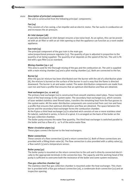
2.2.1 Description of principal components<br />
The unit is constructed from the following principal compo nents:<br />
Fan [24]<br />
This consists of a fan casing, a fan impeller and an electric motor. The fan sucks in combustion air<br />
and increases the air pressure.<br />
Air inlet damper [28]<br />
A specially developed air inlet damper ensures a low noise level. As an option, this can be provided<br />
with an air filter or with an air inlet opening so that the appliance can function as a room sealed<br />
appliance.<br />
Gas train [13]<br />
The principal component of the gas train is the main gas<br />
valve/proportional pressure regulator [23]. The quantity of gas is adjusted in proportion to the<br />
quantity of air being supplied. The quantity of air depends on the speed of the fan. The unit is fitted<br />
with a gas filter [11] as standard.<br />
Mixing chamber [29 + 31]<br />
This area is used for the thorough mixing of the gas and the combustion air. The unit is supplied<br />
with a main mixing cham ber [29] and a pilot mixing chamber [31]. Both are connected to the fan.<br />
Burner [9]<br />
After the gas/air mixture has been distributed over the burner with the aid of a distribution plate<br />
[8], the mixture is burned on the surface of the burner in such a way that the flame is di rected<br />
downward. The burner is air and water cooled. The water distribution components are made from<br />
cast iron and have a profile that ensures that an optimum distribution and flow are obtained.<br />
Heat exchangers [10, 12 and 17]<br />
The primary heat exchanger [10] is constructed from smooth stainless steel tubes. These transfer<br />
most of the heat energy to the system water. The secondary heat exchanger [12], which consists<br />
of laser welded stainless steel finned tubes, transfers the remaining heat from the flue gasses to<br />
the system water. All the water distribution components are constructed from cast iron and have<br />
a profile that ensures that optimum distribution and flow are obtained. The space between the<br />
burner and the secondary heat exchanger forms the combustion chamber.<br />
At the R3600 a third heat exchanger [17] is attached wich consists of one or more stainless steel<br />
fin tube(s), switched in series, in form of a spiral. It is arranged on the back of the boiler on the<br />
flue gas collection chamber.<br />
The boiler pump ensures the water flow quantity. The third heat exchanger is switched parallel to<br />
the boiler and has a flow of 5 - 10 % of the entire water flow.<br />
Water circulation pipes [15]<br />
These pipes connect the burner to the heat exchangers.<br />
Water connections<br />
These consist of a flow connection [5] and a return connection [1]. Both of these connections are<br />
provided with a filling/drain valve [6]. The flow connection is also provided with a safety valve [4],<br />
a flow switch [3] and a temperature sensor.<br />
Boiler pump [32]<br />
The boiler pump is mounted on the return connection to the unit and is directly connected electrically<br />
to the appropriate termi nals in the connection box. The capacity and the working head of the<br />
pump is sufficient to overcome both the resistance of the boiler and some system resistance.<br />
Flue gas collection chamber [19]<br />
The stainless steel flue gas collection chamber is mounted under the heat exchanger. This chamber<br />
is provided with a flue gas exhaust connection [16], a condensate drain connection [22] and an<br />
inspection opening.<br />
Doc890/3456CV02B 15