R3400 Technical data - Rendamax
R3400 Technical data - Rendamax
R3400 Technical data - Rendamax

Create successful ePaper yourself
Turn your PDF publications into a flip-book with our unique Google optimized e-Paper software.
<strong>Rendamax</strong><br />
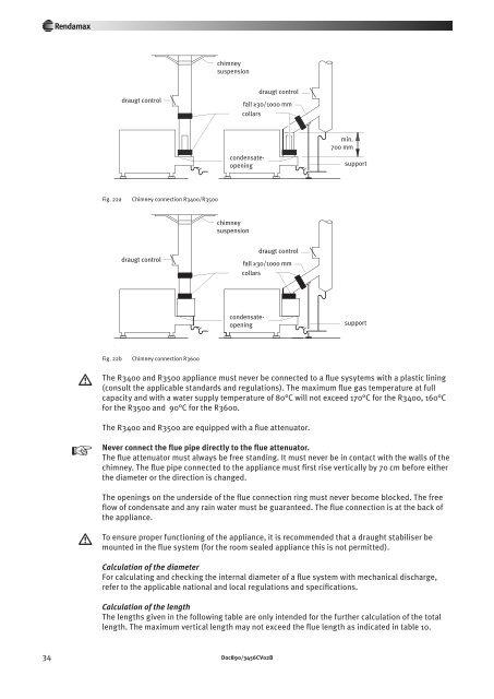
chimney<br />
suspension<br />
draugt control<br />
draugt control<br />
fall ≥30/1000 mm<br />
collars<br />
min.<br />
700 mm<br />
support<br />
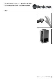
Fig. 22a<br />
Chimney connection <strong>R3400</strong>/R3500<br />
chimney<br />
suspension<br />
draugt control<br />
draugt control<br />
fall ≥30/1000 mm<br />
collars<br />
condensateopening<br />
condensateopening<br />
support<br />
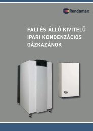
Fig. 22b<br />
Chimney connection R3600<br />
w<br />
The <strong>R3400</strong> and R3500 appliance must never be connected to a flue sysytems with a plastic lining<br />
(consult the applicable stand ards and regulations). The maximum flue gas temperature at full<br />
capacity and with a water supply temperature of 80°C will not exceed 170°C for the <strong>R3400</strong>, 160°C<br />
for the R3500 and 90°C for the R3600.<br />
The <strong>R3400</strong> and R3500 are equipped with a flue attenuator.<br />
y<br />
Never connect the flue pipe directly to the flue attenuator.<br />
The flue attenuator must always be free standing. It must never be in contact with the walls of the<br />
chimney. The flue pipe con nected to the appliance must first rise vertically by 70 cm before either<br />
the diameter or the direction is changed.<br />
The openings on the underside of the flue connection ring must never become blocked. The free<br />
flow of condensate and any rain water must be guaranteed. The flue connection is at the back of<br />
the appliance.<br />
w<br />
To ensure proper functioning of the appliance, it is recom mended that a draught stabiliser be<br />
mounted in the flue system (for the room sealed appliance this is not permitted).<br />
Calculation of the diameter<br />
For calculating and checking the internal diameter of a flue system with mechanical discharge,<br />
refer to the applicable national and local regulations and specifications.<br />
Calculation of the length<br />
The lengths given in the following table are only intended for the further calculation of the total<br />
length. The maximum vertical length may not exceed the flue length as indicated in table 10.<br />
34 Doc890/3456CV02B