R3400 Technical data - Rendamax
R3400 Technical data - Rendamax
R3400 Technical data - Rendamax

Create successful ePaper yourself
Turn your PDF publications into a flip-book with our unique Google optimized e-Paper software.
<strong>Rendamax</strong><br />
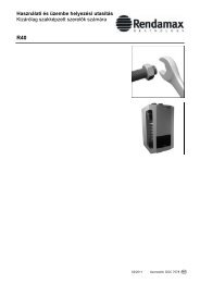
Type ∆T 20 K Pump <strong>data</strong><br />
Nominal<br />
flow<br />
rate<br />
Boilerresistance<br />
Grundfos<br />
Pump type<br />
Pump<br />
speed<br />
Head<br />
at<br />
Qnom.<br />
Available<br />
head at<br />
Qnom.<br />
Max.*<br />
power<br />
consumption<br />
m 3 /h kPa kPa kPa W<br />
R3401 28.54 46 UPS 65-120F 3 77 31 1.15<br />
R3402 31.63 53 UPS 65-120F 3 69 16 1.15<br />
R3403 37.00 36 UPS 65-120F 3 54 18 1.15<br />
R3404 41.84 43 UPS 80-120F 3 70 27 1.50<br />
R3405 46.75 50 UPS 80-120F 3 62 12 1.50<br />
R3406 51.60 58 LM 80-160/162 - 70 12 1.50<br />
R3501 26.36 37 UPS 65-120F 3 80 43 1.15<br />
R3502 30.83 25 UPS 65-120F 3 72 47 1.15<br />
R3503 34.87 30 UPS 65-120F 3 60 30 1.15<br />
R3504 38.96 35 UPS 80-120F 3 75 40 1.50<br />
R3505 43.00 40 UPS 80-120F 3 68 28 1.50<br />
R3601 26.36 37 UPS 65-120F 3 80 43 1.15<br />
R3602 30.83 25 UPS 65-120F 3 72 47 1.15<br />
R3603 34.87 30 UPS 65-120F 3 60 30 1.15<br />
R3604 38.96 35 UPS 80-120F 3 75 40 1.50<br />
R3605 43.00 40 UPS 80-120F 3 68 28 1.50<br />
Table 12<br />
Water flow rate and pump <strong>data</strong><br />
* The maximum power consumption of the pump is given for pump speed 3. The optimum operating point in relation to<br />
efficiency and minimum power consumption can be determined from the related pump curve.<br />
The primary pump has been sized to have an optimum duty when ∆T = 20 K. When running at ∆T’s<br />
less than 20 K the pump size should be checked to ensure suitability.<br />
The water flow rate can be adjusted with the aid of the built-in 3-speed pump control. The water<br />
flow rate can be measured by making a ∆P measurement via the filling and drainage valve in the<br />
supply and return pipe of the unit. The measured head can be compared with the boiler resistance<br />
(table 12). At full capacity the water flow rate can be very accurately compared with the ∆T, measured<br />
acros the flow and return of the boiler.<br />
The unit has a standard pump control. When the boiler is en abled, the pump is switched on. When<br />
the enable signal is removed, the pump will continue to run for several minutes. This run on time<br />
is adjustable. The standard time is two minutes.<br />
y<br />
When the system includes air heaters (ventilation, air treat ment), it is usually desirable to have a<br />
small ∆T over these components. Because of this, the quantity of water flowing through the total<br />
secondary circuit is usually greater than that flowing through the boiler units.<br />
The low velocity header must be dimensioned such that the water speed does not exceed 0.5 m/s.<br />
In this case the diameter of the header must be calculated for the water volume flowing through<br />
the secondary circuit. When the water volume flowing through the secondary circuit is great er<br />
than that flowing through the primary circuit, a mixed temper ature will exist which is lower than<br />
the desired temperature of the supply from the appliance. The regulation system reacts to this<br />
and opens the control devices (valves, etc.). Usually the supply temperature from the boiler(s)<br />
must be adjusted to obtain the desired temperature in the connected circuits.<br />
38 Doc890/3456CV02B