
Create successful ePaper yourself
Turn your PDF publications into a flip-book with our unique Google optimized e-Paper software.
AW5784 Rev. 1.0 (US)<br />
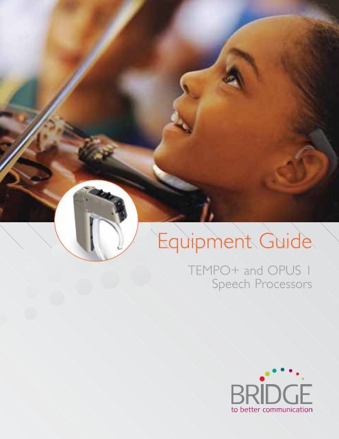
<strong>Equipment</strong> <strong>Guide</strong><br />
TEMPO+ and OPUS 1<br />
Speech Processors
i<br />
The OPUS 1 speech processor has<br />
a “Fine Structure” symbol etched<br />
on its surface. The TEMPO+ speech<br />
processor does not.<br />
INTROdUCTION<br />
If you’re working with a child who listens with a MEd-EL<br />
Cochlear Implant System, you’ll soon want assistance in<br />
how to handle the equipment, how to verify that the<br />
device is working properly, and what to do if the system<br />
isn’t working properly.<br />
This guide is designed to help you become confident in handling and assembling<br />
the parts of the TEMPO+ and OPUS 1 speech processors, understanding all of<br />
the available wearing options, and objectively verifying that the device is working<br />
properly. It will provide step-by-step instructions to help identify and solve any<br />
problems that may arise, and will assist you in understanding how to care for<br />
the system properly.<br />
The OPUS 1 and TEMPO+ speech processors look the same. You can<br />
differentiate a TEMPO+ from an OPUS 1 speech processor easily: the OPUS 1 has<br />
a small music note etched on its surface, near the switches marked x-y-z and 1-2-3.<br />
The OPUS 1 Speech Processor contains a microchip that has the capability to<br />
implement newer sound coding technology (although this new technology may<br />
or may not be activated for a particular child). Techniques for managing and<br />
troubleshooting both processors discussed in this guide are the same.<br />
Although the audiologist or the child’s implant center typically handles advanced<br />
troubleshooting, many classroom teachers and therapists find that minor<br />
problems can be quickly and easily managed without disrupting the day’s learning<br />
plan if they are comfortable troubleshooting and handling the equipment. Please<br />
keep this guide in a handy place, and refer to it whenever problems may arise.<br />
<strong>Equipment</strong> <strong>Guide</strong>: TEMPO+ and OPUS 1 Speech Processors, Version 2.0.<br />
©2009 MEd-EL CORPORATION, NA. All rights reserved.<br />
TABLE OF CONTENTS<br />
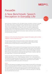
NOTE:<br />
This <strong>Guide</strong> deals with the TEMPO+<br />
and OPUS 1 speech processors.<br />
If you are working with an OPUS 2<br />
processor (pictured above), please<br />
refer to the <strong>Equipment</strong> <strong>Guide</strong> for OPUS 2.<br />
1 Getting to know the TEMPO+ and OPUS 1<br />
speech processors ............................................................................2<br />
Parts of the system ..................................................................2<br />
Wearing options.......................................................................11<br />
BabyBTE (also called the ‘activity pack’)............. 14<br />
Children’s battery pack .......................................................15<br />
Angled battery pack .............................................................16<br />
Straight battery pack ............................................................ 17<br />
Special considerations for small children ................. 17<br />
Remote (rechargeable) battery pack .........................18<br />
daCapo Rechargeable Battery System .................... 19<br />
2 Is it working? A troubleshooting primer ......................20<br />
daily listening checks ............................................................20<br />
Troubleshooting features ...................................................25<br />
A step-by-step troubleshooting guide ......................28<br />
Keeping spare equipment on hand .............................30<br />
What to do if you don’t feel comfortable<br />
with the child’s equipment ...............................................31<br />
A word about warranties..................................................31<br />
3 Caring for the system .................................................................32<br />
Moisture .......................................................................................32<br />
<strong>El</strong>ectrostatic discharge<br />
(ESd or Static <strong>El</strong>ectricity) .................................................33<br />
Sports ............................................................................................35<br />
Metal detectors .......................................................................35<br />
4 Connecting to Accessory Devices ....................................36<br />
When to use accessory devices<br />
such as FM systems ...............................................................36<br />
Mixing options ..........................................................................37<br />
Step by step connection guide ......................................38<br />
Connecting the patch cable .............................................39<br />
The Telemic accessory ........................................................40<br />
Available accessories for<br />
the TEMPO+and OPUS 1 ...............................................41<br />
5 Glossary of terms related to<br />
MEd-EL cochlear implant systems ........................................42<br />
6 MED-EL Milestones ......................................................................53
2<br />
1<br />
GETTING TO KNOW THE TEMPO+ ANd<br />
OPUS 1 SPEECH PROCESSORS<br />
PARTS OF THE SYSTEM<br />
The MEd-EL TEMPO+ and OPUS 1 speech processors consist of four main<br />
parts: a control unit, a battery pack, a coil and a coil cable. The system is<br />
modular, so the parts can be combined in different ways, and the system can be<br />
worn differently from day to day depending on the needs of each particular child.<br />
In addition, each child receives a patient kit that contains a variety of accessories.<br />
Each wearing option will have the following parts:<br />
control unit<br />
earhook<br />
battery pack<br />
coil<br />
coil cable<br />
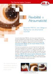
Control unit<br />
The control unit is just like a tiny computer. Inside, an<br />
electronic chip controls the entire system. It can hold several<br />
different programs (also called ‘maps’), which contain the<br />
specific hearing settings for each child. It has controls that can<br />
change the way the system operates:<br />
Program switch :: The program switch (labeled ‘1-2-3’)<br />
allows the user to switch between different<br />
programs. An experienced listener might<br />
have specific programs for different listening<br />
environments. For example, one program might<br />
be used when there is a lot of background noise, and<br />
another might be used for talking on the phone.<br />
Volume switch :: The volume switch (labeled ‘X-Y-Z’)<br />
allows the user to switch between different volumes<br />
for each program. Usually the processor is<br />
programmed so that the ‘X’ setting is loudest,<br />
and the ‘Z’ setting is softest. Please refer to the child’s<br />
implant center for specific information<br />
on how the processor was programmed.<br />
Sensitivity control :: The sensitivity control determines how sensitive the<br />
microphone is at any given time, and in particular, how it handles medium<br />
and loud sounds to be sure that the user is always hearing at<br />
a comfortable level. Generally the sensitivity control is set at the mid-point.<br />
At the mid-point, the red dot should be at approximately 2 or 3 o’clock<br />
when looking directly at the sensitivity control knob (holding<br />
the processor with the volume and program switches facing up). This setting<br />
provides hearing sensitivity at a significant distance without overly amplifying<br />
medium and soft sounds; if the dial is set higher, the system may pick up<br />
sounds from greater distance, but soft sounds may be presented at louder<br />
levels than necessary. Experienced listeners find the sensitivity control to be<br />
useful in customizing their listening experience, but for children, it is typically<br />
recommended to set the dial at mid-point.<br />
Microphone port :: This tiny opening on the front of the processor is where<br />
sound enters the processor. The microphone is most sensitive to sounds<br />
coming from the front, although it is able to pick up sounds from a wide area.<br />
LED indicator :: This small red light indicates a variety of different status and<br />
error conditions. Normally it should only illuminate when the speech<br />
processor is first turned on. If it begins flashing during normal use, please<br />
refer to the table on page 25 for troubleshooting assistance.<br />
NOTE: Because the speech processor settings are specific to one child only,<br />
never switch processors between two different implant users or between<br />
ears for a bilateral user. No two ears have the same program settings!<br />
The use of a processor belonging to another user could result in overstimulation.<br />
Volume switch<br />
Program switch<br />
Sensitivity control<br />
LEd indicator<br />
Microphone port<br />
At the mid-point, the red dot<br />
should be at approximately<br />
2 or 3 o’clock when looking<br />
directly at the sensitivity<br />
control knob<br />
EQUIPMENT GUIdE: TEMPO+ and OPUS 1 SPEECH PROCESSORS<br />
3
GETTING TO KNOW THE SPEECH PROCESSOR<br />
Battery packs<br />
Each battery pack contains the batteries, has an ON/OFF switch, and (for three<br />
of the battery packs) an input for assistive listening devices. The battery packs are<br />
separate from the speech processor. The different wearing options are created by<br />
connecting a given battery pack with the speech processor. Five different battery<br />
packs support six different wearing options. Each wearing option and corresponding<br />
battery pack is described in detail in the next section. For information on changing the<br />
batteries, see the “Batteries” section on page 8.<br />
Coil<br />
The coil is a round disk about the size of two stacked quarters. It is responsible for<br />
sending the electronic code across the skin to the implanted device. The coil contains<br />
some electronics, as well as a magnetic disk. This magnetic disk is attracted to the<br />
magnet in the implanted portion, and thus holds the coil against the skin in the<br />
appropriate position. The magnetic strength inside the disk can be adjusted by the<br />
implant center if necessary. If you notice any signs of skin irritation in the area of the<br />
coil, contact the child’s parents or implant center. When the coil is placed over the<br />
implant site, you should be able to feel the magnetic attraction to the internal device<br />
when the coil is directly over the implant. The coil will only ‘stick’ in the correct place<br />
so that the transmitter and receiver align properly – there is no way to put it in the<br />
wrong location.<br />
Several types of coils are available to meet individual needs – some have stronger<br />
magnets, others have lower power requirements while still others are for special<br />
situations. do not switch coils between children without direction from the cochlear<br />
implant center. The implant audiologist can easily adjust the magnetic strength of the coil.<br />
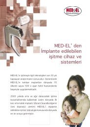
The coil cable<br />
The coil and the speech processor are connected by the coil cable, which carries<br />
information between the two components. The coil cable is available in different<br />
lengths, from 9 cm up to 28 cm (used for the BabyBTE configuration, or to place<br />
the processor on the opposite ear from the implanted ear). There is only one<br />
correct way to insert the cable into the speech processor and the coil (see right).<br />
The coil end of the cable has a particular shape that only fits one way into the coil<br />
– note the shape of the plug and the shape of the plug receptacle on the coil. On<br />
the processor end, special care should be taken to be sure that the cable is inserted<br />
properly, so that the longer pin is inserted into the proper side of the plug.<br />
TIP: One of the coil pins is somewhat longer than the other two. When looking at<br />
the top of the processor (where the program and volume controls are located) with<br />
the microphone pointing away from you, the cable should plug<br />
in so that the largest prong is on the right-hand side.<br />
4 EQUIPMENT GUIdE: TEMPO+ and OPUS 1 SPEECH PROCESSORS<br />
control unit<br />
cable slot<br />
to control unit<br />
to coil<br />
coil<br />
coil cable<br />
5
GETTING TO KNOW THE SPEECH PROCESSOR<br />
Locking U-pin<br />
with fixation nuts<br />
Earhooks for<br />
straight battery pack (L)<br />
and angled battery pack (R)<br />
Earhook for<br />
daCapo battery pack<br />
The earhook has two long metal<br />
pins that slide through tiny holes in<br />
the processor and battery pack.<br />
Connection accessory<br />
For all wearing options, the battery pack (or battery pack cable) is connected to the<br />
speech processor by an earhook (which fits around the back of the ear) or a small<br />
device called a ‘u-pin’. In either case, the connection accessory has two long metal<br />
pins that slide through two tiny holes in the processor and battery pack. These holes<br />
line up when the processor, coil cable, and battery pack are assembled.<br />
There are two main types of standard earhooks: one for the straight battery pack,<br />
and one for the children’s or angled battery pack. The two differ in the direction of<br />
the pins, and each results in slightly different microphone and processor placement<br />
on the ear. A special third earhook type is used to connect the daCapo battery pack<br />
to the control unit.<br />
Earhooks are available in a variety of sizes. Child-sized earhooks are also available in<br />
a ‘locking’ configuration that prevents active toddlers from taking the processor and<br />
battery pack apart. When inserted into the processor/battery pack assembly, the<br />
locking earhook pins protrude slightly from the other side of the processor. There<br />
are two ways to lock the earhook in place: fixation nuts or a safety lock. Two small<br />
metal fixation nuts screw onto the tips of the pins, making it virtually impossible for<br />
most children to remove the earhook. A small jeweler’s screwdriver is helpful when<br />
applying or removing the fixation nuts (a screwdriver is provided in the user kit).<br />
When the fixation nuts are in place, the child is prevented from taking the speech<br />
processor apart or removing the coil cable. Batteries can still be changed without<br />
removing the locking earhook from its secure position.<br />
TIP: If you are having difficulty handling the fixation nuts with the screwdriver, try using a<br />
bit of the soft, moldable material used for hanging posters, or modeling clay, to pick up<br />
and hold the fixation nuts while you are positioning them.<br />
When using the daCapo Rechargeable Battery System, a<br />
safety lock is used to lock the components together. The safety<br />
lock accomplishes the same job as the fixation nuts. It fits over the<br />
protruding pins of the locking (long pin) earhook, and a small black<br />
lever inside the safety lock can be engaged using a pointed object<br />
(a paper clip works nicely). Simply slide the lever as shown in the<br />
photo (at right) to engage or disengage the safety lock.<br />
Fixation bar (optional)<br />
For some wearing options, an additional fixation bar or clip is used to attach a part<br />
of the processor to the child’s clothing. Three of the battery packs (straight, angled,<br />
and children’s battery packs) have two tiny threaded sleeves on the side of the<br />
battery pack, near the serial number.<br />
ON/OFF switch<br />
The power switch is located in the following places:<br />
Angled, children’s and straight battery packs: At the tip of<br />
the battery pack next to the latch that opens the battery<br />
door. It is labeled “ | ” for ON and “ O ” for OFF. Keep in<br />
mind that the children’s battery pack is attached to the end of<br />
its own cable.<br />
Remote battery pack: On the base of the battery pack<br />
labeled “ON/OFF.”<br />
DaCapo battery pack: The battery pack lock functions as the on/off switch.<br />
When the battery pack lock is in the down position (closed), the speech<br />
processor is on.<br />
Battery door<br />
Battery doors have a small latch, and some are designed to discourage children from<br />
tampering with the batteries. To open the battery compartment:<br />
Angled, straight and children’s battery packs:<br />
A small latch at the end of the battery compartment slides to disengage the<br />
battery door. With the thumb of one hand, slide the latch in the direction of the<br />
arrow to release it, and hold it in the open position. Holding the battery pack<br />
between the thumb and index finger of the opposite hand, slide the battery<br />
door towards the end with the latch. The cover should release and open just a<br />
few millimeters. Lift the battery cover completely off.<br />
When replacing the battery door, make sure that all batteries are inserted in<br />
the proper orientation. The flat side of the battery (usually marked “+”) should<br />
be facing outward. do not slide the battery door over all of the batteries or<br />
attempt to snap it into place. Instead, simply place it directly over the batteries,<br />
as if it were almost closed, and gently slide it into place. It is not necessary to<br />
manipulate the latch when closing the battery door cover.<br />
The fixation bar can be used to<br />
secure a safety pin so that the<br />
processor can be attached to a<br />
child’s clothing.<br />
Batteries are inserted with “+”<br />
facing outward.<br />
Place the battery door directly over<br />
the batteries, as if it were almost<br />
closed, and gently slide it into place.<br />
6 EQUIPMENT GUIdE: TEMPO+ and OPUS 1 SPEECH PROCESSORS<br />
ON OFF<br />
Battery<br />
door latch<br />
ON/OFF<br />
switch<br />
7
The children’s battery pack has<br />
a locking battery compartment,<br />
to prevent young children from<br />
opening the battery pack.<br />
Battery<br />
Pack Lock<br />
GETTING TO KNOW THE SPEECH PROCESSOR<br />
daCapo<br />
Battery Pack<br />
Power Pack<br />
Locking battery compartment: The children’s battery pack latch is designed<br />
to be slightly more difficult to open, as it is often used with toddlers and small<br />
children who are more likely to attempt to open the battery pack. It is necessary<br />
to insert a small object, such as a ballpoint pen or the tip of a paper clip, into the<br />
latch in order to slide it in the direction of the arrow.<br />
Remote battery pack: The battery door latch is on the side of the remote<br />
battery pack, labeled “unlock.” Slide the latch downward, holding it down, and<br />
the top of the battery pack will slide open to reveal the battery compartment.<br />
Insert the battery according to the diagram in the compartment. Slide the lid<br />
back into place.<br />
DaCapo battery pack: The battery pack cover on the daCapo is built like<br />
a sleeve, and the daCapo FM-CS battery pack cover also includes input for<br />
assistive listening devices. The battery pack lock functions as the on/off switch.<br />
Flip the battery pack lock up (this turns the processor off), and slide the entire<br />
battery pack cover off the battery pack.<br />
Batteries<br />
MEd-EL cochlear implant systems have a patented power-efficient design that<br />
supports long battery life averaging 3-5 days using three size 675 high-powered<br />
hearing aid batteries. Using the DaCapo ear-level rechargeable battery pack, users<br />
can expect an average of 10-12 hours. Another alternative is the Remote Battery<br />
Pack which averages 1.5 days for a rechargeable AA and 2-3 days for an alkaline AA<br />
battery. Battery life is not dramatically affected by individual map settings, so all users<br />
are assured of being able to enjoy long battery life.<br />
Note: Used batteries should be disposed of according to local regulations. Generally,<br />
it is best not to dispose of batteries with other garbage, as they can contaminate the<br />
environment. Batteries are toxic; if a child swallows a battery, call the nearest poison<br />
control center immediately. It is advisable to remove batteries from the battery pack<br />
if it will be stored for a long period of time.<br />
Button batteries (size 675 HP)<br />
For children using the straight, angled, children’s or BabyBTE wearing options,<br />
high power hearing aid batteries, size 675, are required. It is critical that the<br />
batteries are labeled “high power,” as high power batteries tend to provide<br />
more consistent power over a long period of time. Some newer battery brands<br />
are labeled “ultra” or “extra” instead of “high power.” MEd-EL is continually<br />
evaluating battery brands. Please contact the implant center or MEd-EL for<br />
recommendations of specific battery brands.<br />
Most 675 hearing aid batteries are of the “zinc-air” variety. The power source<br />
is activated by the influx of air through tiny holes on the flat side of the battery.<br />
These batteries have a peel-off sticker that covers the holes until it is time to<br />
use the battery. When the sticker is removed, the batteries are activated and<br />
their useful lifetime begins. Zinc air batteries have a long shelf life as long as the<br />
sticker is intact. Once the sticker is removed, it must be used and cannot be<br />
deactivated (i.e., replacing the sticker will not conserve its useful lifetime or stop<br />
it from discharging).<br />
8 EQUIPMENT GUIdE: TEMPO+ and OPUS 1 SPEECH PROCESSORS<br />
AA batteries<br />
The remote (rechargeable) battery pack utilizes one AA battery. The remote<br />
battery pack uses one AA-size battery, either the rechargeable NiMH or nonrechargeable<br />
alkaline type. Each child receives 3 NiMH rechargeable batteries<br />
and a charger in the user kit. These batteries have a life of approximately 1000<br />
charges each, and a charge should last 1 to 1.5 days. When the rechargeable<br />
batteries have reached the end of their useful lifetime, they can be replaced<br />
through MEd-EL. Some families purchase rechargeable batteries locally. MEd-EL<br />
cannot vouch for the quality of these batteries, but does not discourage families<br />
from trying other brands if desired. Regular alkaline AA batteries can also be<br />
used and should last 2-3 days. Alkaline (non-rechargeable) batteries must<br />
NEVER be placed in the battery charger.<br />
DaCapo PowerPack<br />
To replace the daCapo PowerPack (see image on previous page), you will need<br />
to have a fully charged replacement PowerPack on hand. In the event that you<br />
do not have access to a replacement PowerPack, any of the other battery pack<br />
options described in this guide may be used interchangeably.<br />
A handy way to remove the used<br />
675 batteries from the processor<br />
is to place the flat side of the<br />
coil against the open battery<br />
compartment. The magnet<br />
inside the coil will attract the<br />
batteries, removing them from the<br />
compartment.<br />
9
1<br />
2<br />
GETTING TO KNOW THE SPEECH PROCESSOR<br />
3<br />
Changing the batteries<br />
All battery packs have a small latch mechanism that makes the battery door tamper<br />
resistant (see page 7 for instructions on opening the battery compartment and<br />
removing the batteries). For battery packs using size 675 batteries, be sure the flat<br />
side of the battery (+) is facing you before closing the battery door.<br />
NOTE: When changing the batteries, be sure to turn the processor off and back on<br />
again with fresh batteries in place. If the processor is not reset, the LEd will continue<br />
to flash as if the battery power were low.<br />
Changing the DaCapo rechargeable PowerPack<br />
1 Open the battery pack lock to switch the processor off.<br />
2 Slide the battery pack cover off the daCapo Frame.<br />
3 Remove the small white PowerPack from the battery frame.<br />
4 Add a fresh, fully charged PowerPack.<br />
5 Slide the battery pack cover over the daCapo Frame and<br />
close the battery pack lock to switch the processor on.<br />
6 The battery pack does not need to be disconnected to<br />
change the PowerPack.<br />
For more information on the daCapo Rechargeable System, see page 19.<br />
WEARING OPTIONS<br />
Ear level processors provide a compelling sense of freedom for parents and small<br />
children not to be encumbered by a large box worn on the belt or in a harness.<br />
The various wearing options provide the opportunity to wear the system in ways<br />
that are more secure to the body than the average ear-level system. The wearing<br />
options also allow the child to grow into a traditional ear-level placement as time<br />
and maturity permit, while taking advantage of all of the features of the advanced<br />
processing capability of the system.<br />
In choosing a wearing option, the parent will probably consider factors such as:<br />
:: Will the processor be likely to fall off if the child is active?<br />
:: Will the child attempt to remove the batteries or change the controls?<br />
:: do we want all, part or none of the processor on the child’s ear?<br />
:: Is sweating or moisture a problem?<br />
:: do we prefer to use disposable or rechargeable batteries?<br />
:: do we plan to use assistive listening devices?<br />
It is important to remember that the speech processor consists of one control unit, with<br />
five different battery packs, that can be combined for six different wearing options:<br />
:: Angled battery pack – all-at-the-ear configuration with direct input for<br />
assistive listening devices<br />
:: Straight battery pack – BabyBTE securely placed on the clothing or<br />
straight configuration worn at the ear<br />
:: Children’s battery pack – microphone placement at the ear with the added<br />
security of the battery pack attached to the clothing<br />
:: Remote (rechargeable) battery pack – low-cost alternative with direct<br />
input for assistive listening devices<br />
:: DaCapo Rechargeable Battery System - combines the cost savings of a<br />
rechargeable battery with the convenience of an ear-level placement and<br />
direct input for assistive listening devices.<br />
The five battery packs can produce six different wearing options to facilitate<br />
wearing the system comfortably and securely regardless of age or activity level.<br />
Each wearing option and its assembly is described in detail on the next page.<br />
THE WEARING OPTIONS<br />
ALSO ALLOW THE CHILd<br />
TO GROW INTO A<br />
TRAdITIONAL EAR-LEVEL<br />
PLACEMENT AS TIME ANd<br />
MATURITY PERMIT.<br />
10 EQUIPMENT GUIdE: TEMPO+ and OPUS 1 SPEECH PROCESSORS<br />
11
A variety of options for infants, young children, and adults<br />
Angled Battery Pack<br />
Traditional BTE style<br />
Input jack for external devices<br />
BabyBTE<br />
• CONTROL UNIT<br />
• ANgLed bATTeRy pACk<br />
BabyBTE (for infants)<br />
Activity pack for adults<br />
• CONTROL UNIT<br />
• STRAIghT bATTeRy pACk<br />
• LONg COIL CAbLe<br />
Children’s Battery Pack<br />
Excellent for young children<br />
• CONTROL UNIT<br />
• ChILdReN’S bATTeRy pACk<br />
Straight Battery Pack<br />
Streamlined alternative to<br />
traditional BTE style<br />
• CONTROL UNIT<br />
• STRAIghT bATTeRy pACk<br />
Remote Battery Pack<br />
Cost saving and efficient<br />
Input jack for external devices<br />
• CONTROL UNIT<br />
• RemOTe bATTeRy pACk<br />
• RemOTe bATTeRy pACk CAbLe<br />
daCapo Rechargeable Battery System<br />
Cost-savings combined with the convenience<br />
of ear-level placement<br />
Optional input for assistive listening devices<br />
• CONTROL UNIT<br />
• dACApO bATTeRy pACk<br />
TEMPO+ or OPUS 1 Speech Processor<br />
Enlarged to show detail<br />
CONTROL UNIT<br />
volume switch •<br />
program switch •<br />
sensitivity control •<br />
status light •<br />
microphone •<br />
EARHOOK<br />
angled earhook •<br />
connecting pins •<br />
dACAPO<br />
Frame •<br />
PowerPack •<br />
COIL CABLE<br />
• coil plug<br />
• connecting pins<br />
• cable<br />
ANGLEd BATTERY PACK<br />
• input jack for external devices<br />
• connecting pins<br />
• battery pack lid<br />
• batteries<br />
• ON / OFF switch<br />
12 EQUIPMENT GUIdE: TEMPO+ and OPUS 1 SPEECH PROCESSORS<br />
COIL<br />
• magnet<br />
• coil cover<br />
FM-CS Battery Pack Cover<br />
• input jack for external devices<br />
13
THE BABYBTE HAS THE<br />
AdVANTAGE OF ALLOWING<br />
A YOUNG CHILd TO<br />
BEGIN USING THE SAME<br />
EAR-LEVEL SPEECH<br />
PROCESSOR THAT HE OR<br />
SHE WILL USE FOR THE<br />
LONG TERM, WHILE STILL<br />
ACCOMMOdATING A<br />
BABY’S SMALL EAR<br />
ANd ACTIVITY LEVEL.<br />
GETTING TO KNOW THE SPEECH PROCESSOR<br />
BABYBTE (ALSO CALLEd THE ‘ACTIVITY PACK’)<br />
Who should use the BabyBTE?<br />
MEd-EL’s signature wearing option for infants and young children is the BabyBTE.<br />
The BabyBTE has the advantage of allowing a young child to begin using the<br />
same ear-level speech processor that he or she will use for the long term, while<br />
still accommodating a baby’s small ear and activity level. For this wearing option,<br />
the entire BTE processor is placed on the clothing, and only the coil is placed over<br />
the implant on the head. The BabyBTE can also be used as an ‘activity pack’ for<br />
children or adults who participate in sports or other activities where a very secure<br />
placement is desired. For example, if the child is involved in an activity that requires<br />
wearing a helmet, using the activity pack allows the microphone of the speech processor<br />
to be positioned outside the helmet, with only the coil and cable fitting underneath.<br />
When using the BabyBTE, it is important to be aware of the position of the<br />
microphone; it should be positioned in such a way that the majority of sound will be<br />
directed at the microphone, including the child’s own voice. Usually the best option is to<br />
position the BabyBTE on the child’s shoulder, with the microphone facing forward.<br />
How do I assemble the BabyBTE?<br />
1 Connect the coil cable to the coil. A longer coil cable (28 cm) is used for<br />
this configuration than the ear-level wearing options to allow for flexibility in<br />
processor placement on the clothing.<br />
2 Connect the opposite end of the cable into the processor. See page 5.<br />
3 Add the straight battery pack, with the cable slot positioned to<br />
accommodate the coil cable.<br />
4 Insert the u-pin into the two small holes next to the speech processor<br />
serial number.<br />
5 Add the desired fixation bar by attaching it to the two screw taps<br />
next to the serial number of the battery pack, using the screwdriver<br />
to tighten it into place.<br />
6 Add fresh batteries.<br />
7 Position the BabyBTE on the child, pinning or clipping it into place<br />
on the clothing. If possible, try to position the processor so that it is<br />
out of the child’s reach, but with the microphone facing forward.<br />
Many parents choose to place the processor on the shoulder, facing<br />
up or forward.<br />
8 Choose the desired program and volume setting, check the position of the<br />
sensitivity control, turn the processor on (located on the tip of the battery<br />
pack), and position the coil on the head.<br />
9 The red LEd should illuminate briefly to indicate that the system is<br />
functioning.<br />
CHILdREN’S BATTERY PACK<br />
Who should use the children’s battery pack?<br />
The children’s battery pack is the ideal configuration for active toddlers and<br />
preschoolers, or older children who still require the security of a system that is<br />
attached to the clothing. The speech processor is worn on an earhook at the<br />
ear, which provides optimal microphone placement and easy visibility of the LEd<br />
indicator. The microphone placement can be altered slightly by choosing either the<br />
straight or angled earhook.<br />
A cable allows the battery pack to be attached to the child’s clothing. This cable is<br />
hard-wired into the battery pack and cannot be disconnected and replaced. If the<br />
cable is damaged, the entire battery pack should be replaced.<br />
How do I assemble the children’s battery pack?<br />
1 Connect the standard 3.5 cm coil cable to the coil.<br />
2 Connect the opposite end of the cable into the processor. See page 5.<br />
3 Add the children’s battery pack, fitting the cable plug into the speech<br />
processor with the cable slot positioned to accommodate the coil cable.<br />
4 Choose the desired earhook and insert the pins into the small holes next to<br />
the speech processor serial number, so that the microphone will be facing<br />
forward when the child wears the system. If the earhook is a ‘locking’ type,<br />
add the fixation nuts to the tips of the earhook pins once they are in place.<br />
5 Add the desired fixation bar to the battery pack, using the screwdriver to<br />
tighten the accessory into place.<br />
6 Add fresh batteries.<br />
7 Position the speech processor/earhook assembly on the child’s ear and<br />
position the battery pack on the clothing in an inconspicuous place.<br />
8 Choose the desired program and volume setting, check the position of the<br />
sensitivity control, turn the processor on (located on the tip of the battery<br />
pack), and position the coil on the head.<br />
9 The red LEd should illuminate briefly to indicate that the system is<br />
functioning.<br />
THE CHILdREN’S BATTERY<br />
PACK IS THE IdEAL<br />
CONFIGURATION FOR<br />
ACTIVE TOddLERS ANd<br />
PRESCHOOLERS, OR OLdER<br />
CHILdREN WHO STILL<br />
REQUIRE THE SECURITY<br />
OF A SYSTEM THAT<br />
IS ATTACHEd TO THE<br />
14 EQUIPMENT GUIdE: TEMPO+ and OPUS 1 SPEECH PROCESSORS<br />
CLOTHING.<br />
15
A huggie-aid or an earmold<br />
may help keep the processor in<br />
position on the ear. Contact the<br />
implant clinic or audiologist for<br />
assistance.<br />
THE ANGLEd<br />
BATTERY PACK IS THE<br />
MOST COMMON<br />
CONFIGURATION FOR<br />
OLdER CHILdREN<br />
ANd AdULTS.<br />
GETTING TO KNOW THE SPEECH PROCESSOR<br />
ANGLEd BATTERY PACK<br />
Who should use the angled battery pack?<br />
The angled battery pack is the most common configuration for older children and<br />
adults. This configuration allows the entire processor to be worn at the ear. In<br />
addition, a small doorway in the bend of the battery pack conceals an input port that<br />
enables direct connection to assistive listening devices.<br />
How do I assemble the angled battery pack?<br />
1 Connect the standard 3.5 cm coil cable to the coil.<br />
2 Connect the opposite end of the cable into the processor. See page 5.<br />
3 Add the angled battery pack, fitting the battery pack into the speech<br />
processor port with the cable slot positioned to accommodate the coil cable.<br />
4 Choose the earhook for the angled battery pack and insert the pins into<br />
the small holes next to the speech processor serial number, so that the<br />
microphone will be facing forward when the child wears the system. If the<br />
earhook is a ‘locking’ type, add the fixation nuts to the tips of the earhook<br />
pins once they are in place. The earhook should fit snugly into the bend of<br />
the battery pack.<br />
5 Add fresh batteries.<br />
6 Position the speech processor/earhook assembly on the child’s ear.<br />
7 Choose the desired program and volume setting, check the position of the<br />
sensitivity control, turn the processor on (located on the tip of the battery<br />
pack), and position the coil on the head.<br />
8 The red LEd should illuminate briefly to indicate that the system is<br />
functioning.<br />
9 To use the direct input function, it is necessary to open the small door<br />
in the bend of the angled battery pack. To open the doorway, grasp the<br />
battery pack in your left hand, grasp the door cover between the thumb and<br />
forefinger of your right hand, and pull the door cover directly out. Once the<br />
door has disengaged from its seat, you will be able to swing it up to reveal<br />
the plug beneath. See “Connecting the Patch Cable” sidebar on page 39<br />
for more detailed instructions. MEd-EL provides a variety of patch cables<br />
for connection to battery-operated external listening systems. For more<br />
information on direct input, see current FM literature from MEd-EL.<br />
STRAIGHT BATTERY PACK<br />
Who should use the straight configuration?<br />
The straight configuration combines the speech processor with the straight battery<br />
pack, all at the ear level. Some children and adults like the straight battery pack for<br />
its non-traditional look.<br />
How do I assemble the straight configuration?<br />
1 Connect the standard 3.5 cm coil cable to the coil.<br />
2 Connect the opposite end of the cable into the processor. See page 5.<br />
3 Add the straight battery pack, fitting the battery pack into the speech<br />
processor port with the cable slot positioned to accommodate the coil cable.<br />
4 Choose the desired earhook (for the straight battery pack) and insert the<br />
pins into the small holes next to the speech processor serial number, so that<br />
the microphone will be facing forward when the child wears the system.<br />
If the earhook is a ‘locking’ type, add the fixation nuts to the tips of the<br />
earhook pins once they are in place.<br />
5 Add fresh batteries.<br />
6 Position the speech processor/earhook assembly on the child’s ear.<br />
7 Choose the desired program and volume setting, check the position of the<br />
sensitivity control, turn the processor on (located on the tip of the battery<br />
pack), and position the coil on the head.<br />
8 The red LEd should illuminate briefly to indicate that the system is functioning.<br />
SOME CHILdREN ANd<br />
AdULTS LIKE THE<br />
STRAIGHT BATTERY<br />
PACK FOR ITS NON-<br />
TRAdITIONAL LOOK.<br />
SPECIAL CONSIdERATIONS FOR SMALL CHILdREN<br />
The speech processor has several features that are particularly designed for small children. Among them:<br />
Locking earhooks, which use screws or a safety lock<br />
to secure the earhook in place on the processor.<br />
See page 6.<br />
Tamper-resistant battery covers on all battery packs,<br />
with a locking lever on the children’s battery pack.<br />
See page 8.<br />
Flexible programming to prevent accidental program<br />
or volume change. It is possible to program each<br />
position and volume setting to the same map. In this<br />
configuration, changing the program or volume has no<br />
effect on the child’s listening experience. Contact the<br />
implant clinic for assistance.<br />
A plastic activity cover is available<br />
that covers the controls of the<br />
speech processor and provides<br />
some protection against moisture<br />
and impact. The activity cover<br />
can fit the straight and BabyBTE<br />
wearing options. Contact the<br />
implant clinic or MEd-EL to<br />
purchase an activity cover.<br />
Wearing options for small ears that remove<br />
the speech processor from the head and place it<br />
securely on the clothing. See page 14.<br />
16 EQUIPMENT GUIdE: TEMPO+ and OPUS 1 SPEECH PROCESSORS<br />
17
GETTING TO KNOW THE SPEECH PROCESSOR<br />
detail of the input port, EXT/<br />
MIX and ON/OFF switches of the<br />
remote battery pack.<br />
REMOTE (RECHARGEABLE) BATTERY PACK<br />
Who should use the remote (rechargeable) configuration?<br />
The remote configuration is ideal when cost is an issue, or when dexterity problems<br />
preclude the use of the smaller battery packs. Families are provided with three<br />
rechargeable size “AA” batteries and a charger, which will provide several years of<br />
use before the batteries will need to be replaced. They can also use off-the-shelf<br />
alkaline (non-rechargeable) AA batteries. The battery pack is worn in a pocket or<br />
attached to the clothing or belt using the small clip supplied with the system. The<br />
cable can be replaced separately from the battery pack. The remote battery pack<br />
provides a direct input port for connection to assistive listening devices.<br />
How do I assemble the remote (rechargeable) configuration?<br />
1 Connect the standard 3.5 cm coil cable to the coil.<br />
2 Connect the opposite end of the cable into the processor. See page 5.<br />
3 Add the remote battery pack cable, fitting the cable plug into the speech<br />
processor port with the cable slot positioned to accommodate the coil cable.<br />
4 Choose the desired earhook (straight or angled depending on desired<br />
microphone placement) and insert the pins into the small holes next to<br />
the speech processor serial number, so that the microphone will be facing<br />
forward when the child wears the system. If the earhook is a ‘locking’ type,<br />
add the fixation nuts to the tips of the earhook pins once they are in place.<br />
5 Add a fresh or fully charged battery.<br />
6 Position the speech processor/earhook assembly on the child’s ear.<br />
7 Choose the desired program and volume setting, check the position of the<br />
sensitivity control, turn the processor on (located on the remote battery<br />
pack), and position the coil on the head.<br />
8 The red LEd should illuminate briefly to indicate that the system is<br />
functioning.<br />
9 To use the direct input function, locate the input port on the battery pack,<br />
labeled with the symbol , under a small plastic cover. The input port is a<br />
standard 3.5 mm (1/8”) stereo headphone jack. Next to the input port is<br />
a small switch labeled EXT/MIX. This switch provides an opportunity to<br />
choose whether the incoming signal will be mixed with the signal from the<br />
TEMPO+ or OPUS 1 microphone (on the head) or the accessory device<br />
alone. MEd-EL provides a variety of patch cables for connection to assistive<br />
listening devices and FM systems. For more information, see current FM literature<br />
from MEd-EL.<br />
dACAPO RECHARGEABLE BATTERY SYSTEM<br />
Who should use the DaCapo rechargeable system?<br />
As with the remote rechargeable unit, the daCapo rechargeable battery system<br />
provides a cost effective choice for families, but offers the convenience of an<br />
ear-level placement. This option includes three rechargeable PowerPacks and a<br />
charger that will provide several years of use before the PowerPacks will need to<br />
be replaced. The PowerPack provides 10-12 hours of continuous operation. The<br />
daCapo system can be compatible with FM systems and other external devices such<br />
as MP3 players, by using a special FM-CS battery pack cover that includes the same<br />
input jack found in the angled battery pack.<br />
How do I connect the DaCapo battery frame?<br />
A special earhook is required to connect the daCapo battery frame to the<br />
OPUS 1 or TEMPO+ speech processor. To connect the daCapo Frame to the<br />
Control Unit, proceed as follows:<br />
1 Pull the earhook straight out (a).<br />
2 Pull the connected battery pack back until it completely detaches from the<br />
Control Unit (b).<br />
3 Push the daCapo Frame onto the Control Unit (c).<br />
4 To secure this connection insert the two pins of the earhook for the daCapo<br />
Frame into the two holes on the bottom of the Control Unit. The pins must<br />
be inserted completely (d).<br />
5 Slide the battery pack cover over the daCapo Frame and close the battery<br />
pack lock to switch the processor on (e).<br />
6 Use the same procedure whenever changing battery packs. The battery pack<br />
does not need to be disconnected when changing the daCapo PowerPack.<br />
Always make sure to use the appropriate earhook.<br />
18 EQUIPMENT GUIdE: TEMPO+ and OPUS 1 SPEECH PROCESSORS<br />
b<br />
c<br />
e<br />
daCapo Frame<br />
and Earhook<br />
a<br />
d<br />
19
20<br />
12<br />
IS IT WORKING?<br />
A TROUBLESHOOTING PRIMER<br />
dAILY LISTENING CHECKS<br />
In order to feel confident that the system is working and the child is receiving<br />
the best sound possible, it is advisable to formally check the system every day. It<br />
is helpful to think about this from two viewpoints, the viewpoint of functioning<br />
equipment and also the viewpoint of good auditory discrimination. Obviously<br />
the child doesn’t hear properly if the equipment itself is not working. But it is<br />
also important to consider whether the child’s hearing is optimal throughout the<br />
day and from day to day as well.<br />
In order to establish a consistent and replicable method of evaluating the<br />
equipment and the child’s auditory discrimination, many parents, therapists, and<br />
educators do a routine daily listening check, preferably at the beginning of the<br />
day or session. This quick check should take no more than 1-2 minutes, and<br />
will help to establish your comfort zone about the function of the device and<br />
the child’s ability to make use of audition. In addition, some educators find it<br />
beneficial when working with very young children to repeat the listening check<br />
after PE or recess. The listening check should also be employed any time there is<br />
suspicion that the child is not responding in his or her typical fashion.<br />
Verifying auditory detection and discrimination<br />
Because we are checking for auditory ability, it is critical that the child has no<br />
access to visual cues during the daily listening check. Ideally, the child should be<br />
positioned next to and slightly in front of you (with the implant side nearest you)<br />
so that no speechreading cues are available. Another option for removing visual<br />
cues is to fashion a ‘listening screen’ from an embroidery hoop stretched with a<br />
lightweight but opaque fabric, such as 2 layers of stereo speaker cloth. do not<br />
use paper or cardboard, as the sound will be deflected, making the hearing task<br />
more difficult.<br />
Many professionals like to use a popular quick test called the “Six Sound Test”<br />
developed by the late daniel Ling. This quick stimulus/response test uses<br />
isolated speech sounds that cover the entire frequency spectrum of speech.<br />
The six sounds are:<br />
“mm” as in “mmm that’s good” (not “em” as in “the letter M”)<br />
“ah” as in “father”.<br />
“ee” as in “bee”<br />
“oo” as in “boot”<br />
“ss” (not ‘ess’)<br />
and “sh”<br />
The teacher should present each sound, one at a time, and expect the child<br />
to indicate that it was heard. Each sound should be presented using the same<br />
intonation and duration so the child can’t guess the sound based on those clues. For<br />
example, using a rising intonation for one sound and not others will cue the child,<br />
as will using a longer presentation of “mm”, “ss” or “sh” than for the vowels. The<br />
presentation order needs to be varied, and additional (unexpected) stimuli included<br />
from time to time, such as the child’s name or other familiar words, so that the task<br />
is not overly predictable.<br />
Responses will vary depending on the age, maturity and listening level of the child. In<br />
the very beginning, the response may be inconsistent and will need<br />
to be encouraged and taught. New implant users will not typically hear the<br />
difference between sounds – only that a sound was made. This is referred to<br />
as the ability to detect a sound. At this level, the listener is expected to indicate she<br />
has heard the stimulus by giving a simple response. The response can be anything<br />
you choose to teach: pointing to the ear, dropping a toy into a container, turning to<br />
look at you, vocalizing, etc.<br />
Soon we expect the child to move on to a higher level of auditory ability:<br />
discrimination. This means the child is beginning to recognize that sounds are<br />
different. For the purposes of these early tasks, we are expecting the child to detect<br />
and discriminate a set of phonemes, which are the individual sounds that make up<br />
the complex body of spoken language. during the discrimination phase, the child<br />
may begin to identify each phoneme as evidenced by her ability to repeat what<br />
is said to her. For example, the adult may say one of the six sounds (oo) and the<br />
child consistently repeats back, “oo.” This is an exciting development because it<br />
demonstrates that for this phoneme, the child is able to detect (hear the phoneme),<br />
discriminate (distinguish it from other phonemes) and identify (label it by virtue of<br />
repeating it).<br />
EQUIPMENT GUIdE: TEMPO+ and OPUS 1 SPEECH PROCESSORS<br />
21
A TROUBLESHOOTING PRIMER<br />
As the child’s auditory skills increase and the ability to repeat a sound develops, you<br />
want to move toward having the child repeat back each speech sound after you say<br />
it. When the child first attempts to repeat the sounds you say, their approximation<br />
may not even resemble your model, but a vocalization is an indication a sound<br />
was heard and should be encouraged. As the child’s ability to modify his or her<br />
own speech to match your model improves, the responses to the various sounds<br />
should begin to sound different, and should come closer and closer to accurately<br />
pronouncing the sound.<br />
The important thing to remember here is this: if the child can’t consistently repeat<br />
sounds accurately in general, but can indicate that a sound was heard, then you<br />
are measuring detection. Any indication that the child heard the sound is good.<br />
Once the child can consistently indicate that sounds are different from each other,<br />
you begin measuring discrimination. If the task is performed regularly, you will<br />
become familiar with the child’s typical responses, and this quick test becomes even<br />
more useful. Once a consistent response is achieved, any changes from this baseline<br />
response, such as a change in the child’s typical pronunciation, take on added<br />
meaning, and may indicate there is a need for a change in the map.<br />
NOTE: Keep in mind the difference between discrimination difficulties and speech<br />
production difficulties. It is common for children with developing articulation skills to<br />
mispronounce or to be unable to pronounce certain speech sounds, even though the<br />
sound is heard. By experimenting with detecting and discriminating the target sound<br />
along with the mispronunciation, you may be able to determine whether the child<br />
can hear the sound, but just can’t produce it accurately.<br />
This very quick and simple method of evaluating detection and discrimination can<br />
provide a great deal of insight into the child’s hearing acuity without any additional<br />
equipment. It can also be a fun way to reinforce listening skills and help the child<br />
experience success. Once the child knows the routine and the task, you will have a<br />
good sense of their hearing function from day to day, and small changes in hearing<br />
will quickly become apparent. Many educators turn the daily listening check into<br />
a fun game, often allowing the child a turn to be the speaker as well. This can<br />
provide a short one-on-one opportunity to praise and build confidence in the child’s<br />
developing listening skills.<br />
A daily listening check can also be used to teach the child to indicate when the device<br />
is not working properly. Children with cochlear implants should be encouraged to<br />
become their own strongest advocates for good hearing. It is a good idea to teach<br />
the vocabulary of listening as the child’s listening skills begin to improve. Here are<br />
some target sentences and phrases that can help the child become responsible for<br />
the device and its sound quality:<br />
“I need new batteries.”<br />
“My speech processor sounds different.”<br />
“The sound is going on and off.”<br />
“Your voice sounds funny.”<br />
“I can hear well today.”<br />
“What is that sound?”<br />
“I heard that but I didn’t understand it.”<br />
“My speech processor is not working” or “My speech processor is broken.”<br />
With an older child or more experienced child after presentation of the Ling Sounds<br />
to determine accuracy of discrimination and production, you may want to use the<br />
following target sentences. “Can you hear me” or “Can you hear me well.” “Tell me<br />
what you hear” and have him repeat several short sentences. Vary your sentences<br />
from day to day to decrease the chance of prediction on the part of the child.<br />
22 EQUIPMENT GUIdE: TEMPO+ and OPUS 1 SPEECH PROCESSORS<br />
23
ON/OFF switch<br />
A TROUBLESHOOTING PRIMER<br />
Sensitivity control<br />
LEd<br />
indicator<br />
See page 2-5 for a detailed diagram<br />
of the speech processor.<br />
Verifying normal equipment function<br />
Along with the importance of assessing the child’s detection and discrimination, it<br />
is important to check the equipment for proper settings and function. One child’s<br />
settings may be very different than another child’s settings, so exact settings should<br />
be obtained from the implant center (and should be updated after each mapping<br />
visit) for each child. Be sure to check the individual settings for each processor for the<br />
child with bilateral cochlear implants.<br />
A normally functioning system has the following characteristics:<br />
:: The red LED only illuminates for 4-5 seconds when the system is first turned<br />
on and when the program/volume switch is changed. Otherwise,<br />
it should not light or blink.<br />
:: The ON/OFF switch is set to “ON” or “ | ” (depending on the battery<br />
pack used). If in doubt, switch it off and then back on again. The red light<br />
should illuminate briefly to indicate the processor is on.<br />
:: The sensitivity control is set at approximately the halfway point (for most<br />
users). When looking directly at the sensitivity control, the red dot will be at<br />
approximately 2 or 3 o’clock. If in doubt, simply turn the sensitivity control all<br />
the way off (counter-clockwise) and all the way back on (clockwise) to find<br />
the endpoints of the dial, and then set the dial mid-way between the two<br />
endpoints. Now check to see if the red dot is at approximately 2 or 3 o’clock.<br />
NOTE: Keep in mind that the sensitivity control can be turned all the way<br />
to the ‘off’ position (you will feel a click). In this position, sound input is<br />
significantly dampened and the child will most likely have no sound awareness.<br />
:: The program (1-2-3) and volume (X-Y-Z) switches on the control unit<br />
should be set to the child’s usual settings. These settings are determined by<br />
the implant clinic during mapping sessions and may vary depending on the<br />
programs loaded into the processor.<br />
:: Placing the coil next to the speech processor test device (see page 26)<br />
should produce a red flashing light on the test device, which roughly blinks in<br />
the pattern of your speech or other sounds.<br />
TROUBLESHOOTING FEATURES<br />
The processor has a number of built-in features to facilitate troubleshooting the<br />
equipment.<br />
LED indicator: Troubleshooting the batteries and speech processor<br />
The red LED on the front of the speech processor flashes four different patterns to<br />
indicate different error conditions. If the LEd begins flashing, use the following table to<br />
determine the cause.<br />
BLINKING PATTERN MEANING ACTION TO TAKE REMARKS<br />
On 4-5 seconds Processor just switched on None<br />
l- l- l- l- l- l Batteries low Switch processor off.<br />
Change the batteries<br />
(be sure to use high power<br />
675 batteries).<br />
Switch processor back on.<br />
l— l— l— l— l <strong>El</strong>ectronic problem or Switch processor off.<br />
or temporary processor<br />
lll— lll— lll disturbance Switch processor back on.<br />
Selected position is not Switch processor off.<br />
ll— ll— ll— ll programmed, or there has<br />
been a program failure Select another position.<br />
Switch processor back on.<br />
The LEd comes on continuously<br />
for 4-5 seconds<br />
If the processor is not switched off while<br />
changing the batteries, the LEd will<br />
continue to blink, even with new batteries<br />
in place. If the blinking still persists and<br />
the batteries are brand new, the problem<br />
may be a bad battery pack. Ensure that<br />
the 675 batteries are “high power”<br />
batteries.<br />
If the blinking persists, the speech<br />
processor should be replaced*.<br />
If the blinking persists, the processor<br />
should be reprogrammed by the clinic.<br />
The processor must be switched off<br />
before selecting another program,<br />
otherwise the light will continue to blink<br />
and the processor will not work.<br />
* The speech processor can be replaced by the cochlear implant center. Many children have backup speech processors at home,<br />
keeping them ‘on the air’ while their primary processor is being repaired or replaced.<br />
24 EQUIPMENT GUIdE: TEMPO+ and OPUS 1 SPEECH PROCESSORS<br />
25
A TROUBLESHOOTING PRIMER<br />
The speech processor test<br />
device for the TEMPO+<br />
is a dark charcoal gray<br />
(anthracite) color. In<br />
contrast, the speech<br />
processor test device for the<br />
OPUS 1 processor is a light<br />
gray color. It is important<br />
to use the correct speech<br />
processor test device for the<br />
child’s processor to avoid<br />
erroneous test results.<br />
Red LEd<br />
Speech processor test device: Troubleshooting the cables and coil<br />
The speech processor test device is an accessory that is part of every patient kit.<br />
Additional test devices can be purchased from MEd-EL or the implant clinic. The<br />
speech processor test device (SPTd) assesses the integrity of the cable and coil.<br />
There are two versions of speech processor test device. The newer version is a light<br />
gray color, and is compatible with the TEMPO+ and OPUS 1 processors. The older<br />
version is a dark charcoal gray (anthracite) color, and is only compatible with the<br />
TEMPO+. If used with the OPUS 1, the dark gray speech processor test device may<br />
provide inaccurate results.<br />
Remove the coil from the child’s head. Ensure that the processor is on, and the<br />
sensitivity control is set at approximately midpoint.<br />
Place the flat side of the coil (the side that would be against the child’s skin)<br />
against the side of the SPTd that does not have the light indicator on it.<br />
Speak into the microphone on the speech processor. You should see the<br />
red light on the SPTd flash to your voice. If the red light flashes with speech,<br />
the coil is sending a data stream to the implant.<br />
If the red light is on constantly, and there is no sound input (i.e., there is no<br />
sound in the environment), there could be a problem with the microphone.<br />
Be sure that you are in a completely quiet environment – the microphone is<br />
very sensitive and may pick up sounds you aren’t especially aware of, such as a<br />
ventilation fan or a computer keyboard.<br />
If the red light does not flash, or flashes intermittently even though there is<br />
constant sound input, there is a problem with the cable or coil. Sometimes it is<br />
possible to identify a short circuit in a cable by running your fingers down the<br />
cable while watching the red light of the SPTd, although care needs to be taken<br />
not to initiate sounds that may trigger the microphone. A flickering light may<br />
indicate a faulty cable.<br />
It is important not to adjust controls on the processor during testing with the<br />
speech processor test device. If the processor’s program, volume or sensitivity<br />
controls are inadvertently changed after you have begun testing, you may need<br />
to reset the speech processor test device by moving it a short distance away from<br />
the coil. Wait a few seconds, and then reposition the two and continue testing.<br />
If there is a problem with the equipment, the most likely culprit is the cable.<br />
Cables are the weakest point of any system and are vulnerable to excessive<br />
movement or force.<br />
Microphone test device: Verifying microphone function<br />
A microphone test device (MTd) is available to assist in determining whether the<br />
microphone is providing an adequate signal. The MTd can be purchased from<br />
MEd-EL or from the implant clinic. To use the MTd, remove the connector<br />
(earhook or u-pin) from the processor, and remove the battery pack. Plug the MTd<br />
cable into the processor as if it were a remote battery pack. Plug the accompanying<br />
earphones into the earphone jack of the MTd. Using the earphones, speak into the<br />
microphone and listen to the quality of your voice. The MTd has a volume control<br />
so that the sound level can be adjusted for the listener. If the sound is scratchy or of<br />
poor quality, the microphone may need to be cleaned or repaired. Contact MEd-EL<br />
or the implant center for repair or replacement options.<br />
NOTE: If no signal is heard, push the Self-Test button on the MTd. If the MTd is<br />
working properly, a beeping sound will be present. The MTd features an LEd that<br />
emits a green light if the MTd battery is good, and a red light if the battery is low.<br />
The MTd uses one rechargeable or alkaline AA battery.<br />
It is important to use the MTd only in an environment that is quiet. A noisy<br />
environment may trigger the speech processor’s system of handling loud noises. To<br />
someone who is not an implant user, this may change the sound quality that is heard<br />
through the MTd. It is also important to be sure the sensitivity control of the speech<br />
processor is set to the midpoint. If it is set at minimum, no sound will be heard. If<br />
the signal is perceived to be of poor quality, check to be sure the headphones are<br />
working properly to rule them out as the cause of the problem. The headphones<br />
can be checked by plugging them into any typical device (i.e, a portable Cd player or<br />
some other device that uses stereo headphones). Further instructions are included<br />
with the MTd kit.<br />
MTd Headphones<br />
(Photo courtesy of<br />
SONY Corporation)<br />
26 EQUIPMENT GUIdE: TEMPO+ and OPUS 1 SPEECH PROCESSORS<br />
27
28<br />
A TROUBLESHOOTING PRIMER<br />
A STEP-BY-STEP TROUBLESHOOTING GUIdE<br />
Most routine problems that occur with the speech processor will be easy to solve in the<br />
classroom. The batteries need to be replaced every 3-5 days (for size 675) or daily (for size<br />
AA). The power pack for the daCapo rechargeable system needs to be replaced with a new<br />
fully charged pack every 10-12 hours. Cables are also prone to normal wear and tear, and will<br />
need to be replaced from time to time.<br />
TIP: When troubleshooting the system using spare parts, it is best to try changing just one<br />
part at a time. If you swap out several parts at once, it is difficult to be completely sure of the<br />
original cause of the problem, and functioning equipment may be discarded unnecessarily.<br />
TIP: When troubleshooting using spare parts, it is helpful to keep spare equipment separate<br />
from the questionable equipment as you change out each part. It is very easy to get the two<br />
sets confused!<br />
Problem: LEd is flashing.<br />
Solution: Refer to LEd table (page 25).<br />
Problem: Batteries have been changed and the LEd is still flashing.<br />
Solution: Be sure to switch the processor off and back on to reset the LEd.<br />
If you are certain the batteries are fresh, and the processor has been reset, it is possible that<br />
the battery pack or the connection between the battery pack and processor is faulty. This<br />
problem needs to be investigated further with spare equipment (a spare battery pack and<br />
possibly a spare processor) to determine the fault.<br />
Problem: Battery life is very short when using size 675 batteries (substantially less than 3 days).<br />
Solution: Check battery life after each step:<br />
:: Check to see that the correct battery type is used. It is important to use<br />
only batteries that are identified as “high-power.” For a specific battery brand<br />
recommendation, you may contact MEd-EL or the implant clinic. Batteries that do<br />
not carry the “high-power” designation may be fully charged but may not maintain<br />
enough voltage to adequately supply the speech processor.<br />
:: Check the battery compartment. When the cover is in place, you should still be able to<br />
see a very thin opening where the battery cover meets the battery pack. The batteries<br />
need air circulation in order to maintain power.<br />
:: Check to see that the battery door is not too loose. If the tabs that hold the battery<br />
door in place become worn, the battery door may not hold tightly enough, resulting<br />
in poor contact between the batteries and the contacts in the battery pack. A spare<br />
battery door is provided in the patient kit, or can be obtained from MEd-EL or the<br />
implant clinic.<br />
Problem: The system appears to be working (no flashing lights) but the child is not<br />
responding to sound.<br />
Solution: After each step, check to see whether sound is restored:<br />
:: Switch the processor off and back on. If you see the power-up light (4-5 seconds<br />
continuous LEd), then you know the batteries are reasonably good.<br />
:: Check to see that the sensitivity control is set to approximately mid-point (2 or<br />
3 o’clock). If the setting is too low, the child may not be able to detect sound at<br />
normal levels.<br />
:: Be sure the processor program (1-2-3) and volume (X-Y-Z) switches are set to the<br />
child’s typical daily use settings.<br />
:: Use the speech processor test device to determine whether the coil is sending any<br />
information to the implant. See page 26 for instructions.<br />
:: Use the microphone test device (if available) to verify that the child’s microphone is<br />
functioning properly. See page 27 for instructions.<br />
:: If there is no flashing light on the Speech Processor Test device, try a spare cable.<br />
See pages 5 and 11 – 19 for instruction on assembling/disassembling the system,<br />
depending on the child’s wearing option, in order to change the cable.<br />
:: If a spare cable does not solve the problem, it is a more complex issue. Further<br />
troubleshooting will require a spare battery pack, coil, and possibly a control unit.<br />
:: If, after these steps, you cannot determine the problem, contact the child’s parent,<br />
the implant center, or MEd-EL Corporation for further assistance.<br />
Problem: The child is detecting sound, but discrimination is poorer than usual.<br />
Solution: Check discrimination after each step:<br />
:: Check to see that the sensitivity control is set at mid-point (2 or 3 o’clock).<br />
:: Check to see that the child is using his or her typical daily use program and volume.<br />
:: Use the microphone test device (if available) to assess the integrity of the<br />
microphone.<br />
:: Contact the implant center to discuss whether a mapping visit is appropriate.<br />
Important feedback to the center will include:<br />
The type of errors the child appears to be making<br />
Whether the problem was of sudden or gradual onset<br />
The child’s overall performance level<br />
Problem: Parts of the equipment seem to be broken (earhook, battery door cover, etc).<br />
Solution: Contact the parent, the implant team, or MEd-EL for assistance in replacing parts.<br />
EQUIPMENT GUIdE: TEMPO+ and OPUS 1 SPEECH PROCESSORS<br />
29
A TROUBLESHOOTING PRIMER<br />
KEEPING SPARE EQUIPMENT ON HANd<br />
The following basic “kit” will handle most routine problems and replacements for<br />
basic trouble shooting. Items specific to the device (i.e. cables, earhooks and fixation<br />
devices) can be obtained from the parent, the implant clinic or from MEd-EL.<br />
It is best to keep everything together in a small plastic container where they are<br />
easily accessible:<br />
:: High power zinc air batteries have a long shelf life, so there is little concern<br />
that the useful lifetime will diminish, as long as the stick-on tab that covers<br />
the air vents has never been removed. Once the tab has been removed,<br />
however, the battery life will drain even if the tab is replaced.<br />
:: A spare coil cable is also extremely useful to have on hand. Although the<br />
system is designed to be durable, cables are particularly subject to wear and<br />
tear and need to be replaced from time to time.<br />
:: Consider keeping a spare earhook or other fixation device on hand.<br />
:: Small screwdriver, like those used on eyeglasses, for detaching locked<br />
fixation devices or earhooks.<br />
:: If the child uses the children’s battery pack or the safety lock, consider<br />
keeping something that will open the recessed lock. The screwdriver<br />
mentioned above will work, or an unfolded paper clip. Even a ballpoint pen will<br />
do the job.<br />
:: Laminated troubleshooting card “MEd-EL Made Easy.” This is a smaller<br />
sized copy of the chart on page 25. These can be obtained at no charge<br />
from MEd-EL or the implant center.<br />
:: If the child uses the DaCapo battery pack, consider whether it makes sense<br />
to keep a spare PowerPack on hand. A charger will be needed to maintain<br />
a charge. Alternatively, a spare battery pack that uses standard 675 batteries<br />
might be useful (ensure that you have all the necessary accessories for<br />
connection, including an earhook).<br />
For more advanced troubleshooting, a spare battery pack, coil and pre-programmed<br />
control unit will be needed (unless your facility provides mapping services).<br />
MEd-EL offers families the option of purchasing a spare processor at the time<br />
of implantation, and many implant centers and families opt to do this. If the child<br />
has a complete, functioning spare system, problems can be solved instantly and<br />
troubleshooting one part at a time is much easier. If the family does not have a spare<br />
system, additional troubleshooting equipment may be purchased from the implant<br />
clinic or from MEd-EL if desired.<br />
Additional troubleshooting tools, such as the speech processor test device (SPTd)<br />
or the microphone test device (MTd) can be particularly helpful. All patient kits<br />
contain one SPTd, and additional test devices can be purchased from the clinic or<br />
from MEd-EL. The MTd is purchased separately. Please call MEd-EL for current<br />
pricing and ordering information.<br />
MEd-EL offers the EarGear troubleshooting kits, designed especially for schools.<br />
EarGear kits are offered in three levels, depending on the needs of the school.<br />
They contain all that the educator needs to do basic troubleshooting, and some kits<br />
offer options for more advanced troubleshooting. Please refer to MEd-EL’s BRIdGE<br />
to Better Communication product catalog at www.medel.com for a complete<br />
description and pricing or call MEd-EL for information. (NOTE: This service is<br />
only available the USA.)<br />
WHAT TO dO IF YOU dON’T FEEL COMFORTABLE<br />
WITH THE CHILd’S EQUIPMENT<br />
If, after the above sections, you are still not comfortable handling the child’s<br />
equipment, there are a number of available resources. The parents or implant<br />
center may be able to provide assistance. You may also call MEd-EL for telephone<br />
assistance or to schedule an in-service visit.<br />
A WORd ABOUT WARRANTIES<br />
MEd-EL offers several warranty options to assist families in keeping equipment<br />
in good working order. These options include the manufacturer’s warranty,<br />
the extended warranty, and a choice of loss and damage coverage. Warranty<br />
information is provided in the patient’s kit.<br />
Manufacturer’s Warranty: The external equipment (coil, speech processor, and<br />
all battery packs) carries a 3-year warranty that is effective at the time of initial<br />
stimulation of the implant. The manufacturer’s warranty ensures timely equipment<br />
replacement in the event of equipment failure that is not due to obvious misuse or<br />
negligence.<br />
Extended Service Contract: After the 3-year manufacturer’s warranty has expired,<br />
MEd-EL offers an extended service contract that essentially continues the warranty.<br />
Families whose insurance coverage does not prohibit extended service contracts can<br />
purchase this option.<br />
Theft, Loss and Accidental Damage: MEd-EL offers a one-time replacement<br />
of a lost or damaged system during the 3-year manufacturer’s warranty. Families can<br />
elect to purchase a comprehensive theft, loss and accidental damage coverage plan<br />
through MEd-EL or ESCO. ESCO is an independent hearing aid insurance company. You<br />
may contact the implant center, MEd-EL, or ESCO directly (www.earserv.com) for<br />
more information about ESCO’s policies. (NOTE: This service is only available the USA.)<br />
For more information on any of the above warranty options, please contact the<br />
implant center or MEd-EL.<br />
30 EQUIPMENT GUIdE: TEMPO+ and OPUS 1 SPEECH PROCESSORS<br />
31
32<br />
13<br />
CARING FOR THE SYSTEM<br />
MOISTURE<br />
The speech processor is an electronic device, and therefore it is susceptible<br />
to problems if it is exposed to moisture or perspiration. It is advisable to take<br />
precautions to protect the system from moisture if the child will be in a wet<br />
environment. The external device should be removed altogether prior to<br />
swimming, bathing or other water-related activities where the system may<br />
become wet. If moisture is allowed to enter the microphone port,<br />
the microphone sound quality may eventually be degraded. Repeated<br />
or significant exposure to moisture may cause corrosion of the internal<br />
electrical components and require repair or replacement of the system. It<br />
is wise to develop a habit of wiping down the speech processor and coil after<br />
the child has been playing outside. If a child has a tendency to sweat excessively,<br />
it may be worthwhile to consider using a wearing option that moves the speech<br />
processor away from the ear or source of sweat.<br />
If the speech processor does get wet, its function and the sound quality of<br />
the signal may be compromised. The child may report a “crackling” sound,<br />
intermittency, or other unpleasant sound sensations. Remove the system, turn<br />
it off, wipe off any excess moisture, and let it dry completely before attempting<br />
to assess whether it is permanently damaged. The best way to dry the internal<br />
components of the processor is to use a commercially available hearing aid<br />
drying kit. One drying kit is supplied with each patient kit, but they are readily<br />
available from hearing aid dealers, the implant center or MEd-EL at nominal cost.<br />
These kits contain absorbent silicone, which is placed in an airtight container<br />
with the entire system (batteries removed) and left to dry for several hours or<br />
overnight. disassembling the parts of the processor may promote faster drying.<br />
ELECTROSTATIC dISCHARGE<br />
(ESd OR STATIC ELECTRICITY)<br />
As an electronic device, the speech processor is susceptible to influence by<br />
electrostatic discharge (ESd). Static electrical energy can build up naturally on an<br />
object or on the human body. It usually occurs in dry environments when there<br />
is friction between two objects. Synthetic materials are common sources of static<br />
electricity build up. Some electronic equipment, such as computer and TV screens,<br />
actively create static electricity. This static buildup is generally not noticed until it<br />
is discharged. All of us experience this at one time or another, perhaps most often<br />
when walking on a carpeted floor and then touching another object. This discharge,<br />
or ESd, happens when two objects that have different charge levels come into<br />
contact, and the charge equalizes between the two objects. Children who have<br />
cochlear implants don’t build up static charge any differently than people without<br />
cochlear implants.<br />
Although the MEd-EL implants and speech processors have several internal safety<br />
features designed to reduce ESd, there is a small risk that either the external or<br />
internal equipment can be damaged if the static discharge flows through the external<br />
equipment. Switching off the processor will not prevent damage from occurring.<br />
<strong>El</strong>ectrostatic charge due to friction is usually mild and generally will cause the<br />
processor to switch off. In rare cases, the user may experience uncomfortably loud<br />
hearing sensations. <strong>El</strong>ectrostatic charge from contact with plastic play equipment can<br />
build up to greater levels and requires a few additional precautions mentioned below.<br />
The following safety precautions will ensure long life of both the internal and<br />
external equipment.<br />
Following the listed guidelines below can reduce the probability of ESd:<br />
:: If you believe the child is statically charged, have them discharge by touching a<br />
radiator, a watertap, or any other grounded metal object.<br />
:: do not allow another person to touch the external parts of the implant<br />
system unless the person and the child are discharged.<br />
:: The child should discharge (touch another person) before taking off or<br />
putting on the speech processor. Have them use the two-step approach:<br />
1. Touch the person’s body.<br />
2. Touch the equipment.<br />
:: When picking up the processor from a table:<br />
1. Touch the table.<br />
2. Touch the processor.<br />
EQUIPMENT GUIdE: TEMPO+ and OPUS 1 SPEECH PROCESSORS<br />
33
CARING FOR THE SYSTEM<br />
:: The child should be “discharged” when leaving a car. Touching the door is a<br />
good way to discharge. The processor or any cables should never touch the<br />
door or other parts of the car body.<br />
:: When working on a computer, the computer should be grounded (grounded<br />
outlets have a three-pronged plug receptacle).<br />
:: An antistatic mat under a work area may reduce static buildup.<br />
:: The child should not directly touch the screen of the computer or TV.<br />
The risk of problems from computer screens is very small, but may be further<br />
reduced by using an antistatic screen over the monitor.<br />
:: Using an antistatic spray for upholstery, TV or computer screens can reduce static<br />
buildup. These sprays are also available for carpets and clothes.<br />
:: The processor should be removed before dressing and undressing, especially if<br />
garments include synthetic fibers. Generally cotton or natural fibers are preferred<br />
since they are less likely to cause ESd problems. Fabric softeners will also reduce<br />
static. When getting dressed, put the processor on last of all, and remove it first<br />
when undressing, in order to avoid ESd.<br />
Plastic play equipment<br />
The speech processor should be removed before touching plastic play equipment<br />
such as plastic slides, crawling tunnels, or pools of plastic balls. Friction with this type<br />
of play equipment can generate surprisingly large static voltages. Switching off the<br />
speech processor is not enough to prevent damage from occurring! The processor<br />
must be completely removed from the body. Afterwards, do not touch an implanted<br />
child at the site of the implant. Have them touch another person or grounded object<br />
to discharge before touching the speech processor. If there is any doubt about a<br />
particular material, it is best to err on the side of caution and have the child remove<br />
the speech processor.<br />
Static electricity generators (Van de Graaff generators)<br />
Some school science classrooms do experiments using static electricity. Before<br />
experimenting with static electricity or high voltages, the speech processor must<br />
be removed. Implant users must not operate Van de Graaff generators at all,<br />
as they produce very high levels of static electricity. A Van de Graaff generator<br />
looks like a globe that produces static electricity or “lightning,” they are sometimes<br />
found in science exhibits or museums.<br />
In the case of an ESD event<br />
If the speech processor stops working and you suspect an ESd event (static<br />
electricity) as the reason, switch off the processor, wait for 10 to 20 minutes and<br />
switch it on again. The programs should be restored. The MEd-EL cochlear implant<br />
system features a unique SoundGuard system that protects against program<br />
loss due to ESd events. This is reassuring to families and educators because<br />
it dramatically reduces the potential for the child to be without sound or the need<br />
to return to the implant center for a re-mapping session. In the rare case that the<br />
programs are not restored, the red LEd will flash a double-blinking pattern (II….<br />
II….II). Try switching the processor off and changing to a different program (using the<br />
switch labeled “1-2-3”); it is possible that one of the program positions will function. If<br />
not, contact the parent and/or the implant center.<br />
SPORTS<br />
Contact sports that might result in severe blows to the head or continuous pressure<br />
on the implant should be avoided, as they may damage the implant. Other physical<br />
activity is generally allowed, however, the external equipment should be worn<br />
securely (see Wearing Options), and protected from physical damage. Sports that<br />
generally require a helmet are also acceptable if they do not exceed the given<br />
capabilities of the child. The use of a helmet is strongly advised, as this will help<br />
protect the implant site from any blows. The helmet should be of high quality and<br />
may need to be modified to meet the child’s needs. For specific questions about<br />
contact sports, especially with respect to a particular child’s medical history, contact<br />
the parent or implant team.<br />
Most water sports are allowed as long as the external parts of the implant system<br />
are removed. The family should consult with the implanting physician prior to<br />
snorkeling and scuba diving.<br />
METAL dETECTORS<br />
Metal detectors and some anti-theft devices may produce a soft sound perceptible<br />
to the implant user, whether they are near or walking through the magnetic<br />
field. The speech processor should be switched off when walking through metal<br />
detectors. Any sound sensation should cease when the speech processor is switched<br />
off. The implant itself may trigger a metal detector.<br />
34 EQUIPMENT GUIdE: TEMPO+ and OPUS 1 SPEECH PROCESSORS<br />
35
36<br />
14<br />
CONNECTING TO ACCESSORY dEVICES<br />
The angled, remote and daCapo battery packs provide a direct<br />
input connection to external accessories and assistive listening<br />
devices. These three battery packs can be safely connected to<br />
any external device that is battery operated. The system must<br />
not be connected to external devices that are plugged into the<br />
wall or a power strip.<br />
MEd-EL provides a variety of patch cables to facilitate connection to various<br />
battery operated external equipment, such as a portable tape or Cd player,<br />
MP3 player, FM system, a laptop computer (as long as it is running on battery<br />
power), etc. All implant users receive patch cables that are compatible with<br />
battery-operated equipment that uses a stereo headphone jack. You can identify<br />
a stereo headphone jack by looking at the plug of the headphone that would<br />
normally plug into the jack. If the plug is sized 3.5 mm (1/8 inch), and has two<br />
black rings along the shank of the plug, it is a stereo jack. If there is only one<br />
black ring, it is a mono jack and the device should not be used, as the patch<br />
cables are designed to connect to a stereo jack. Most modern portable audio<br />
devices utilize a stereo jack.<br />
MEd-EL provides detailed product ordering information, along with pricing,<br />
and instructions for use of various FM patch cables. You can find information<br />
on connecting specific FM systems, along with the necessary patch cables and<br />
settings for each, on MEd-EL’s website. An interactive Assistive Listening<br />
Device Database is available there which contains the most up-to-date<br />
information on available FM systems and OPUS 1/TEMPO+ connection options..<br />
WHEN TO USE ACCESSORY dEVICES<br />
SUCH AS FM SYSTEMS<br />
FM systems are assistive listening devices that help amplify and focus the child on<br />
the teacher’s voice. The teacher wears a microphone and transmitter, and the<br />
child wears a receiver that is connected to the speech processor. These “direct<br />
input” FM systems can be very effective in improving the child’s ability to hear<br />
in a noisy environment, and can successfully reduce the effect of distance and<br />
reverberation between speaker and listener. Each FM system has different settings<br />
and connection capabilities. For specific information on connecting a particular<br />
FM system to the processor, see MEd-EL’s Assistive Listening Device Database at<br />
www.medel.com.<br />
Although direct input FM systems can be very helpful, they also have some<br />
drawbacks. More equipment can sometimes mean more equipment to troubleshoot.<br />
Unfortunately, the child is the only person who can truly indicate whether the sound<br />
quality through the FM, coupled to the cochlear implant system, sounds acceptable.<br />
For this reason, we strongly recommend that direct input FM systems are only used<br />
with children who are good at reporting when equipment is or is not functioning<br />
normally. We also recommend that the school audiologist or implant center verify<br />
the FM settings to ensure that speech perception skills are at least as good while<br />
using the FM as they are without it.<br />
In situations where the child is not a good reporter, a sound field system can be<br />
an excellent solution. With these systems, the teacher wears a microphone and<br />
transmitter, and the child sits next to a small desktop speaker. The problems of<br />
distance and background noise are reduced, and the teacher can verify that the<br />
system is working properly.<br />
It is important to remember that when a child is listening through an FM system,<br />
they are effectively connected auditorally to the teacher. In other words, the FM<br />
can be very appropriate for teacher-directed activities or group lecture, but it is<br />
not effective (and can actually degrade the learning experience) when the teacher<br />
is not the focal point. For example, if the class is doing small-group work, where the<br />
teacher is moving from group-to-group, it is not effective for the child to be listening<br />
to the teacher’s voice in another group while trying to concentrate on his/her own<br />
group’s work. In addition, FM is often unnecessary in one-on-one situations, such as<br />
speech-language or auditory therapy, where distance and background noise are not<br />
a concern. Conscientious use of the FM in appropriate situations can greatly assist a<br />
child; blanket use of the FM without fully understanding its advantages and disadvantages<br />
may detract from the child’s ability to make the most of the classroom environment.<br />
MIXING OPTIONS<br />
Mixing refers to the ability to combine the input from an assistive listening device<br />
(such as an FM system) with the sound input from the speech processor. In general,<br />
mixing is almost universally preferred over external input only, because it allows a<br />
child to monitor his or her own voice, and to hear the voices of other children in the<br />
classroom through the processor, in addition to receiving the benefit of the assistive device.<br />
Mixing and non-mixing cables<br />
are available for use with the<br />
angled battery pack.<br />
EQUIPMENT GUIdE: TEMPO+ and OPUS 1 SPEECH PROCESSORS<br />
37
CONNECTING TO ACCESSORY dEVICES<br />
The remote battery pack has the<br />
mixing option built into<br />
the battery pack<br />
The FM-CS<br />
battery pack cover<br />
is used with the<br />
daCapo battery<br />
pack. The patch<br />
cable is inserted in<br />
the wedge at the<br />
bottom.<br />
For the angled and daCapo battery packs, you can choose either a “mixing” or<br />
“non-mixing” patch cable. Mixing cables allow the child to hear both signals, with the<br />
input from the speech processor microphone (environmental sound and their own<br />
voice) mixed one-to-one along with the sound from the external device. Non-mixing<br />
cables provide sound input only from the external device. The standard patient kit patch<br />
cable for the angled battery pack is a mixing cable (a yellow colored ring is visible on the plug).<br />
The remote battery pack has the mixing option built into the battery pack. The<br />
sliding switch labeled “EXT/MIX” on the base of the battery pack allows the user to<br />
choose whether to combine the speech processor microphone input along with the<br />
external system (MIX) or simply listen to the external system alone (EXT). If nothing<br />
is plugged into the direct audio input port of the battery pack, the position of the<br />
sliding switch has no effect.<br />
When plugging into any external device (in this example, a MP3 player), follow these steps:<br />
STEP BY STEP CONNECTION GUIdE<br />
Remote battery pack<br />
The remote battery pack provides a direct input port for connection to<br />
assistive listening devices. This port is located on the battery pack,<br />
labeled , under a small plastic cover. The input port is a standard 3.5 mm<br />
(1/8”) stereo headphone jack.<br />
1 Ensure that the MP3 player is functional and the batteries are fully charged.<br />
2 Ensure that you have the correct patch cable (refer to MEd-EL literature, the<br />
implant center, or the company).<br />
3 Plug the patch cable into the remote battery pack. Then, skip to step 6<br />
under “Angled battery pack” on the next page.<br />
DaCapo battery pack<br />
The daCapo battery pack allows direct input when using the special FM-CS<br />
battery pack cover. The input port is located on a small wedge at the bottom<br />
of the battery pack.<br />
1 Ensure that the MP3 player is battery operated and the batteries are fully<br />
charged.<br />
2 Ensure that you have the correct patch cable (refer to MEd-EL literature, the<br />
implant center, or the company).<br />
3 Ensure that the correct FM-CS battery pack cover (shown at left) is in use.<br />
4 Plug the patch cable into the small 4-pin connector on the wedge at the<br />
bottom of the battery pack. Then, skip to step 6 under “Angled battery pack”<br />
on next page.<br />
Angled battery pack<br />
1 Ensure that the MP3 player is battery operated (not plugged<br />
into a wall outlet), that the batteries are charged, and it is fully<br />
functional.<br />
2 Ensure that you have the appropriate patch cable for the player<br />
and battery pack. Refer to current MEd-EL FM literature for<br />
ordering information on specific cables and settings for FM<br />
systems. For all other battery operated devices, contact the<br />
parent, clinic or MEd-EL for assistance in obtaining the correct cable.<br />
3 The cable’s small angled connector should be plugged into the<br />
external audio input socket of the processor’s angled battery<br />
pack. You may connect the cable while the battery pack is<br />
connected to the processor unit of the speech processor (i.e.,<br />
while the earhook is in place). To do this:<br />
4 Open the small door in the bend of the angled battery pack.<br />
To open the doorway, pull the door cover directly out. Once<br />
the doorway has disengaged from its seat, you will be able to<br />
swing the doorway up to reveal the plug beneath. Most people<br />
first try to simply swing the doorway up and cannot successfully<br />
open the door. Remembering to first pull the door cover out,<br />
away from the processor, will allow it to properly swing open on<br />
a small hinge.<br />
5 Insert the cable into the socket with the red dot pointing<br />
upward. Gently push the cover back down until it rests on the<br />
connector.<br />
6 decrease the volume on the MP3 player as much as possible.<br />
Connect the other end of the cable into the MP3 player’s<br />
headphone jack. Turn the processor on and place the processor<br />
and transmitter on the child. Set the speech processor at normal<br />
use volume and sensitivity. Increase the volume of the MP3 to a<br />
comfortable level.<br />
7 Sound from the speech processor microphone will be somewhat<br />
softer than during normal listening.<br />
CONNECTING<br />
THE PATCH CABLE<br />
Pull the doorway outward to<br />
disengage it from its seat.<br />
Swing the doorway up to reveal<br />
the plug beneath.<br />
Insert the cable into the socket with<br />
the red dot pointing upward. It is not<br />
necessary to force the cable in the<br />
socket.<br />
Gently push the cover back down<br />
until it rests on the connector.<br />
When the cable “clicks” in place, the<br />
connection is secured.<br />
Connect the other end of the<br />
cable into the battery-operated<br />
device’s headphone jack.<br />
38 EQUIPMENT GUIdE: TEMPO+ and OPUS 1 SPEECH PROCESSORS<br />
39
CONNECTING TO ACCESSORY dEVICES<br />
The Telemic is used with inductive<br />
loop systems and as an external<br />
microphone.<br />
THE TELEMIC ACCESSORY<br />
The Telemic is an accessory that allows the user to access additional accessory<br />
devices. It has two functions 1) as a pickup for inductive loop systems, such as<br />
those used in places of worship and theaters and, 2) as an external microphone.<br />
The Telemic has two controls: a 3-position switch labeled “O-T-M”, and a<br />
volume control.<br />
“O”– Off :: The Telemic is inactive. The processor will still function normally<br />
even if the Telemic is connected to the processor.<br />
“T”– Telecoil :: The system is sensitive to certain telephones and induction<br />
loop systems.<br />
“M”– Microphone :: The Telemic microphone is active.<br />
Volume :: Active when the O-T-M switch is in telecoil or microphone mode.<br />
This adjusts the volume of the Telemic input to suit the user’s needs.<br />
The internal microphone of the speech processor remains active even when the<br />
Telemic is connected, although its volume is slightly reduced to emphasize the signal<br />
coming from the Telemic. If the child needs to listen at normal speech processor<br />
volume, the Telemic should be switched off. To connect the Telemic, simply follow<br />
the same instructions for connecting accessory cables (see page 39).<br />
The Telemic does not require a battery and should not significantly impact the<br />
battery life of the speech processor.<br />
Telecoil operation<br />
Many public places are equipped with induction loop systems that provide hearing<br />
aid users with access to the signal of interest. Loop systems exist in places of worship,<br />
museums, and many theaters. The signal perceived through the loop system is free<br />
of room noise and echoes. Also, most public telephones and landline phones emit a<br />
similar inductive signal.<br />
In a public place, such as a theater, it may be necessary to ask if the system is<br />
switched on, and determine whether there are certain seats that are better served<br />
by the signal.<br />
To use the telecoil most effectively, the child will need to be a good reporter and<br />
will need to be able to manipulate the position of the telecoil for the best reception.<br />
Be sure to switch the Telemic to “T” position. The position of the telecoil in relation<br />
to the surrounding loop field will have a significant effect on the loudness and quality<br />
of the signal. The child should connect the telecoil and set it at 3/4 volume, then<br />
move the telecoil itself until the best reception is obtained. At that point, a final<br />
volume adjustment can be made. Sometimes the best position is when the telecoil is<br />
held horizontally.<br />
When using the telecoil with a telephone, it is first necessary to verify that the<br />
phone emits an electromagnetic field. The Telemic should be held against the<br />
earpiece of the phone; the child may have to experiment with positioning to<br />
obtain the best signal. Keep in mind that many implant users successfully talk on<br />
the telephone without accessories simply by holding the phone in normal speaking<br />
position, with a slight adjustment of the earpiece so that sound is directed toward<br />
the speech processor microphone.<br />
Microphone operation<br />
The microphone feature can be helpful in reducing background noise when the<br />
implant user is in a small group. In a noisy restaurant, or in the car, the user can<br />
clip the microphone to the speaker’s lapel, thus reducing interfering noise. The<br />
microphone should be approximately 8 inches (20 cm) from the speaker’s mouth for<br />
best reception. Be sure to switch the Telemic to “M” position.<br />
AVAILABLE ACCESSORIES<br />
FOR THE TEMPO+ANd OPUS 1<br />
A number of accessories are available for the TEMPO+ and OPUS 1. Please contact<br />
MEd-EL for a comprehensive listing and current prices.<br />
THE TELEMIC IS AN<br />
ACCESSORY THAT<br />
IS USEd WITH INdUCTIVE<br />
LOOP SYSTEMS, SUCH AS<br />
THOSE USEd IN CHURCHES<br />
ANd THEATERS.<br />
40 EQUIPMENT GUIdE: TEMPO+ and OPUS 1 SPEECH PROCESSORS<br />
41
42<br />
15<br />
Glossary of terms<br />
RELATEd TO MEd-EL<br />
COCHLEAR IMPLANT SYSTEMS<br />
Apical region :: The apical region is the tip of the ‘snail shell’ shape of the<br />
cochlea. This region is responsible for sensing low-pitched sounds. MEd-EL<br />
cochlear implants are the only implant systems that reach deep enough into the<br />
cochlea to stimulate the apical region and the part of the system that is ‘tuned’<br />
to low pitched sounds.<br />
Audiogram :: The audiologist does an audiogram (sometimes called audiometry)<br />
to determine the softest levels that a child can hear across low and high pitches.<br />
Often, the audiologist will also assess how well the child perceives speech<br />
sounds, which is called speech perception testing. Additionally, the audiologist<br />
may measure how softly a child can understand speech.<br />
Audiologist :: An audiologist is a specialist in the diagnosis and non-medical<br />
treatment of hearing and balance problems. Audiologists obtain either a Master’s<br />
or doctoral level degree, and then complete a training fellowship prior to<br />
entering practice.<br />
Auditory brainstem response testing (ABR) :: An audiologic test that roughly<br />
measures hearing acuity without any participation from the child. As the child<br />
sleeps, a clicking sound is presented to the ear, and the resulting brain activity is<br />
measured. This measure is used extensively for diagnosing hearing problems in<br />
infants and young children who are unable to respond behaviorally.<br />
Auditory habilitation specialist :: This term is used in this handbook to refer<br />
to the wide variety of professionals who become specialists in teaching deaf<br />
children to use their residual hearing with hearing aids or cochlear implants.<br />
It is well accepted that children with hearing loss need special assistance<br />
to develop auditory skills. An auditory habilitation specialist can be a<br />
speech-language pathologist, a teacher of the deaf/hard of hearing, a certified<br />
auditory-verbal therapist, an audiologist – any one of a variety of related<br />
professions – who has specialized in the habilitative aspect of hearing loss.<br />
Auditory nerve Response Telemetry (ART) :: This is a test done by the<br />
audiologist that allows visual confirmation of the auditory nerve firing in response<br />
to stimulation from the implant. The ART measurement helps the clinician make a<br />
“rough guess” as to the sound level required to trigger the auditory nerve; although<br />
this measurement isn’t completely predictive of the levels he or she will need to set<br />
in the child’s processor program, it does provide confirmation that stimulation levels<br />
are roughly in the audible range for the child. ART measurements can be helpful in<br />
cases where a child cannot give adequate feedback during fitting sessions.<br />
Automatic gain control (AGC) :: The AGC is a system the speech processor uses<br />
to manage sounds of different loudness. The child with a cochlear implant does not<br />
have a wide range of sound tolerance, as does a person with hearing. The AGC<br />
ensures that very loud and very soft sounds are processed accurately so that they fit<br />
into the range of hearing of the implant user.<br />
BabyBTE :: A unique wearing option available with all MEd-EL speech processors<br />
that allows the entire speech processor to be attached to the clothing for security.<br />
Basal region :: The basal region of the cochlea is the high-pitched region. This is<br />
the area that would be considered the base of the ‘snail shell’ shape, and is the area<br />
closest to where sound first enters the inner ear.<br />
Batteries :: MEd-EL speech processors are unique in that they have very long<br />
battery life. Several pack configurations run on size 675 batteries (for an average<br />
battery life of 3-5 days). These batteries can be purchased from MEd-EL or at<br />
many drugstores and hearing aid dealers. It is critical that they are labeled as “high<br />
power” batteries. Size 675 batteries that are not labeled “high power” will result<br />
in very short battery life because their power levels fluctuate enough to signal a<br />
dead battery to the processor, even though the batteries may be fully charged. The<br />
remote battery pack uses one size AA battery (either rechargeable or alkaline).<br />
Battery pack :: A modular component of the speech processor that houses the<br />
batteries that power the system.<br />
Channel :: A channel refers to one of the 12 electrode pairs that are arranged along<br />
the array. The channels are numbered consecutively, with channel 1 being the lowest<br />
in pitch, and channel 12 being the highest in pitch. Not all children use all available<br />
channels, however. Channels can be deactivated for various reasons without any<br />
negative overall effect.<br />
EQUIPMENT GUIdE: TEMPO+ and OPUS 1 SPEECH PROCESSORS<br />
43
GLOSSARY OF TERMS<br />
Coding strategy :: A coding strategy is a series of calculations used by the cochlear<br />
implant system to measure the sound that is presented to the microphone, analyze<br />
its components, and then determine which electrodes should be stimulated and how<br />
they should be stimulated to best represent the original sound. Next, it generates a<br />
code that is sent to the implanted portion of the system. This code tells the implant<br />
which channel to stimulate within the cochlea, when to stimulate it, and how loud<br />
that stimulation should be to accurately represent the sound at the microphone.<br />
Coil :: The coil sends the coded information from the speech processor to<br />
the internal implant. It uses radio signals to send this message across the skin.<br />
The radio signals produced by the coil are a special frequency that is the only<br />
frequency understood by the implant receiver. The coil also contains a magnet<br />
that holds it against the correct area of the head so that it is aligned properly with<br />
the implanted portion.<br />
Coil cable :: The cable that connects the coil to the speech processor.<br />
Control unit :: The computerized part of the speech processor that does the work of<br />
transforming sound into a code that can be sent to the implant.<br />
Connecting Piece :: A connection accessory that allows a battery pack to be<br />
connected to the processor. All wearing options use some form of connecting piece;<br />
in some configurations, the connecting piece may also be the earhook. A special<br />
locking Connecting Piece safely locks the control unit and battery pack which keeps a<br />
small child from removing it from the processor.<br />
Communication methodology :: The form that communication (and education)<br />
takes. Speaking, listening, using a signed or cueing system, or a complete signed<br />
language are all various communication methodologies.<br />
DaCapo System :: The daCapo Rechargeable Battery System can be directly<br />
connected to the control unit. The system makes the processor even lighter and<br />
preserves the slim design. It is compatible with FM and other external devices. The<br />
rechargeable battery cell provides 10-12 hours of continuous operation.<br />
Decibels (dB) :: The decibel is the measure of a sound’s loudness. The range of<br />
normal human hearing is typically 0-120 dB, with 0 dB being barely audible and 120<br />
dB being barely tolerable. Conversational speech is fairly loud, at around 50 dB.<br />
Detection :: An auditory response that indicates a sound was heard. A child might<br />
indicate he or she detects a sound with a head turn, nodding, raising a hand, putting<br />
a toy in a container, etc. The fact that a child detects a sound does not necessarily<br />
mean he or she can discriminate it from other sounds – detection is simply an<br />
indication of the presence or absence of a sound.<br />
Diagnostic therapy :: diagnostic therapy refers to the process of using the therapy<br />
environment to gain an understanding of a child’s level of speech, language or<br />
auditory development. Through a series of fun activities, the auditory habilitation<br />
specialist may attempt to determine how well the child is making use of hearing<br />
through a hearing aid or an implant, without the use of formal test measures.<br />
Direct input :: direct input refers to plugging an external sound source directly<br />
into the speech processor using a patch cable. Any battery-operated device can be<br />
connected to the MEd-EL speech processors.<br />
Discrimination :: The ability of a child to understand a sound, word, or sentence.<br />
Usually speech discrimination is measured by asking the child to point to various<br />
objects or repeat various words or sentences.<br />
Dynamic range :: A term used to define the loudness difference between the<br />
softest sound a person can hear, and the loudest sound they can still comfortably<br />
tolerate. The dynamic range of hearing is about 120 dB for most people with typical<br />
hearing. The dynamic range of the implant user is about 30 dB. The Automatic<br />
Sound Management system allows a sound range of 25-100 dB to be represented<br />
accurately by the speech processor, giving the implant user an expanded dynamic<br />
range of 75 dB.<br />
Earhook :: The earhook has a dual purpose: it holds the speech processor on the<br />
ear, and in the case of the TEMPO+/OPUS 1, it connects the battery pack (or<br />
battery pack cable) to the speech processor. The earhook can be ordered in a<br />
locking configuration to keep a child from removing it.<br />
Educational specialist :: In this guide, the term refers to a professional who<br />
specializes in educating children with cochlear implants in a wide variety of<br />
educational settings. This professional may provide advice and support to a child’s<br />
educational team, or evaluate a child’s readiness for a certain type of educational<br />
approach. The educational specialist could be a teacher of the deaf/hard of hearing,<br />
an educational audiologist, or other related professional.<br />
<strong>El</strong>ectrical auditory brainstem response testing (EABR) :: This is a method of<br />
obtaining an ABR but using the sound generated by the implant. Because head<br />
movement can obscure the response, children are often lightly sedated for the test.<br />
This test assists in determining how well the auditory system is responding to the<br />
stimulation generated by the implant.<br />
44 EQUIPMENT GUIdE: TEMPO+ and OPUS 1 SPEECH PROCESSORS<br />
45
GLOSSARY OF TERMS<br />
<strong>El</strong>ectrical stapedius reflex test (ESRT) :: An objective measure that can be useful<br />
in establishing an MCL measurement in children who are unable to provide feedback<br />
to the audiologist about the loudness of sound. A small probe is placed in the opposite<br />
ear. The stimulation level of the implant is increased until a small muscle reflex is seen in the<br />
opposite ear. This muscle reflex is present in most people, and occurs at a level that is loud,<br />
but still comfortable. The level at which this reflex occurs correlates well with the MCL level of<br />
the map.<br />
<strong>El</strong>ectrode array :: The implanted device has a long, flexible portion that is inserted<br />
into the cochlea through a small opening. This portion of the device is called the<br />
electrode array.<br />
<strong>El</strong>ectrode contacts :: <strong>El</strong>ectrode contacts are small oval-shaped disks made of<br />
platinum that are arranged along the electrode array. In MEd-EL implants, they are<br />
arranged in 12 pairs. Each pair stimulates a different frequency region in the cochlea.<br />
<strong>El</strong>ectrostatic discharge (ESD) or static electricity :: A build-up of charge<br />
difference between a person and an object, often caused by friction between<br />
synthetic materials, or electronic equipment (such as TV screens), usually felt as a<br />
“shock” when the statically charged person touches a grounded object. The cochlear<br />
implant user does not feel the “shock” any differently from a non-user. A good example<br />
is the shock that occurs when touching a light switch after walking on the carpet. ESd<br />
tends to be worse in a dry environment. ESd can cause damage to electronic equipment<br />
of all kinds. MEd-EL speech processors have built-in safeguards to protect the processor<br />
from program loss due to ESd. Please refer to the <strong>Equipment</strong> <strong>Guide</strong> for the child’s speech<br />
processor for more discussion on ESd.<br />
Expressive language :: The ability of the child to produce language to communicate<br />
with others.<br />
FineTuner :: The FineTuner is the remote control device for use with the OPUS 2 control<br />
unit. It is used for changing sensitivity, volume and program settings.<br />
Fixation device :: A small accessory that is attached to the battery pack that allows it to be<br />
connected to the clothing. The fixation bar can accommodate a small safety pin or diaper<br />
pin. The fixation clip can be clipped directly to clothing.<br />
FM system :: An assistive device that consists of a microphone and transmitter worn<br />
by the speaker, and a receiver worn by the listener. In the case of the implant, the<br />
receiver must somehow connect to the speech processor with a patch cable, or<br />
with direct connection to the OPUS 2 FM battery cover. An FM system sends the<br />
speaker’s voice to the listener using FM radio waves to help overcome the problems<br />
of distance and background noise.<br />
Hair cells :: The hair cells in the inner ear sense the pitch and intensity of sound<br />
waves that travel through the fluid of the inner ear. In most instances of deafness,<br />
the hair cells or some part of the anatomy associated with them do not function<br />
properly and cannot send signals accurately to the brain. The cochlear implant<br />
attempts to mimic the function of the hair cells by generating a signal similar to what<br />
the brain might normally receive from the inner ear.<br />
Hertz (Hz) :: A measure of pitch that refers to the number of cycles per<br />
second that a sound causes oscillation. The range of human hearing is<br />
20 Hz – 20,000 Hz. Speech information falls roughly in the frequency range 200 Hz<br />
– 6000 Hz. “Middle C” on the piano occurs at 262 Hz.<br />
Implant :: The implanted portion of the system. The implant contains the receiver<br />
circuitry that decodes the signal from the coil, and also generates the tiny electrical<br />
pulses that travel down the electrode array and stimulate the cochlea. This receiver<br />
and stimulation circuitry is encased in a thin, and very strong package that sits just<br />
under the skin. The electrode array carries the electrical impulse from the implant<br />
case to the cochlea. The implant also contains a reference electrode that ensures the<br />
appropriate handling of electrical current. The implant contains a magnet, which attracts<br />
the external transmitting coil so that it is held in the correct place on the head.<br />
Implant case :: The implanted electronics are hermetically sealed inside the case.<br />
MEd-EL implants are the thinnest and smallest implants available.<br />
Individualized education plan (IEP) :: Although the IEP has a different name in<br />
some states, the term refers to the formal educational plan that is developed for<br />
each child who receives special services through a local school district. Federal law<br />
requires that schools provide a “free and appropriate” education to all children,<br />
including those with special needs. The IEP is a document that defines the services<br />
that will be provided to meet that law. The IEP is developed with input from the<br />
child’s parents, the child (when appropriate), teachers, school administrators and<br />
special service providers.<br />
Inner ear :: The anatomical portion of the hearing system that triggers nerve<br />
impulses that travel to the brain. Both the hearing and balance systems are found in<br />
the inner ear. The cochlea is a small snail-shaped structure that contains the tiny hair<br />
cells that sense sound and send signals to the auditory nerve. The semicircular canals<br />
sense balance and position changes and report these changes to the brain.<br />
Input dynamic range (IDR) :: See dynamic Range. The IdR a measure of the<br />
implant system’s ability to handle a wide range of sound inputs accurately. The IdR<br />
of the MEd-EL system is 75 dB.<br />
46 EQUIPMENT GUIdE: TEMPO+ and OPUS 1 SPEECH PROCESSORS<br />
47
GLOSSARY OF TERMS<br />
LED indicator :: The small red light on the front of the processor will flash in a<br />
variety of blinking patterns to indicate different status or error conditions of the<br />
processor or batteries.<br />
Localize :: The act of locating the source of a sound.<br />
Magnet :: There are two magnets in the system: one in the coil and the other in the<br />
implant case. Together the two hold the coil in place on the head. The implant center<br />
audiologist can adjust the magnetic strength of the coil.<br />
Map :: The program stored in the speech processor that tells the system how<br />
to process sound on each channel so that it is most audible and comfortable for<br />
the individual user. Each implant user’s map varies considerably from every other<br />
user. Maps also change over time, as the human body also fluctuates slightly in its<br />
sensitivity to electrical stimulation over time.<br />
Mapping sessions :: A visit to the implant center where the individual’s speech<br />
processor program is evaluated and changed if necessary<br />
Mastoid bone :: The area of bone directly behind the ear where the implanted<br />
portion of the system is placed.<br />
Microphone port :: The tiny opening on the front corner of the processor is the<br />
microphone port.<br />
Microphone test device (MTD) :: An optional accessory that allows a hearing<br />
person to listen to the microphone of the processor to determine whether it is<br />
functioning adequately.<br />
Middle ear :: The anatomical portion of the ear just beyond the eardrum. The<br />
middle ear consists of a small air space that holds the three small bones of hearing<br />
(malleus, incus and stapes). The Eustachian tube allows air exchange between the<br />
middle ear air space and the outside; when the ears ‘pop’ during a change in altitude,<br />
this is actually the pressure equalizing between the middle ear and the outside. The<br />
middle ear is the most common site of an ear infection.<br />
Mixing cables :: “Mixing” refers to a feature of certain assistive listening devices (such<br />
as FM systems) that allows the user to combine the signal from the speaker with the<br />
signal from the speech processor microphone. The processors support this feature,<br />
but it is necessary to ensure that a mixing patch cable is in use.<br />
Most comfortable loudness (MCL) :: MCL refers to a loudness level that is loud,<br />
but still comfortable, to the listener. This is an important measurement made on<br />
each channel during a mapping session. The final MCL setting of the map sets an<br />
upper limit for loudness, and stimulation will never exceed that limit. MCL levels are<br />
different for each user; therefore it is important that speech processors are never<br />
traded between users.<br />
MRI scan :: Magnetic Resonance Imaging is a medical diagnostic procedure.<br />
At the time of printing, MEd-EL cochlear implants are FdA approved for 0.2T (Tesla)<br />
MRI scanners without the removal of the implant’s internal magnet. Only machines<br />
of 0.2T strength should be utilized with MEd-EL at this time. Additional factors,<br />
such as head placement, make it important for the scanning radiologist to contact<br />
MEd-EL prior to scheduling the MRI scan.<br />
Newborn hearing screening :: A program in place in many hospitals that allows a<br />
child’s hearing to be evaluated immediately after the baby is born.<br />
ON/OFF switch :: The ON/OFF switch is located on each of the TEMPO+ and<br />
OPUS 1 battery packs. The battery pack lock functions as the ON/OFF switch for<br />
the OPUS 2.<br />
Otologist/Neurotologist :: An otologist is a physician who first became an ear,<br />
nose and throat specialist, and then went on to specialize in just the ears and<br />
the area of the head surrounding the ear. An otologist completes over 10 years<br />
of medical training and a specialized otology training fellowship prior to entering<br />
practice.<br />
Outer ear :: The anatomical portion of the hearing system that includes the pinna<br />
(the visible “ear” on the outside of the head), the ear canal, and the eardrum<br />
(tympanic membrane).<br />
Phoneme :: The smallest unit in a language that is capable of conveying a change in<br />
meaning. For example, the m in mat and the b in bat. There are 41 phonemes in the<br />
English language<br />
Phonemic repertoire :: The range of various phonemes (speech sounds) that a<br />
child is able to produce. Generally, certain speech sounds seem to develop earlier<br />
than others over a period of several years.<br />
Play audiometry :: An audiometric technique that teaches a young child to complete<br />
an activity when a sound is heard (such as dropping a block into a container or<br />
putting a piece in a puzzle). This facilitates testing the hearing of preschoolers and<br />
toddlers.<br />
48 EQUIPMENT GUIdE: TEMPO+ and OPUS 1 SPEECH PROCESSORS<br />
49
GLOSSARY OF TERMS<br />
Program switch :: The program switch on the TEMPO+ and OPUS 1 allows<br />
the user to select different programs, or maps. The FineTuner is used to change<br />
programs for the OPUS 2 speech processor. Please refer to the implant center<br />
audiologist or parent to determine which program should be used most of the time.<br />
Receptive language :: The ability of the child to understand language that is<br />
presented to him/her.<br />
Residual hearing :: This is the term used to describe the hearing that remains after a<br />
hearing loss occurs. Most people with significant hearing loss still have some residual<br />
hearing that can be stimulated by amplifying sound using a hearing aid. However, the<br />
remaining hearing often does not provide enough clarity for a hearing aid to be of<br />
much benefit. These are the individuals who are candidates for cochlear implantation.<br />
Sensitivity control :: The sensitivity control determines how sensitive the<br />
microphone is. High sensitivity settings cause the microphone gain to<br />
be increased. This can be good in a quiet environment, but in a noisy environment, it<br />
results in poor loudness relationships between soft and<br />
loud sounds. The general “rule of thumb” is to keep the sensitivity setting<br />
at about half-way on.<br />
Sound field FM system :: An FM system that does not plug into the speech<br />
processor. Instead, a small speaker near the listener amplifies the speaker’s voice. A<br />
sound field system is a good alternative to regular FM if the child is unable to provide<br />
feedback on the quality of a direct FM connection.<br />
Speech awareness threshold (SAT) :: The softest level at which a child can detect<br />
a spoken word. However, the child is not required to be able to understand the<br />
spoken word.<br />
Speech processor :: A tiny wearable computer that transforms sound into<br />
the coding understood by the implant. The TEMPO+ and OPUS 1 processor contain<br />
a microphone, a sensitivity control, a program switch, and a volume switch. The<br />
OPUS 2 contains a microphone and an on/off switch, with other functions accessible<br />
through the FineTuner remote control unit. The processors connect to different<br />
battery packs. The term “speech processor” is often used to refer to the entire external<br />
part of the system (control unit, battery pack, coil and cable).<br />
Speech reception threshold (SRT) :: The softest level at which a child can hear a<br />
spoken word well enough to repeat it back correctly.<br />
Speech-language pathologist :: A speech language pathologist is a specialist in the<br />
diagnosis and non-medical treatment of speech and language disorders. An SLP<br />
obtains either a Master’s or doctoral level degree, and then completes a training<br />
fellowship prior to entering practice.<br />
Steady state evoked potentials :: An objective measure of hearing that requires<br />
no participation from the child. SSEP’s provide detailed information about the<br />
child’s hearing acuity. This is a very new measure that does not yet have widespread<br />
availability.<br />
Suprasegmental :: The cues of language that come from pitch, intensity and<br />
durational differences in the pattern of speech. Suprasegmentals are what allow an<br />
English speaker to recognize the inflection of a question, even though the question is<br />
asked in another language.<br />
Telecoil :: The OPUS 2 has an integrated telecoil. The telecoil picks up magnetic<br />
sound signals coming from telephone receivers or loop systems which are installed in<br />
some public buildings, allowing another option for hearing on the phone or receiving<br />
input from assistive devices.<br />
Telemetry :: A feature built into the implant system that allows the audiologist to<br />
test the function of the implanted portion of the system. This is a quick test that<br />
requires no input from the child, and provides valuable information about how well<br />
the electrodes are functioning.<br />
Telemic :: An optional accessory to the TEMPO+ and OPUS 1 processors<br />
that allows the user to take advantage of two features: a built-in telecoil for accessing<br />
certain assistive listening devices, or an external microphone.<br />
Threshold :: Hearing threshold is defined as the level at which a person hears a<br />
sound 50% of the time. This means it is so soft, that the listener isn’t even sure the<br />
sound is really there. When the audiologist performs an audiogram, he or she is<br />
trying to find the child’s threshold of hearing at different pitches across a spectrum<br />
from low to high pitch. Threshold can also refer to the softest level of electrical<br />
stimulation a child can perceive. In the MEd-EL mapping software, the threshold<br />
setting of the map is abbreviated as “THR.” However, with MEd-EL cochlear<br />
implants, threshold is defined as a level below the level where the patient perceives<br />
a sound. Threshold measures do not significantly impact the quality of the resulting<br />
map, and often are not measured.<br />
50 EQUIPMENT GUIdE: TEMPO+ and OPUS 1 SPEECH PROCESSORS<br />
51
GLOSSARY OF TERMS<br />
Tonotopic organization :: The inner ear and the auditory area of the brain and<br />
central nervous system are arranged in pitch order, from low to high. Sounds of<br />
different pitches are processed by different hair cells, nerve fibers, or brain synapses.<br />
The cochlear implant, therefore, is designed to present pitch information to the areas<br />
of the cochlea that are “tuned” to be sensitive to those pitches.<br />
U-pin :: A connection accessory that allows a battery pack to be connected to<br />
the speech processor without using an earhook. It is most commonly used in the<br />
BabyBTE configuration. The u-pin can also be ordered in a “locking” configuration,<br />
which keeps a small child from removing it from the processor.<br />
Visually reinforced audiometry (VRA) :: This is a technique for obtaining responses<br />
to sounds from children who are not yet able to report what they hear. The child is<br />
presented with a sound, and when they respond, they are rewarded with something<br />
they can see, such as a puppet or an animated toy. The audiologist attempts to<br />
condition the child to look for the toy when a sound is heard, thus providing a<br />
method for testing the hearing of small children.<br />
Vocal play :: The act of experimenting with the voice. Babies go through various<br />
stages of playing with their voices. This play becomes more and more speechlike<br />
until true words emerge. When a young child with a cochlear implant begins<br />
experimenting with his or her own voice, it is a good indicator that the child is<br />
hearing sound through the implant and is beginning to make the connection between<br />
hearing and the voice. With more time and practice, these vocalizations should begin<br />
to approximate words or phrases.<br />
Volume switch :: The volume switch (x-y-z) on the TEMPO+ and OPUS 1 allows<br />
the user to choose different volume levels for each program. The FineTuner is used<br />
to adjust the volume levels for the OPUS 2. The audiologist sets the volume levels,<br />
so it is best to consult the child’s parent or implant center for guidance on the<br />
correct volume setting for the child.<br />
A Commitment<br />
to Excellence<br />
MEd-EL is a company that<br />
is dedicated to helping<br />
improve the lives of individuals<br />
with hearing loss through<br />
research and development<br />
of technologies that restore<br />
hearing. We pride ourselves<br />
on technological excellence,<br />
providing service and support<br />
that are second to none.<br />
We continue a tradition<br />
of innovative research and<br />
development that began in 1975.<br />
52 EQUIPMENT GUIdE: TEMPO+ and OPUS 1 SPEECH PROCESSORS<br />
6<br />
A Heritage of Industry Firsts<br />
2007 First introduction of EAS and approval of the Vibrant<br />
Soundbridge ® for conductive and mixed hearing losses in Europe.<br />
Launch of the daCapo rechargeable battery system.<br />
2006 MEd-EL launches the OPUS family of audio processors and introduces the<br />
SONATATI 100 cochlear implant with a new small titanium housing.<br />
2005 Introduction of the MEd-EL dUET, the first hearing system<br />
worldwide to integrate cochlear implant audio processing and<br />
hearing aid technology in one compact device.<br />
2004 MEd-EL launches the PULSARCI 100 cochlear implant, providing<br />
future-ready electronics in an optimized ceramic housing.<br />
2003 Acquisition of the Vibrant Soundbridge ® , the first implantable<br />
middle ear hearing device for mild-to-severe sensorineural hearing loss.<br />
2002 The TEMPO+ is the most widely used high-rate BTE<br />
audio processor worldwide.<br />
2000 MEd-EL founders celebrate 25 years of cochlear implant research<br />
and development.<br />
1999 Launch of the TEMPO+ behind-the-ear (BTE) audio processor.<br />
MEd-EL celebrates 10th anniversary and opens new state-of-the-art<br />
manufacturing facilities.<br />
1997 The COMBI 40+ Split <strong>El</strong>ectrode (GB) first implant to address cases of<br />
cochlear ossification.<br />
1996 Introduction of the COMBI 40+, the thinnest cochlear implant<br />
available worldwide.<br />
1995 Introduction of the CIS LINK system.<br />
1994 Introduction of the COMBI 40, the world‘s first multi-channel<br />
high-rate cochlear implant.<br />
1991 MEd-EL launches the world‘s first BTE (behind-the-ear) audio processor.<br />
1989 MEd-EL is founded in Innsbruck, Austria. Introduction of the COMFORT<br />
cochlear implant, containing both the antenna and the electronics in a<br />
robust ceramic case.<br />
1977 Implantation in Vienna of the world‘s first microelectronic<br />
multi-channel cochlear implant.<br />
1975 Cochlear implant development started by MEd-EL founders Ingeborg<br />
and Erwin Hochmair.<br />
53
AW5784 Rev. 1.0 (US) ©2009 MEd-EL CORPORATION<br />
BRIdGE is a program for education and rehabilitation<br />
professionals developed by MEd-EL.<br />
For more information about BRIdGE products,<br />
please visit www.medel.com.<br />
MED-EL Corporation, North America MED-EL Worldwide Headquarters<br />
2511 Old Cornwallis Road Fürstenweg 77a<br />
Suite 100 A-6020 Innsbruck<br />
durham, NC 27713 Austria<br />
tel/tdd (919) 572-2222 tel +43-512-28 88 89<br />
fax (919) 484-9229 fax +43-512-29 33 81<br />
toll free (888) MEdEL-CI (633-3524)<br />
email implants@medelus.com<br />
www.medel.com